CN218046694U - Industrial wastewater treatment equipment - Google Patents
Industrial wastewater treatment equipment Download PDFInfo
- Publication number
- CN218046694U CN218046694U CN202220859266.1U CN202220859266U CN218046694U CN 218046694 U CN218046694 U CN 218046694U CN 202220859266 U CN202220859266 U CN 202220859266U CN 218046694 U CN218046694 U CN 218046694U
- Authority
- CN
- China
- Prior art keywords
- fixedly connected
- main part
- wall
- part case
- wastewater treatment
- Prior art date
- Legal status (The legal status is an assumption and is not a legal conclusion. Google has not performed a legal analysis and makes no representation as to the accuracy of the status listed.)
- Active
Links
Images


Abstract
The utility model discloses an industrial wastewater treatment equipment, including the main part case, the inner wall fixedly connected with baffle of main part case, one side of baffle and the same filter screen of the left side inner wall fixedly connected with of main part case, the inner wall fixedly connected with sealing up plate of main part case, the opposite side of baffle and the same mounting panel of the right side inner wall fixedly connected with of main part case, the intercommunication mouth has been seted up to the side of baffle, and the lower surface of mounting panel is provided with the stirring subassembly, and the left side inner wall of main part case is provided with the clearance subassembly. The utility model discloses an output of clearance motor drives the lead screw and rotates, and then orders about the movable block and remove left, and then drives the slide bar and remove, and then drives the scraper blade and remove left and clear up the granule on the filter screen, sends the granule of clearing up into main part incasement stagnant water board below through the conveyer pipe and keeps in to solved the inconvenient clearance of prior art filter screen, blockked up the problem that the waste water treatment is low easily caused.
Description
Technical Field
The application relates to the technical field of environmental protection, in particular to industrial wastewater treatment equipment.
Background
Industrial wastewater refers to wastewater and waste liquid discharged during the process of production, which contains industrial production materials, intermediates, byproducts and pollutants generated during the production process, and is an important cause of environmental pollution, especially water pollution.
Current industrial waste water treatment equipment is when filtering waste water, and the granule after being filtered is not convenient for retrieve, and long-time back filter screen is blockked up, influences waste water treatment's efficiency.
SUMMERY OF THE UTILITY MODEL
An object of the utility model is to provide an industrial wastewater treatment equipment to solve the problem that proposes among the above-mentioned background art.
The embodiment of the application adopts the following technical scheme:
the utility model provides an industrial wastewater treatment equipment, includes the main part case, and the positive left side below position of main part case rotates and is connected with the door that opens and shuts, the inner wall fixedly connected with baffle of main part case, the same filter screen of left side inner wall fixedly connected with of baffle and main part case, the inner wall fixedly connected with sealing up plate of main part case, the opposite side of baffle and the same mounting panel of right side inner wall fixedly connected with of main part case, the intercommunication mouth has been seted up to the side of baffle, the lower surface of mounting panel is provided with the stirring subassembly, the left side inner wall of main part case is provided with the clearance subassembly.
Preferably, the stirring subassembly includes the axis of rotation of being connected with the lower surface rotation of mounting panel, and the top of axis of rotation is connected with the interior diapire rotation of main part case, the fixed surface of axis of rotation is connected with the stirring arm, the last fixed surface of mounting panel is connected with agitator motor, agitator motor's output run through the lower surface of mounting panel and with the top fixed connection of axis of rotation.
Preferably, the upper surface of mounting panel fixed connection has the hopper, the right side fixed connection of main part case has the outlet pipe, the fixed surface of outlet pipe is connected with the valve.
Preferably, the cleaning assembly comprises a screw rod rotatably connected with the inner wall of the left side of the main box, the other end of the screw rod is rotatably connected with the left side of the partition plate, a moving block is connected to the surface of the screw rod in a threaded manner, a cleaning motor is fixedly connected to the right side of the partition plate, and the output end of the cleaning motor penetrates through the left side of the partition plate and is fixedly connected with one end of the screw rod.
Preferably, the upper surface of the moving block is provided with a sliding hole, the inner wall of the sliding hole is connected with a sliding rod in a sliding mode, the bottom end of the sliding rod is fixedly connected with a scraper, the front face and the back face of the scraper are respectively connected with the inner walls of the front side and the back side of the main box in a sliding mode, a first spring is sleeved on the surface of the sliding rod, the top end of the first spring is fixedly connected with the lower surface of the moving block, the bottom end of the first spring is fixedly connected with the upper surface of the scraper, and the side face of the scraper is provided with a water through hole.
Preferably, the upper surface of scraper blade is seted up flutedly, and the inner wall fixedly connected with fixed plate of recess, the inner diapire fixedly connected with second spring of recess, the top fixedly connected with slider of second spring, the surface of slider and the inner wall sliding connection of recess, the last fixed surface of slider is connected with the connecting rod, the top of connecting rod runs through the upper surface and the fixedly connected with elevator of fixed plate, and connecting rod and fixed plate sliding connection, the chamfer has been seted up on the right side of elevator, the equal fixedly connected with jack-up pole of the front and back side inner wall of main part case, the jack-up pole is the slope setting.
Preferably, the chip removal port is formed in the left side of the main body box, the conveying pipe is fixedly connected to the position, corresponding to the chip removal port, of the left side of the main body box, and the other end of the conveying pipe is fixedly connected with the bottom of the left side of the main body box and penetrates through the inner wall of the main body box.
The embodiment of the application adopts at least one technical scheme which can achieve the following beneficial effects:
the utility model discloses in, output through the clearance motor drives the lead screw and rotates, and then order about the movable block and remove left, and then drive the slide bar and remove, and then drive the scraper blade and remove left and clear up the granule on the filter screen, the granule of will clearing up is sent into the position of main part incasement stagnant water board below through the conveyer pipe and is kept in, make the lower surface of scraper blade hug closely with the filter screen through first spring, improve the effect of clearance, through the jack-up pole, when the scraper blade removes left, extrude the elevator, make it drive connecting rod and slider compression second spring and move down, when the scraper blade moves right, the chamfer effect of jack-up pole on the elevator, upwards mention the elevator, and then drive the scraper blade rebound under the cooperation of slider and fixed plate, until the elevator breaks away from the back with the jack-up pole, the scraper blade whereabouts, can prevent that the scraper blade from moving right along the upper surface of filter screen always, cause partial granule to be in the unable clearance in the right side of scraper blade, thereby make this industrial wastewater treatment equipment solve the inconvenient clearance of prior art filter screen, be blockked up easily, cause the problem of low wastewater treatment.
Drawings
The accompanying drawings, which are included to provide a further understanding of the application and are incorporated in and constitute a part of this application, illustrate embodiment(s) of the application and together with the description serve to explain the application and not to limit the application. In the drawings:
FIG. 1 is a diagram: the three-dimensional structure of the utility model is shown schematically;
FIG. 2 is a diagram: the utility model discloses a three-dimensional structure schematic diagram of a stirring component;
FIG. 3 is a diagram: the utility model discloses a three-dimensional structure schematic diagram of a cleaning component;
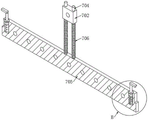
FIG. 4 shows: the utility model is shown in an enlarged schematic view at A in FIG. 3;
FIG. 5 is a diagram: the cross-sectional structure of the scraper of the utility model is schematically shown;
FIG. 6 is a diagram of: the utility model discloses enlarged structure sketch of B department in figure 5.
In the figure: 1. a main body case; 2. a partition plate; 3. a filter screen; 4. a water stop plate; 5. mounting a plate; 6. a stirring assembly; 601. a rotating shaft; 602. a stirring arm; 603. a stirring motor; 604. a hopper; 605. a water outlet pipe; 606. a valve; 7. cleaning the assembly; 701. a screw rod; 702. a moving block; 703. cleaning the motor; 704. a slide bar; 705. a squeegee; 706. a first spring; 707. a fixing plate; 708. a second spring; 709. a slider; 710. a connecting rod; 711. a lifting block; 712. jacking up the rod; 713. a delivery pipe; 8. the door is opened and closed.
Detailed Description
In order to make the objects, technical solutions and advantages of the present application more apparent, the technical solutions of the present application will be described in detail and completely with reference to the following specific embodiments of the present application and the accompanying drawings. It should be apparent that the described embodiments are only some of the embodiments of the present application, and not all of the embodiments. All other embodiments, which can be derived by a person skilled in the art from the embodiments given herein without making any creative effort, shall fall within the protection scope of the present application.
The technical solutions provided by the embodiments of the present application are described in detail below with reference to the accompanying drawings.
Referring to fig. 1-6, the present invention provides a technical solution of an industrial wastewater treatment apparatus:
the utility model provides an industrial wastewater treatment equipment, including main body case 1, and main body case 1 positive left side below position rotates and is connected with opening and shutting door 8, main body case 1's inner wall fixedly connected with baffle 2, one side of baffle 2 and the same filter screen 3 of main body case 1's left side inner wall fixedly connected with, main body case 1's inner wall fixedly connected with sealing plate 4, the opposite side of baffle 2 and the same mounting panel 5 of main body case 1's right side inner wall fixedly connected with, the intercommunication mouth has been seted up to the side of baffle 2, the lower surface of mounting panel 5 is provided with stirring subassembly 6, main body case 1's left side inner wall is provided with clearance subassembly 7.
In this embodiment, as shown in fig. 2, the stirring assembly 6 includes a rotating shaft 601 rotatably connected to the lower surface of the mounting plate 5, the top end of the rotating shaft 601 is rotatably connected to the inner bottom wall of the main body box 1, a stirring arm 602 is fixedly connected to the surface of the rotating shaft 601, a stirring motor 603 is fixedly connected to the upper surface of the mounting plate 5, and the output end of the stirring motor 603 penetrates through the lower surface of the mounting plate 5 and is fixedly connected to the top end of the rotating shaft 601.
The upper surface of the mounting plate 5 is fixedly connected with a hopper 604, the right side of the main body box 1 is fixedly connected with a water outlet pipe 605, and the surface of the water outlet pipe 605 is fixedly connected with a valve 606.
Specifically, the agent is poured into the right side of the partition board 2 in the main box 1 through the hopper 604, the output end of the stirring motor 603 drives the rotating shaft 601 to rotate, and then the stirring arm 602 is driven to rotate, the wastewater and the agent are stirred to accelerate the reaction efficiency, and the treated water is discharged through the matching direction of the water outlet pipe 605 and the valve 606.
In this embodiment, as shown in fig. 3 to 6, the cleaning assembly 7 includes a screw rod 701 rotatably connected to the inner wall of the left side of the main body box 1, the other end of the screw rod 701 is rotatably connected to the left side of the partition board 2, a moving block 702 is connected to the surface of the screw rod 701 in a threaded manner, a cleaning motor 703 is fixedly connected to the right side of the partition board 2, and an output end of the cleaning motor 703 penetrates through the left side of the partition board 2 and is fixedly connected to one end of the screw rod 701.
The upper surface of the moving block 702 is provided with a sliding hole, the inner wall of the sliding hole is slidably connected with a sliding rod 704, the bottom end of the sliding rod 704 is fixedly connected with a scraper 705, the front surface and the back surface of the scraper 705 are respectively slidably connected with the inner walls of the front side and the back side of the main box 1, a first spring 706 is sleeved on the surface of the sliding rod 704, the top end of the first spring 706 is fixedly connected with the lower surface of the moving block 702, the bottom end of the first spring 706 is fixedly connected with the upper surface of the scraper 705, and the side surface of the scraper 705 is provided with a water through hole.
The upper surface of scraper blade 705 is seted up flutedly, and the inner wall fixedly connected with fixed plate 707 of recess, the inner bottom wall fixedly connected with second spring 708 of recess, the top fixedly connected with slider 709 of second spring 708, the surface of slider 709 and the inner wall sliding connection of recess, the upper surface fixedly connected with connecting rod 710 of slider 709, the top of connecting rod 710 runs through the upper surface and the fixedly connected with elevator 711 of fixed plate 707, and connecting rod 710 and fixed plate 707 sliding connection, the chamfer has been seted up on the right side of elevator 711, the equal fixedly connected with jack-up pole 712 of the front and back side inner wall of main part case 1, jack-up pole 712 is the slope setting.
The chip removal port is arranged on the left side of the main body box 1, the conveying pipe 713 is fixedly connected to the position, corresponding to the chip removal port, on the left side of the main body box 1, and the other end of the conveying pipe 713 is fixedly connected with the bottom of the left side of the main body box 1 and penetrates through the inner wall of the main body box 1.
Specifically, the output end of the cleaning motor 703 drives the screw rod 701 to rotate, so as to drive the moving block 702 to move leftward and further drive the sliding rod 704 to move, so as to drive the scraper 705 to move leftward to clean particles on the filter screen 3, the cleaned particles are conveyed into the position below the water stop plate 4 in the main box 1 through the conveying pipe 713 to be temporarily stored, the lower surface of the scraper 705 is tightly attached to the filter screen 3 through the first spring 706, so that the cleaning effect is improved, the lifting block 711 is extruded through the jacking rod 712 when the scraper 705 moves leftward, so as to drive the connecting rod 710 and the slider 709 to compress the second spring 708 and move downward, when the scraper 705 moves rightward, the jacking rod 712 acts on the chamfer on the lifting block 711, so as to lift the lifting block 711 upwards under the cooperation of the slider 709 and the fixing plate 707, so as to drive the scraper 705 to move upwards under the cooperation of the lifting block 707 and the jacking rod 712, until the lifting block 711 is separated from the jacking rod 712, the scraper 705 falls down, so as to prevent part of the particles from moving rightward along the upper surface 705 of the filter screen 3, so that part of the particles cannot be cleaned right side of the scraper can be cleaned, and the temporarily stored particles can be conveniently opened and closed through the centralized processing door 8.
The working principle is as follows: when the industrial wastewater treatment equipment is used, a user firstly pours wastewater into the filter screen 3 in the main box 1, the wastewater flows onto the water stop plate 4 after being filtered, then flows into the right side of the partition plate 2 in the main box 1 through the communication port on the partition plate 2, then pours a medicament into the hopper 604 and turns on the stirring motor 603, the output end of the stirring motor 603 drives the rotating shaft 601 to rotate, the rotating shaft 601 drives the stirring arm 602 to rotate, the wastewater and the medicament are stirred to accelerate the reaction efficiency, after the reaction is completed, the valve 606 is opened, and the treated water is discharged by using the water outlet pipe 605; when particle impurities of the filter screen 3 need to be cleaned, the cleaning motor 703 is started, the output end of the cleaning motor 703 drives the screw rod 701 to rotate, the screw rod 701 drives the moving block 702 to move leftwards, the moving block 702 drives the sliding rod 704 to move, the sliding rod 704 drives the scraper 705 to move leftwards to clean particles on the filter screen 3, the cleaned particles are conveyed into the position below the water stop plate 4 in the main box 1 through the conveying pipe 713 to be temporarily stored, finally the opening and closing door 8 is opened to intensively treat the temporarily stored particles, in the process, the lower surface of the scraper 705 is tightly attached to the filter screen 3 through the first spring 706, the cleaning effect is improved, when the scraper 705 moves leftwards, the lifting rod 712 extrudes the lifting block 711 under the matching of the sliding block 709 and the fixing plate 707 to drive the connecting rod 710 and the sliding block 709 to compress the second spring 708 and move downwards, when the scraper 705 moves rightwards, the lifting rod 712 acts on a chamfer on the lifting block 711, the lifting block 705 is lifted upwards, the problem that the scraper 705 can prevent the scraper from moving upwards along the surface 705 of the lifting block 707 under the condition that the cleaning of the filter screen can not be easily cleaned, and the problem that the existing industrial waste water treatment equipment cannot be easily cleaned can be easily solved.
It should also be noted that the terms "comprises," "comprising," or any other variation thereof, are intended to cover a non-exclusive inclusion, such that a process, method, article, or apparatus that comprises a list of elements does not include only those elements but may include other elements not expressly listed or inherent to such process, method, article, or apparatus. Without further limitation, an element defined by the phrase "comprising a … …" does not exclude the presence of another identical element in a process, method, article, or apparatus that comprises the element.
The above description is only an example of the present application and is not intended to limit the present application. Various modifications and changes may occur to those skilled in the art to which the present application pertains. Any modification, equivalent replacement, improvement, etc. made within the spirit and principle of the present application should be included in the scope of the claims of the present application.
Claims (7)
1. The utility model provides an industrial wastewater treatment equipment, includes main body case (1), and main body case (1) positive left side below position rotation is connected with door (8) that open and shut, its characterized in that: the inner wall fixedly connected with baffle (2) of main part case (1), one side of baffle (2) and the same filter screen of left side inner wall fixedly connected with (3) of main part case (1), the inner wall fixedly connected with sealing plate (4) of main part case (1), the opposite side of baffle (2) and the same mounting panel of right side inner wall fixedly connected with (5) of main part case (1), the intercommunication mouth has been seted up to the side of baffle (2), the lower surface of mounting panel (5) is provided with stirring subassembly (6), the left side inner wall of main part case (1) is provided with clearance subassembly (7).
2. The industrial wastewater treatment plant according to claim 1, characterized in that: stirring subassembly (6) include axis of rotation (601) of being connected with the lower surface rotation of mounting panel (5), and the top of axis of rotation (601) rotates with the interior diapire of main part case (1) and is connected, the fixed surface of axis of rotation (601) is connected with stirring arm (602), the last fixed surface of mounting panel (5) is connected with agitator motor (603), the output of agitator motor (603) run through the lower surface of mounting panel (5) and with the top fixed connection of axis of rotation (601).
3. The industrial wastewater treatment plant according to claim 1, characterized in that: the upper surface fixed connection of mounting panel (5) has hopper (604), the right side fixed connection of main part case (1) has outlet pipe (605), the fixed surface of outlet pipe (605) is connected with valve (606).
4. The industrial wastewater treatment plant according to claim 1, characterized in that: the cleaning assembly (7) comprises a screw rod (701) rotatably connected with the inner wall of the left side of the main body box (1), the other end of the screw rod (701) is rotatably connected with the left side of the partition plate (2), a moving block (702) is in threaded connection with the surface of the screw rod (701), a cleaning motor (703) is fixedly connected to the right side of the partition plate (2), and the output end of the cleaning motor (703) penetrates through the left side of the partition plate (2) and is fixedly connected with one end of the screw rod (701).
5. The industrial wastewater treatment plant according to claim 4, characterized in that: the upper surface of the moving block (702) is provided with a sliding hole, the inner wall of the sliding hole is connected with a sliding rod (704) in a sliding mode, the bottom end of the sliding rod (704) is fixedly connected with a scraper (705), the front side and the back side of the scraper (705) are respectively connected with the inner walls of the front side and the back side of the main box (1) in a sliding mode, a first spring (706) is sleeved on the surface of the sliding rod (704), the top end of the first spring (706) is fixedly connected with the lower surface of the moving block (702), the bottom end of the first spring (706) is fixedly connected with the upper surface of the scraper (705), and the side face of the scraper (705) is provided with a water through hole.
6. The industrial wastewater treatment plant according to claim 5, characterized in that: the upper surface of scraper blade (705) is seted up flutedly, and the inner wall fixedly connected with fixed plate (707) of recess, inner bottom wall fixedly connected with second spring (708) of recess, top fixedly connected with slider (709) of second spring (708), the surface of slider (709) and the inner wall sliding connection of recess, the upper surface fixedly connected with connecting rod (710) of slider (709), the top of connecting rod (710) runs through upper surface and fixedly connected with elevator (711) of fixed plate (707), and connecting rod (710) and fixed plate (707) sliding connection, the chamfer has been seted up on the right side of elevator (711), equal fixedly connected with jack-up pole (712) of the front and back side inner wall of main part case (1), jack-up pole (712) are the slope setting.
7. The industrial wastewater treatment plant according to claim 1, characterized in that: the chip removal port is formed in the left side of the main body box (1), the conveying pipe (713) is fixedly connected to the left side of the main body box (1) and corresponds to the chip removal port, and the other end of the conveying pipe (713) is fixedly connected with the left bottom of the main body box (1) and penetrates through the inner wall of the main body box (1).
Priority Applications (1)
| Application Number | Priority Date | Filing Date | Title |
|---|---|---|---|
| CN202220859266.1U CN218046694U (en) | 2022-04-14 | 2022-04-14 | Industrial wastewater treatment equipment |
Applications Claiming Priority (1)
| Application Number | Priority Date | Filing Date | Title |
|---|---|---|---|
| CN202220859266.1U CN218046694U (en) | 2022-04-14 | 2022-04-14 | Industrial wastewater treatment equipment |
Publications (1)
| Publication Number | Publication Date |
|---|---|
| CN218046694U true CN218046694U (en) | 2022-12-16 |
Family
ID=84416092
Family Applications (1)
| Application Number | Title | Priority Date | Filing Date |
|---|---|---|---|
| CN202220859266.1U Active CN218046694U (en) | 2022-04-14 | 2022-04-14 | Industrial wastewater treatment equipment |
Country Status (1)
| Country | Link |
|---|---|
| CN (1) | CN218046694U (en) |
-
2022
- 2022-04-14 CN CN202220859266.1U patent/CN218046694U/en active Active
Similar Documents
| Publication | Publication Date | Title |
|---|---|---|
| CN112108491A (en) | Environment-friendly refuse handling installation | |
| CN209985877U (en) | Energy-conserving belt cleaning device of garrulous glass | |
| CN111573909A (en) | Processing apparatus that filters coal washing waste water and can retrieve coal on residue | |
| CN214496031U (en) | Iron-containing wastewater treatment device based on variable-current electromagnetic iron removal | |
| CN214551490U (en) | Waste water treatment device for commercial concrete mixer | |
| CN218046694U (en) | Industrial wastewater treatment equipment | |
| CN109276948A (en) | Device for filtering impurities in a kind of industrial wastewater | |
| CN218797754U (en) | Rice cleaning mechanism is used in rice flour processing | |
| CN215975336U (en) | Multistage filter equipment for sewage treatment | |
| CN215387950U (en) | Filter equipment is used in cleaner production | |
| CN210631746U (en) | Environment-friendly building sewage treatment device | |
| CN211521867U (en) | Environmental protection equipment with sewage treatment mechanism | |
| CN220572896U (en) | A multistage filtration for sewage treatment | |
| CN214982433U (en) | Toy is raw materials processingequipment for intelligent manufacturing | |
| CN220766563U (en) | Sewage filtering equipment with adjustable filtering grade | |
| CN212467400U (en) | Sewage precipitation circulating device | |
| CN220635586U (en) | Raw material cleaning device for food engineering | |
| CN211274233U (en) | Chemical product ceramic membrane filter | |
| CN219771919U (en) | Sewage treatment device with impurity removing mechanism | |
| CN216997978U (en) | Green building sewage treatment plant | |
| CN216639228U (en) | Municipal sludge treatment device with graded filtering function | |
| CN213141669U (en) | Novel wastewater treatment device | |
| CN219984110U (en) | Water rotary type filtering device for coating equipment | |
| CN217188131U (en) | Prevent sewage treatment plant of jam | |
| CN214829097U (en) | Automatic abluent industrial waste water treatment reaction tank |
Legal Events
| Date | Code | Title | Description |
|---|---|---|---|
| GR01 | Patent grant | ||
| GR01 | Patent grant |