CN218031663U - Water tap with plugging structure - Google Patents
Water tap with plugging structure Download PDFInfo
- Publication number
- CN218031663U CN218031663U CN202222184434.4U CN202222184434U CN218031663U CN 218031663 U CN218031663 U CN 218031663U CN 202222184434 U CN202222184434 U CN 202222184434U CN 218031663 U CN218031663 U CN 218031663U
- Authority
- CN
- China
- Prior art keywords
- faucet
- hole
- water
- tap
- shell
- Prior art date
- Legal status (The legal status is an assumption and is not a legal conclusion. Google has not performed a legal analysis and makes no representation as to the accuracy of the status listed.)
- Active
Links
- XLYOFNOQVPJJNP-UHFFFAOYSA-N water Substances O XLYOFNOQVPJJNP-UHFFFAOYSA-N 0.000 title claims abstract description 40
- 238000007789 sealing Methods 0.000 claims abstract description 40
- 230000000903 blocking effect Effects 0.000 claims description 5
- 239000004033 plastic Substances 0.000 claims description 4
- 229920003023 plastic Polymers 0.000 claims description 4
- 238000001746 injection moulding Methods 0.000 claims description 3
- 230000000149 penetrating effect Effects 0.000 claims 1
- 230000000694 effects Effects 0.000 abstract description 12
- 239000011148 porous material Substances 0.000 abstract description 3
- 238000005406 washing Methods 0.000 description 3
- 230000004048 modification Effects 0.000 description 2
- 238000012986 modification Methods 0.000 description 2
- 239000000243 solution Substances 0.000 description 2
- 230000009286 beneficial effect Effects 0.000 description 1
- 230000003139 buffering effect Effects 0.000 description 1
- 238000006073 displacement reaction Methods 0.000 description 1
- 238000010030 laminating Methods 0.000 description 1
- 239000000463 material Substances 0.000 description 1
- 231100000252 nontoxic Toxicity 0.000 description 1
- 230000003000 nontoxic effect Effects 0.000 description 1
- 238000002791 soaking Methods 0.000 description 1
- 239000000126 substance Substances 0.000 description 1
- 230000009967 tasteless effect Effects 0.000 description 1
Images

Landscapes
- Lift Valve (AREA)
Abstract
The utility model provides a tap with block structure, including tap shell, tap shell includes tap mouth and is used for there being the linkage segment in water piping connection, tap shell's top and inside all offer the apical pore and the water sealing hole that are used for installing the case, the guide block is installed to the inner wall of linkage segment, the through hole has been seted up at the middle part of guide block, the shutoff subassembly is installed to interlude in the through hole, shutoff subassembly through the setting, when tap shell breaks off in linkage segment department, because make the sealing washer drive the ejector pin remove to the sealing washer is located the seal groove in the through hole under hydraulic effect, end department through the sealing washer to the linkage segment seals, thereby the shutoff effect has been played, avoid tap shell to break off and lead to user's house bubble water, user's economic loss has effectively been reduced.
Description
Technical Field
The utility model belongs to the technical field of tap, concretely relates to tap with block structure.
Background
The faucet is a popular name of a water valve, a size switch used for controlling water flow has the effect of saving water, the faucet is widely used in daily life, along with the wide use of a full-automatic washing machine, a quick-opening small faucet for the washing machine also has wide market prospects, however, the market quality of the quick-opening small faucet for the washing machine on the market is uneven, when the faucet is broken, a user can bubble water in a house, and great economic loss is caused to the user, so that the faucet capable of playing a role in blocking when the faucet is broken is necessary, through search and discovery, the application number of 202020760666.8 discloses a reinforced sealing and leakage-proof household faucet, wherein the situation that 'the valve hole sealing ring cannot lose elasticity or deformation by utilizing the buffering effect of a spring, the valve hole can be squeezed and sealed without water dripping and leaking' is recorded, but the connection section generally exists in the water pipe when the faucet is broken, and the connection section can be remained in the water pipe, so that the valve body arranged in the water faucet valve hole cannot play a role in blocking effect.
SUMMERY OF THE UTILITY MODEL
An object of the utility model is to provide a tap with block structure aims at solving the problem that proposes in the background art.
In order to achieve the above object, the utility model provides a following technical scheme: a faucet with a plugging structure comprises a faucet shell, wherein the faucet shell comprises a faucet mouth and a connecting section for connecting a water pipe, the top end and the inside of the faucet shell are both provided with a top hole for installing a valve core and a water sealing hole, the inner wall of the connecting section is provided with a guide block, the middle part of the guide block is provided with a through hole, and a plugging component is inserted and installed in the through hole;
the plugging assembly comprises an ejector rod and a sealing ring, the sealing ring is installed at one end of the ejector rod, and the ejector rod is installed in the through hole in an inserting mode.
As an optimal technical scheme of the utility model, the sealing washer is O shape rubber circle, tap shell adopts the integrative injection moulding of PP plastics.
As an optimal technical scheme, the seal groove has been seted up to the port department of linkage segment, seal groove and sealing washer size phase-match.
As a preferred technical scheme of the utility model, the ejector pin is long 49mm and the inner wall that is located water sealing hole one side in the one end laminating tap shell.
As a preferred technical scheme of the utility model, the distance is 8mm between the end department of sealing washer and linkage segment.
Compared with the prior art, the beneficial effects of the utility model are that: through the shutoff subassembly that sets up, when tap shell broke off in linkage segment department, because make the sealing washer drive the ejector pin and move in the through hole to the sealing washer and be located the seal groove under hydraulic effect, sealed the end department of linkage segment through the sealing washer to played the shutoff effect, avoided tap shell fracture to lead to user's house to steep water, effectively reduced user's economic loss.
Drawings
The accompanying drawings are included to provide a further understanding of the invention, and are incorporated in and constitute a part of this specification, illustrate embodiments of the invention, and together with the description serve to explain the invention and not to limit the invention. In the drawings:
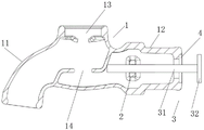
fig. 1 is a schematic structural view of the present invention;
fig. 2 is a schematic sectional view of the present invention.
In the figure: 1. a faucet housing; 11. a faucet mouth; 12. a connection section; 13. a top hole; 14. sealing the water hole; 2. a guide block; 3. a plugging component; 31. a top rod; 32. a seal ring; 4. sealing the groove.
Detailed Description
The technical solutions in the embodiments of the present invention will be described clearly and completely with reference to the accompanying drawings in the embodiments of the present invention, and it is obvious that the described embodiments are only some embodiments of the present invention, not all embodiments. Based on the embodiments in the present invention, all other embodiments obtained by a person skilled in the art without creative work belong to the protection scope of the present invention.
Referring to fig. 1-2, the present invention provides the following technical solutions: the utility model provides a tap with block structure, includes tap shell 1, tap shell 1 includes tap mouth 11 and is used for there being linkage segment 12 in water piping connection, and tap shell 1's top and inside all offer the apical pore 13 that is used for installing the case and seal water hole 14, and guide block 2 is installed to the inner wall of linkage segment 12, and the through hole has been seted up at the middle part of guide block 2, and shutoff subassembly 3 has been installed to the interlude in the through hole.
Preferably, the plugging assembly 3 comprises a top rod 31 and a sealing ring 32, wherein the sealing ring 32 is installed at one end of the top rod 31, and the top rod 31 is inserted into the through hole.
Specifically, when water tap shell 1 broke off in linkage segment 12 department, because make sealing washer 32 drive ejector pin 31 and remove in the through hole under the hydraulic effect, sealed the end department of linkage segment 12 through sealing washer 32 to play the shutoff effect, avoided water tap shell 1 to break off and lead to user's house to steep water.
Preferably, sealing washer 32 is O shape rubber circle, and tap housing 1 adopts the integrative injection moulding of PP plastics, and seal groove 4 has been seted up to the port department of linkage segment 12, and seal groove 4 and sealing washer 32 size phase-match, PP level plastics are nontoxic harmless tasteless as accessory raw and other materials, can not produce harmful substance in daily use and long-time soaking aquatic.
Specifically, the through hole through setting up in 2 middle parts of guide block has played the removal guide effect to ejector pin 31, when sealing washer 32 removed to seal groove 4 department under hydraulic effect, utilized the cooperation of O shape rubber circle and seal groove 4 to play sealed shutoff effect to the end department of linkage segment 12, has effectively promoted the shutoff effect of linkage segment 12.
Preferably, the ejector rod 31 is 49mm long, one end of the ejector rod is attached to the inner wall of the water sealing hole 14 side in the water faucet shell 1, and the distance between the sealing ring 32 and the end of the connecting section 12 is 8mm.
Specifically, when the water faucet is used normally, because one end of the ejector rod 31 is attached to the inner wall of the water sealing hole 14 side in the water faucet shell 1 and the distance between the end of the sealing ring 32 and the connecting section 12 is 8mm, the sealing ring 32 does not influence the water yield when the water faucet shell 1 is used normally.
The working principle is as follows: install the case in apical pore 13 and water hole 14 department of sealing, utilize the switching and the water yield of this tap of case control, install linkage segment 12 in the water pipe, when tap shell 1 breaks off in linkage segment 12 department, consequently, the inner wall that lies in water hole 14 one side in tap shell 1 can't play limiting displacement to ejector pin 31, make sealing washer 32 drive ejector pin 31 remove in the through hole under hydraulic effect, thereby make sealing washer 32 remove to seal groove 4 department and carry out the shutoff to the end department of linkage segment 12, and then water pipe water-logging blowout causes user's house to soak when avoiding tap shell 1 to break, the effectual economic loss who reduces the user.
Finally, it should be noted that: although the present invention has been described in detail with reference to the foregoing embodiments, it will be apparent to those skilled in the art that modifications may be made to the embodiments described in the foregoing embodiments, or equivalents may be substituted for elements thereof. Any modification, equivalent replacement, or improvement made within the spirit and principle of the present invention should be included in the protection scope of the present invention.
Claims (5)
1. A faucet with a blocking structure, comprising a faucet housing (1), characterized in that: the faucet comprises a faucet shell (1) and a water pipe, wherein the faucet shell (1) comprises a faucet mouth (11) and a connecting section (12) used for connecting a water pipe, a top hole (13) used for installing a valve core and a water sealing hole (14) are formed in the top end and the inside of the faucet shell (1), a guide block (2) is installed on the inner wall of the connecting section (12), a through hole is formed in the middle of the guide block (2), and a plugging component (3) is installed in the through hole in an inserting mode;
the plugging assembly (3) comprises an ejector rod (31) and a sealing ring (32), wherein the sealing ring (32) is installed at one end of the ejector rod (31), and the ejector rod (31) is installed in the through hole in a penetrating mode.
2. The faucet with the blocking structure as recited in claim 1, wherein: the sealing ring (32) is an O-shaped rubber ring, and the faucet shell (1) is integrally formed by injection molding of PP plastics.
3. The faucet with the blocking structure as recited in claim 1, wherein: seal groove (4) have been seted up to the port department of linkage segment (12), seal groove (4) and sealing washer (32) size phase-match.
4. A faucet having a closure structure according to claim 1, wherein: the ejector rod (31) is 49mm long, and one end of the ejector rod is attached to the inner wall of the water sealing hole (14) side in the water faucet shell (1).
5. A faucet having a closure structure according to claim 1, wherein: the distance between the sealing ring (32) and the end of the connecting section (12) is 8mm.
Priority Applications (1)
| Application Number | Priority Date | Filing Date | Title |
|---|---|---|---|
| CN202222184434.4U CN218031663U (en) | 2022-08-19 | 2022-08-19 | Water tap with plugging structure |
Applications Claiming Priority (1)
| Application Number | Priority Date | Filing Date | Title |
|---|---|---|---|
| CN202222184434.4U CN218031663U (en) | 2022-08-19 | 2022-08-19 | Water tap with plugging structure |
Publications (1)
| Publication Number | Publication Date |
|---|---|
| CN218031663U true CN218031663U (en) | 2022-12-13 |
Family
ID=84348568
Family Applications (1)
| Application Number | Title | Priority Date | Filing Date |
|---|---|---|---|
| CN202222184434.4U Active CN218031663U (en) | 2022-08-19 | 2022-08-19 | Water tap with plugging structure |
Country Status (1)
| Country | Link |
|---|---|
| CN (1) | CN218031663U (en) |
-
2022
- 2022-08-19 CN CN202222184434.4U patent/CN218031663U/en active Active
Similar Documents
| Publication | Publication Date | Title |
|---|---|---|
| CN113847653A (en) | Humidifying device and air conditioner | |
| CN113216897A (en) | Float collar float shoe for well cementation construction | |
| CN2139960Y (en) | Flush toilet sewer valve | |
| CN216173310U (en) | Water outlet device capable of stopping immediately after being closed | |
| CN221097509U (en) | Leak-proof plastic valve | |
| CN209808271U (en) | A hard water softening device capable of controlling water volume | |
| CN210265927U (en) | Water stop pad of needle valve water inlet valve | |
| CN211082429U (en) | Two-position three-way reversing valve with self-locking gas circuit | |
| CN205226514U (en) | Water tap | |
| CN220980420U (en) | Leak-proof sealing valve | |
| CN201228808Y (en) | Ball-cock | |
| CN219774884U (en) | Sealing element applied to three-way ball valve | |
| CN222912095U (en) | Multifunctional drain plug and refrigerator thereof | |
| CN223137050U (en) | A slow closing check valve to prevent water hammer | |
| CN218207037U (en) | Anti-puncture fixed valve assembly | |
| CN217153895U (en) | Adopt waterproof flower art lamp of ultrasonic wave plastic part | |
| CN221982579U (en) | A cutting ring for a concrete pump | |
| CN217029968U (en) | Environment-friendly material-saving PP integrated valve | |
| CN219975356U (en) | High-flow high-sealing stop valve | |
| CN214466178U (en) | Stainless steel stop valve | |
| CN218377820U (en) | A stable pressure-holding valve | |
| CN220667895U (en) | Internal oil duct sealing structure for split pump | |
| CN217951282U (en) | Liquid valve convenient to change case | |
| CN214579164U (en) | Flow control drain valve body | |
| CN216843203U (en) | Novel straight-through ball valve |
Legal Events
| Date | Code | Title | Description |
|---|---|---|---|
| GR01 | Patent grant | ||
| GR01 | Patent grant |