CN218020004U - Cable head protective sheath former - Google Patents
Cable head protective sheath former Download PDFInfo
- Publication number
- CN218020004U CN218020004U CN202220829525.6U CN202220829525U CN218020004U CN 218020004 U CN218020004 U CN 218020004U CN 202220829525 U CN202220829525 U CN 202220829525U CN 218020004 U CN218020004 U CN 218020004U
- Authority
- CN
- China
- Prior art keywords
- switching
- cable head
- mold
- head protective
- fixed
- Prior art date
- Legal status (The legal status is an assumption and is not a legal conclusion. Google has not performed a legal analysis and makes no representation as to the accuracy of the status listed.)
- Active
Links
Images


Landscapes
- Extrusion Moulding Of Plastics Or The Like (AREA)
Abstract
The utility model provides a cable head protective sleeve forming device, which comprises an extruder, a discharging component and an adjusting mechanism, wherein the discharging component is connected with the tail end of the extruder; adjustment mechanism includes chassis, switching subassembly, two moulds and two shaping subassemblies, the switching subassembly with the shaping subassembly all is located on the chassis, two the mould all with the switching subassembly is connected, the shaping subassembly is located the mould top, the mould with the shaping subassembly one-to-one, this cable head protective sheath former, structural design is reasonable, through switching subassembly, two moulds and two shaping subassembly cooperations, can realize the duplex position extrusion molding, neither influences product extrusion molding production speed, can reserve time again for the product is at the mould internal cooling design back drawing of patterns, prevents that the product from receiving the compressive deformation.
Description
Technical Field
The utility model relates to a cable head protective sheath production field especially relates to a cable head protective sheath former.
Background
The cable head protective sleeve is formed by compounding a cross-linked polyolefin material and a hot melt adhesive, the cable head protective sleeve is sleeved at the branch of the core of the multi-core cable and is heated to shrink, the hot melt adhesive on the inner wall can tightly adhere to the cable, the waterproof and moistureproof sealing protection effect is achieved, and the outer radiation cross-linked polyolefin material can achieve the electrical insulation protection effect.
The semi-manufactured goods of cable head protective sheath need the storage of multiple raw materials compounding crosslinked, the direct drawing of patterns of extrusion molding, but the product temperature after the extrusion molding is still higher, and the product is softer, and the storage of direct drawing of patterns causes the product compression to warp easily, and current solution is: the extruded product still needs to be cooled in the die for a period of time, so that the temperature of the product is reduced to avoid compression deformation, but the increase of the cooling time reduces the extrusion production speed of the product.
Therefore, a cable head protective sleeve forming device is provided to solve the problems.
SUMMERY OF THE UTILITY MODEL
In view of the above shortcomings of the prior art, an object of the present invention is to provide a cable head protective sheath forming apparatus for solving the problem of the decrease of the production efficiency of the protective sheath caused by the increase of cooling time of the conventional cable head protective sheath forming apparatus for preventing the product from deforming under pressure.
In order to achieve the above and other related purposes, the utility model provides a cable head protective sleeve forming device, which comprises an extruder, a discharging component and an adjusting mechanism, wherein the discharging component is connected to the tail end of the extruder; the adjusting mechanism comprises an underframe, a switching assembly, two dies and two forming assemblies, wherein the switching assembly and the forming assemblies are located on the underframe, the dies are connected with the switching assembly, the forming assemblies are located above the dies, and the dies correspond to the forming assemblies one to one.
In an embodiment of the utility model, the ejection of compact subassembly includes the ejection of compact stub bar with the extruder intercommunication, ejection of compact stub bar bottom is equipped with screw thread portion, the ejection of compact stub bar has the regulation head through screw thread portion screw-thread fit, adjust the head with ejection of compact head intercommunication.
In an embodiment of the present invention, a collecting groove is disposed below the bottom frame.
In an embodiment of the utility model, the mould includes fixed mould and removal mould, the fixed mould towards remove one side of mould with remove the mould and all be equipped with towards one side of fixed mould and hold the chamber, two it forms into the die cavity to hold the chamber cooperation, the fixed mould below is fixed with the support, be equipped with the guide rail on the support, it slides along the guide rail to remove the mould, the support is kept away from one side of fixed mould is fixed with the removal cylinder, the piston rod of removal cylinder with remove the mould and connect.
In an embodiment of the present invention, the switching assembly includes a switching cylinder and a horizontal guide rod fixed to the bottom frame, the bracket slides along the horizontal guide rod, and the switching cylinder drives the bracket to move.
In an embodiment of the present invention, the fixed mold and the movable mold are both provided with a cooling assembly, the cooling assembly includes a cooling cavity, a liquid inlet pipe and a liquid discharge pipe, the cooling cavity is located in the fixed mold and the movable mold, and the cooling cavity is communicated with the liquid inlet pipe and the liquid discharge pipe.
In an embodiment of the utility model, the shaping subassembly includes vertical locating support frame on the chassis, the support frame top is equipped with the lift cylinder, lift cylinder piston rod bottom is connected with the switching piece, switching piece below is connected with the insert tube, the switching piece be equipped with the trachea of insert tube intercommunication.
As described above, the utility model discloses following beneficial effect has:
the utility model has the advantages of reasonable design, through switching over subassembly, two moulds and two shaping subassembly cooperations, can realize the duplex position extrusion molding, neither influence product extrusion molding production speed, can reserve time again for the product is in the mould internal cooling design back drawing of patterns, prevents that the product pressurized from warping.
Drawings
Fig. 1 shows the embodiment of the present invention discloses a schematic structural diagram of a cable head protective sheath forming apparatus.
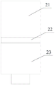
Fig. 2 shows as the embodiment of the present invention discloses a structure diagram of a discharging component of a cable head protective sheath forming device.
Fig. 3 shows as the embodiment of the present invention discloses a structure diagram of a mold of a cable head protective sheath forming apparatus.
Fig. 4 shows the embodiment of the present invention discloses a schematic structural diagram of a forming assembly of a cable head protective sheath forming apparatus.
Description of the element reference numerals
1. An extruder; 2. a discharge assembly; 21. discharging a stub bar; 22. a threaded portion; 23. an adjustment head; 3. a chassis; 4. a horizontal guide rod; 5. a mold; 51. a support; 52. a guide rail; 53. a moving cylinder; 54. moving the mold; 55. An accommodating chamber; 56. a fixed mold; 6. a molding assembly; 61. a support frame; 62. a lifting cylinder; 63. a transfer block; 64. an insertion tube; 65. an air tube; 7. and switching the cylinders.
Detailed Description
The following description is provided for illustrative purposes, and other advantages and features of the present invention will become apparent to those skilled in the art from the following detailed description.
Please refer to fig. 1 to 4. It should be understood that the structure, proportion, size and the like shown in the drawings attached to the present specification are only used for matching with the content disclosed in the specification, so as to be known and read by those skilled in the art, and are not used for limiting the limit conditions of the present invention, so that the present invention does not have the substantial technical significance, and the modification of any structure, the change of the proportion relation or the adjustment of the size should still fall within the scope of the technical content disclosed in the present invention without affecting the function and the achievable purpose of the present invention. In addition, the terms such as "upper", "lower", "left", "right", "middle" and "one" used in the present specification are used for clarity of description only, and are not used to limit the scope of the present invention, and the relative relationship between the terms may be changed or adjusted without substantial technical changes.
Referring to fig. 1-4, the present invention provides the preferred embodiment:
a cable head protective sleeve forming device comprises an extruder 1, a discharging assembly 2 and an adjusting mechanism, wherein the discharging assembly 2 is connected to the tail end of the extruder 1; adjustment mechanism includes chassis 3, switching subassembly, two moulds 5 and two shaping subassemblies 6, and switching subassembly and shaping subassembly 6 all are located chassis 3, and two moulds 5 all are connected with the switching subassembly, and shaping subassembly 6 is located mould 5 top, and mould 5 and shaping subassembly 6 one-to-one.
The discharging component 2 comprises a discharging head 21 communicated with the extruder 1, the bottom of the discharging head 21 is provided with a threaded part 22, an adjusting head 23 is in threaded fit with the discharging head 21 through the threaded part 22, and the adjusting head 23 is communicated with the discharging head 21; adjusting head 23 below is equipped with cutting assembly, and cutting assembly includes cutting cylinder and blade, and cutting cylinder drive blade removes and cuts off the material that extruder 1 extruded.
A collecting tank is arranged below the underframe 3; the collecting tank is used for receiving the products falling after demolding, and workers can conveniently finish and carry the products to the next procedure.
The mold 5 comprises a fixed mold 56 and a movable mold 54, wherein both one side of the fixed mold 56 facing the movable mold 54 and one side of the movable mold 54 facing the fixed mold 56 are provided with accommodating cavities 55, the two accommodating cavities 55 are matched to form a forming cavity, a support 51 is fixed below the fixed mold 56, a guide rail 52 is arranged on the support 51, the movable mold 54 slides along the guide rail 52, a movable air cylinder 53 is fixed on one side of the support 51 far away from the fixed mold 56, and a piston rod of the movable air cylinder 53 is connected with the movable mold 54; when forming, the moving cylinder 53 drives the moving die 54 to move along the guide rail 52 until the moving die is in butt fit with the fixed die 56, the two containing cavities 55 form forming cavities for receiving materials cut by the cutting assembly, and when demoulding, the moving cylinder 53 drives the moving die 54 to move along the guide rail 52, so that the moving die 54 is separated from the fixed die 56, and the product is released and dropped.
The switching assembly comprises a switching cylinder and a horizontal guide rod 4, the switching cylinder is fixed on the bottom frame 3, the bracket 51 slides along the horizontal guide rod 4, and the switching cylinder drives the bracket 51 to move; switching module drive left side mould 5 moves to the right side and receives the material to ejection of compact subassembly 2 below, switching module moves left side mould 5 to the left side 6 below of forming assembly and makes the material shaping be the product after cooling, and the drawing of patterns after cooling the product, switching module drive right side mould 5 moves to the left side simultaneously and receives the material to ejection of compact subassembly 2 below, then switching module drive left side mould 5 moves to the right side, drive right side mould 5 moves to the right side, left side mould 5 receives the material this moment, 5 forming product of right side mould is to the drawing of patterns after cooling the product, repeat above-mentioned step.
The fixed die 56 and the movable die 54 are both provided with cooling assemblies, each cooling assembly comprises a cooling cavity, a liquid inlet pipe and a liquid outlet pipe, the cooling cavities are positioned in the fixed die 56 and the movable die 54, and the cooling cavities are communicated with the liquid inlet pipes and the liquid outlet pipes; the low-temperature cooling liquid enters the cooling cavity from the liquid inlet pipe, and is discharged from the liquid discharge pipe after absorbing the heat of the mold 5 and the product, so that the product is rapidly cooled and shaped.
The forming assembly 6 comprises a supporting frame 61 vertically arranged on the underframe 3, a lifting cylinder 62 is arranged above the supporting frame 61, the bottom end of a piston rod of the lifting cylinder 62 is connected with a switching block 63, an inserting pipe 64 is connected below the switching block 63, and an air pipe 65 communicated with the inserting pipe 64 is arranged on the switching block 63; when forming, the lifting cylinder 62 drives the transfer block 63 and the insertion tube 64 to move downwards, so that the insertion tube 64 is inserted into the mold 5, the air tube 65 is aerated to form a product, and when demolding, the lifting cylinder 62 drives the transfer block 63 and the insertion tube 64 to move upwards.
In the utility model, the extruder 1 carries out blending, heating, crosslinking and extrusion on the raw materials, and the strip-shaped materials flow out from the discharging component 2; firstly, the switching component works, the left side die 5 is driven to move rightwards to the lower part of the discharging component 2 to receive materials, the right side die 5 is not moved at the moment, then the left side die 5 is moved leftwards to the lower part of the left side forming component 6 by the switching component, the left side forming module works to enable the materials to be formed into products, the cooling component works to cool the products, the moving die 54 is separated from the fixed die 56 to enable the products to be demoulded, meanwhile, the right side die 5 is driven to move leftwards to the lower part of the discharging component 2 to receive the materials by the switching component, then the left side die 5 is driven to move rightwards by the switching component, the right side die 5 is driven to move rightwards, the left side die 5 receives the materials at the moment, the right side die 5 forms the products and demoulds the products after cooling, and the steps are repeated to complete the quick extrusion molding production of the products and the quick cooling and demoulding of the products.
To sum up, the utility model has the advantages of reasonable design, through switching over subassembly, two moulds 5 and 6 cooperations of two shaping subassemblies, can realize the duplex position extrusion molding, neither influence product extrusion molding production speed, can reserve time again for the product is at the 5 internal cooling of mould design back drawing of patterns, prevents that the product pressurized from warping.
The above embodiments are merely illustrative of the principles and effects of the present invention, and are not to be construed as limiting the invention. Modifications and variations can be made to the above-described embodiments by those skilled in the art without departing from the spirit and scope of the present invention. Accordingly, it is intended that all equivalent modifications or changes which may be made by those skilled in the art without departing from the spirit and technical spirit of the present invention shall be covered by the claims of the present invention.
Claims (7)
1. The cable head protective sleeve forming equipment is characterized by comprising an extruder, a discharging assembly and an adjusting mechanism, wherein the discharging assembly is connected to the tail end of the extruder;
the adjusting mechanism comprises an underframe, a switching assembly, two dies and two forming assemblies, wherein the switching assembly and the forming assemblies are located on the underframe, the dies are connected with the switching assembly, the forming assemblies are located above the dies, and the dies correspond to the forming assemblies one to one.
2. The cable head protective sleeve forming device according to claim 1, wherein the discharging assembly comprises a discharging head communicated with the extruder, a threaded portion is arranged at the bottom of the discharging head, the discharging head is in threaded fit with an adjusting head through the threaded portion, and the adjusting head is communicated with the discharging head.
3. The cable head protective sleeve forming device according to claim 1, wherein a collecting groove is arranged below the underframe.
4. The cable head protective sleeve forming device according to claim 1, wherein the mold comprises a fixed mold and a movable mold, a side of the fixed mold facing the movable mold and a side of the movable mold facing the fixed mold are both provided with accommodating cavities, the two accommodating cavities cooperate to form a forming cavity, a support is fixed below the fixed mold, the support is provided with a guide rail, the movable mold slides along the guide rail, a side of the support away from the fixed mold is fixed with a movable cylinder, and a piston rod of the movable cylinder is connected with the movable mold.
5. The cable head protective sheath forming device of claim 4, wherein the switching assembly comprises a switching cylinder and a horizontal guide rod fixed on the bottom frame, the bracket slides along the horizontal guide rod, and the switching cylinder drives the bracket to move.
6. The cable head protective sleeve forming device according to claim 4, wherein the fixed mold and the movable mold are each provided with a cooling assembly, the cooling assembly comprises a cooling cavity, a liquid inlet pipe and a liquid outlet pipe, the cooling cavity is located in the fixed mold and the movable mold, and the cooling cavity is communicated with the liquid inlet pipe and the liquid outlet pipe.
7. The cable head protective sleeve forming device according to claim 1, wherein the forming assembly comprises a support vertically arranged on the bottom frame, a lifting cylinder is arranged above the support, a transfer block is connected to the bottom end of a piston rod of the lifting cylinder, an insertion tube is connected to the lower side of the transfer block, and an air tube communicated with the insertion tube is arranged on the transfer block.
Priority Applications (1)
| Application Number | Priority Date | Filing Date | Title |
|---|---|---|---|
| CN202220829525.6U CN218020004U (en) | 2022-04-11 | 2022-04-11 | Cable head protective sheath former |
Applications Claiming Priority (1)
| Application Number | Priority Date | Filing Date | Title |
|---|---|---|---|
| CN202220829525.6U CN218020004U (en) | 2022-04-11 | 2022-04-11 | Cable head protective sheath former |
Publications (1)
| Publication Number | Publication Date |
|---|---|
| CN218020004U true CN218020004U (en) | 2022-12-13 |
Family
ID=84372926
Family Applications (1)
| Application Number | Title | Priority Date | Filing Date |
|---|---|---|---|
| CN202220829525.6U Active CN218020004U (en) | 2022-04-11 | 2022-04-11 | Cable head protective sheath former |
Country Status (1)
| Country | Link |
|---|---|
| CN (1) | CN218020004U (en) |
-
2022
- 2022-04-11 CN CN202220829525.6U patent/CN218020004U/en active Active
Similar Documents
| Publication | Publication Date | Title |
|---|---|---|
| CN111391257B (en) | Vertical injection moulding machine for wire plug | |
| CN218020004U (en) | Cable head protective sheath former | |
| CN112355276B (en) | Die casting equipment and die casting method | |
| CN216068551U (en) | But device of moulding plastics is used in carbon fiber material processing of fast demoulding | |
| CN213972517U (en) | Cooling forming device of sunlight plate extruder | |
| CN113617872B (en) | Multi-cavity profile forming equipment and forming method thereof | |
| CN214920389U (en) | Protective base plate casting mold | |
| CN215203072U (en) | Plastic bottle embryo extrusion moulding device | |
| CN210651545U (en) | Plastic cover plate forming equipment for center console | |
| CN214820471U (en) | Injection mold for resin shaping | |
| CN211221723U (en) | Cooling structure of mould pressing mould for arc-shaped flexible glue body forming part | |
| CN220219544U (en) | Injection mold convenient to ejection of compact | |
| CN212312574U (en) | But quick refrigerated nylon stick production is with injection moulding device | |
| CN212636415U (en) | Plastic mold and injection molding equipment | |
| CN218505086U (en) | Injection molding mold capable of realizing rapid molding | |
| CN210336730U (en) | Micro-channel micro-mold for thermoplastic forming | |
| CN215472587U (en) | Silica gel tube extrusion molding mould | |
| CN219311931U (en) | Automotive interior working of plastics mould | |
| CN212603215U (en) | Plastic shell mould with adjusting structure and convenient for demoulding | |
| CN211363189U (en) | Electric vehicle window switch rubber mold manufacturing device | |
| CN212822582U (en) | High-precision size-controllable iron net forming machine for technical glass bottle caps | |
| CN218803694U (en) | Die-casting zero-angle insertion plastic die | |
| CN218803962U (en) | Demoulding cooling device of plastic suction forming machine | |
| CN220517332U (en) | Plastic mold with cooling structure | |
| CN220499729U (en) | Demolding device for composite material product |
Legal Events
| Date | Code | Title | Description |
|---|---|---|---|
| GR01 | Patent grant | ||
| GR01 | Patent grant |