CN218016136U - Thin-walled pipe mechanism capable of automatically clamping and sealing - Google Patents
Thin-walled pipe mechanism capable of automatically clamping and sealing Download PDFInfo
- Publication number
- CN218016136U CN218016136U CN202222300329.2U CN202222300329U CN218016136U CN 218016136 U CN218016136 U CN 218016136U CN 202222300329 U CN202222300329 U CN 202222300329U CN 218016136 U CN218016136 U CN 218016136U
- Authority
- CN
- China
- Prior art keywords
- clamp splice
- fixedly connected
- thin
- connecting plate
- groove
- Prior art date
- Legal status (The legal status is an assumption and is not a legal conclusion. Google has not performed a legal analysis and makes no representation as to the accuracy of the status listed.)
- Active
Links
Images


Abstract
The utility model belongs to the technical field of thin wall pipe fixing device, and a can press from both sides and seal thin wall pipe mechanism automatically is disclosed, the on-line screen storage device comprises a base, the left side fixed mounting at base top has feed mechanism, the middle part fixedly connected with fixed block on base top, the top fixedly connected with clamp splice of fixed block is one. The utility model discloses a set up clamp splice one, the slip table pneumatic cylinder, the connecting plate, clamp splice two and flexible spring, when slip table pneumatic cylinder operation, will make the whole of connecting plate take place the downstream through the connecting block, when the bottom of clamp splice two and the top of clamp splice one take place to contact and the connecting plate continues to take place the downstream, will make flexible spring be in the state of compression, because the elasticity recovery effect of flexible spring, consequently, flexible spring will promote clamp splice two, thereby can make clamp splice one and clamp splice two closely laminate, can play self-holding's effect to the thin wall pipe, and the power of exerting can not be too big.
Description
Technical Field
The utility model belongs to the technical field of thin-walled pipe fixing device, specifically a can press from both sides automatically and seal thin-walled pipe mechanism.
Background
In the automatic production, the pipe is often required to be cut off, the pipe wall is often thinner, particularly a thin-wall copper pipe, and when the thin-wall pipe is cut, the deformation generated by the cut is in accordance with a certain standard, and the product is qualified.
At present, when an operator cuts a thin-walled tube, the thin-walled tube often needs to be fixed by using a clamping and sealing device, so that the cutting operation of the operator is facilitated, while in the actual use process of the thin-walled tube clamping and sealing device in the prior art, although a basic clamping and fixing effect can be realized, the thin-walled tube clamping and sealing device generally clamps and fixes the thin-walled tube by fixing two clamping blocks through bolts, the two clamping blocks cannot achieve an automatic clamping effect when being fixed through the bolts, and the thin-walled tube is easily deformed due to overlarge force applied to the thin-walled tube, so that the thin-walled tube is required to be improved.
SUMMERY OF THE UTILITY MODEL
The utility model aims at the above problem, the utility model provides a can press from both sides automatically and seal thin wall pipe mechanism has self-holding and the balanced advantage of application of force.
In order to achieve the above purpose, the utility model provides a following technical scheme: the utility model provides a can press from both sides automatically and seal thin wall pipe mechanism, includes the base, the left side fixed mounting at base top has feed mechanism, the middle part fixedly connected with fixed block on base top, the top fixedly connected with clamp splice one of fixed block, the middle part on clamp splice one top is seted up fluted one, the support that the top fixedly connected with of base is located the fixed block right side, the fixed slip table pneumatic cylinder that has cup jointed in inside on support top, the bottom fixedly connected with connecting block of slip table pneumatic cylinder, the bottom fixedly connected with connecting plate of connecting block, the equal swing joint in four corners at connecting plate top has the circle piece, the bottom fixedly connected with round bar of circle piece, the other end of round bar runs through the connecting plate and extends to the outside of connecting plate and fixedly connected with clamp splice two, recess two has been seted up at the middle part of clamp splice two bottoms, the flexible spring that is located between connecting plate and the clamp splice two has been cup jointed in the outside activity of round bar, the one end of flexible spring and the bottom fixed connection of connecting plate, the other end of flexible spring and the top fixed connection of clamp splice two.
As the utility model discloses preferred, the quantity of round bar is four, four two of round bar are a set of, the left side fixed mounting of connecting plate bottom has the cutting tool who is located between two sets of round bars.
As the utility model discloses preferred, the slotted hole has been seted up at the middle part of cutting tool bottom, the appearance of slotted hole presents for semi-circular.
As the utility model discloses preferred, the notch that is located the cutting tool below is seted up to the inside of clamp splice two, the size of notch is bigger than the size at cutting tool top.
As the utility model discloses preferred, the dead slot that is located the notch below is seted up to the inside of clamp splice one, the size of dead slot is the same with the size of notch.
As the utility model discloses it is preferred, the appearance of recess one and recess two all appears for the semicircle, the diameter of recess one and recess two is the same with the diameter of thin wall pipe, the inner wall of recess one and recess two is all crude.
Compared with the prior art, the beneficial effects of the utility model are as follows:
1. the utility model discloses a set up clamp splice one, the slip table pneumatic cylinder, the connecting plate, clamp splice two and flexible spring, when slip table pneumatic cylinder operation, will make the whole of connecting plate take place the downstream through the connecting block, when the bottom of clamp splice two and the top of clamp splice one take place to contact and the connecting plate continues to take place the downstream, will make flexible spring be in the state of compression, because the elasticity recovery effect of flexible spring, consequently, flexible spring will promote clamp splice two, thereby can make clamp splice one and clamp splice two closely laminate, can play self-holding's effect to the thin wall pipe, and the power of exerting can not be too big.
2. The utility model discloses a set up cutting tool, slotted hole, notch and dead slot, when the connecting plate takes place the downstream, will make cutting tool take place the downstream, can cut the thin wall pipe through the slotted hole this moment, the slotted hole can make the thin wall pipe more even at the atress of periphery to can reduce the deflection of cutting cross section, improve the qualification rate of thin wall pipe, when the bottom of cutting tool passed the notch and moved the inside to the dead slot, can make the thin wall pipe by complete cutting.
Drawings
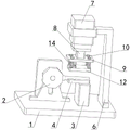
FIG. 1 is a schematic structural view of the present invention;
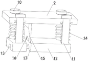
FIG. 2 is a schematic front sectional view of the present invention;
FIG. 3 is a schematic side sectional view of the present invention;
FIG. 4 is a schematic cross-sectional view of the inside of the round bar of the present invention;
fig. 5 is a partially enlarged structural view of a portion a in fig. 3.
In the figure: 1. a base; 2. a feeding mechanism; 3. a fixed block; 4. a first clamping block; 5. a first groove; 6. a support; 7. a sliding table pneumatic cylinder; 8. connecting blocks; 9. a connecting plate; 10. a round block; 11. a round bar; 12. a second clamping block; 13. a second groove; 14. a flexible spring; 15. cutting a cutter; 16. a slot; 17. a notch; 18. and (4) emptying the groove.
Detailed Description
The technical solutions in the embodiments of the present invention will be described clearly and completely with reference to the accompanying drawings in the embodiments of the present invention, and it is obvious that the described embodiments are only some embodiments of the present invention, not all embodiments. Based on the embodiments in the present invention, all other embodiments obtained by a person skilled in the art without creative work belong to the protection scope of the present invention.
As shown in fig. 1 to 5, the utility model provides a can press from both sides automatically and seal thin wall pipe mechanism, including base 1, the left side fixed mounting at base 1 top has feed mechanism 2, the middle part fixedly connected with fixed block 3 on base 1 top, top fixedly connected with clamp splice 4 of fixed block 3, the middle part on 4 tops of clamp splice is seted up fluted one 5, the top fixedly connected with of base 1 is located the support 6 on fixed block 3 right side, the inside fixed slip table pneumatic cylinder 7 that has cup jointed on support 6 top, the bottom fixedly connected with connecting block 8 of slip table pneumatic cylinder 7, the bottom fixedly connected with connecting plate 9 of connecting block 8, four equal swing joint in corner of connecting plate 9 top have round block 10, the bottom fixedly connected with round bar 11 of round block 10, the other end of round bar 11 runs through connecting plate 9 and extends to the outside of connecting plate 9 and fixedly connected with clamp splice two 12, recess two 13 has been seted up to the middle part of clamp splice two 12 bottom, the outside activity of round bar 11 has cup jointed the flexible spring 14 that is located between connecting plate 9 and the clamp splice two 12, thereby the top of flexible spring 14 will be in the contact with the clamp splice 14 and the flexible clamp splice 14, thereby make the top of the flexible spring 14 take place the flexible clamp splice and resume the flexible clamp splice two flexible clamp splice 14 and the flexible clamp splice takes place the downward when the flexible contact of the flexible clamp splice 14 and the flexible clamp splice two, thereby the flexible clamp splice 14, the top of the flexible clamp splice takes place the flexible clamp splice 14 and the flexible clamp splice 14, and the flexible clamp splice takes place the flexible clamp splice 14.
Referring to fig. 4, the number of the round bars 11 is four, two of the four round bars 11 form a group, and a cutting tool 15 located between the two groups of the round bars 11 is fixedly installed on the left side of the bottom of the connecting plate 9.
As the utility model discloses a technical optimization scheme, through cutting tool 15's design, when clamp splice one 4 and clamp splice two 12 press from both sides tight the thin wall pipe, the downstream of connecting plate 9 will make cutting tool 15 take place the downstream to make cutting tool 15 can cut the thin wall pipe, can cut the thin wall pipe when making the device press from both sides to seal the thin wall pipe.
Referring to fig. 4, a slot 16 is formed in the middle of the bottom end of the cutter 15, and the shape of the slot 16 is semicircular.
As a technical optimization scheme of the utility model, through slotted hole 16's design, slotted hole 16's diameter is the same with the diameter of thin wall pipe, consequently can be so that cutting tool 15 when cutting the thin wall pipe, can be so that the atress of cutting plane is more even to can reduce the deflection of cutting plane.
Referring to fig. 4, the second clamping block 12 is provided with a notch 17 therein, which is located below the cutting tool 15, and the size of the notch 17 is larger than that of the top of the cutting tool 15.
As a technical optimization scheme of the utility model, through notch 17's design for cutting tool 15 can pass the inside of clamp splice two 12, thereby cuts the thin wall pipe that is located clamp splice two 12 below, and notch 17 can not cause the influence to cutting tool 15's motion, thereby makes things convenient for cutting tool 15's cutting operation.
Referring to fig. 5, a hollow groove 18 located below the notch 17 is formed in the first clamping block 4, and the size of the hollow groove 18 is the same as that of the notch 17.
As a technical optimization scheme of the utility model, through the design of dead slot 18, when cutting tool 15 cuts the thin wall pipe, cutting tool 15's bottom will enter into the inside to dead slot 18, and cutting tool 15 can cut the thin wall pipe completely this moment to accomplish the cutting operation to the thin wall pipe.
Referring to fig. 5, the first groove 5 and the second groove 13 are semicircular in shape, the diameters of the first groove 5 and the second groove 13 are the same as the diameter of the thin-walled tube, and the inner walls of the first groove 5 and the second groove 13 are rough.
As the utility model discloses a technical optimization scheme, through the design of recess one 5 and two 13, when the bottom of thin wall pipe was located recess one 5's inside, the motion of clamp splice two 12 will make the top of thin wall pipe be located recess two 13's inside, through the cooperation between recess one 5 and the recess two 13, can play good tight effect of clamp to the thin wall pipe to make cutting tool 15's cutting position accurate.
The utility model discloses a theory of operation and use flow:
firstly, the thin-walled tube can move to the upper side of the first clamping block 4 through the feeding mechanism 2, so that the bottom of the thin-walled tube is located inside the first groove 5, then an operator starts the sliding table pneumatic cylinder 7, the operation of the sliding table pneumatic cylinder 7 enables the whole connecting plate 9 to move downwards through the connecting block 8 until the bottom of the second clamping block 12 is in contact with the top of the first clamping block 4, at the moment, the second clamping block 12 is limited, but the connecting plate 9 continues to move downwards, the flexible spring 14 is in a compressed state due to the movement of the connecting plate 9, and due to the elastic force recovery effect of the flexible spring 14, the flexible spring 14 can push the second clamping block 12, so that the first clamping block 4 and the second clamping block 12 are tightly attached, the thin-walled tube is tightly clamped inside the first groove 5 and the second groove 13, and the thin-walled tube is automatically clamped.
Then, the downward movement of the connecting plate 9 will make the cutting tool 15 move downward, so that the slotted hole 16 can cut the thin-walled tube through the inside of the slot opening 17 and the empty slot 18, and the slotted hole 16 can be attached to the outer surface of the thin-walled tube, so that the stress of the thin-walled tube on the circumferential surface is more uniform, and the deformation of the cutting section is reduced.
It is noted that, herein, relational terms such as first and second, and the like may be used solely to distinguish one entity or action from another entity or action without necessarily requiring or implying any actual such relationship or order between such entities or actions. Also, the terms "comprises," "comprising," or any other variation thereof, are intended to cover a non-exclusive inclusion, such that a process, method, article, or apparatus that comprises a list of elements does not include only those elements but may include other elements not expressly listed or inherent to such process, method, article, or apparatus.
Although embodiments of the present invention have been shown and described, it will be appreciated by those skilled in the art that changes, modifications, substitutions and alterations can be made in these embodiments without departing from the principles and spirit of the invention, the scope of which is defined in the appended claims and their equivalents.
Claims (6)
1. The utility model provides a can automatic press from both sides and seal thin wall pipe mechanism, includes base (1), its characterized in that: the spring clamp is characterized in that a feeding mechanism (2) is fixedly mounted on the left side of the top of the base (1), a fixed block (3) is fixedly connected to the middle of the top of the base (1), a first clamping block (4) is fixedly connected to the top of the fixed block (3), a first groove (5) is formed in the middle of the top of the first clamping block (4), a support (6) positioned on the right side of the fixed block (3) is fixedly connected to the top of the base (1), a sliding table pneumatic cylinder (7) is fixedly sleeved on the inside of the top of the support (6), a connecting block (8) is fixedly connected to the bottom of the sliding table pneumatic cylinder (7), a connecting plate (9) is fixedly connected to the bottom of the connecting block (8), two grooves (13) are formed in the middle of the two clamping blocks (12), a round rod (11) is fixedly connected to the bottom of the round rod (10), the other end of the round rod (11) penetrates through the connecting plate (9) and extends to the outside of the connecting plate (9), a second clamping block (12) is fixedly connected to the bottom of the spring (14), and one end of the flexible connecting plate (14) is connected to one end of the spring (9), the other end of the flexible spring (14) is fixedly connected with the top of the second clamping block (12).
2. A mechanism for automatically clamping and sealing thin-walled tube according to claim 1, wherein: the quantity of round bar (11) is four, four two of round bar (11) are a set of, the left side fixed mounting of connecting plate (9) bottom has cutting tool (15) that are located between two sets of round bar (11).
3. The thin-walled tube clamping and sealing mechanism according to claim 2, wherein: the middle part of the bottom end of the cutting tool (15) is provided with a slotted hole (16), and the shape of the slotted hole (16) is semicircular.
4. A mechanism for automatically clamping and sealing thin-walled tube according to claim 1, wherein: a notch (17) located below the cutting tool (15) is formed in the second clamping block (12), and the size of the notch (17) is larger than that of the top of the cutting tool (15).
5. The thin-walled tube clamping and sealing mechanism according to claim 1, wherein: an empty groove (18) located below the notch (17) is formed in the first clamping block (4), and the size of the empty groove (18) is the same as that of the notch (17).
6. A mechanism for automatically clamping and sealing thin-walled tube according to claim 1, wherein: the shapes of the first groove (5) and the second groove (13) are semicircular, the diameters of the first groove (5) and the second groove (13) are the same as the diameter of the thin-walled tube, and the inner walls of the first groove (5) and the second groove (13) are rough.
Priority Applications (1)
| Application Number | Priority Date | Filing Date | Title |
|---|---|---|---|
| CN202222300329.2U CN218016136U (en) | 2022-08-30 | 2022-08-30 | Thin-walled pipe mechanism capable of automatically clamping and sealing |
Applications Claiming Priority (1)
| Application Number | Priority Date | Filing Date | Title |
|---|---|---|---|
| CN202222300329.2U CN218016136U (en) | 2022-08-30 | 2022-08-30 | Thin-walled pipe mechanism capable of automatically clamping and sealing |
Publications (1)
| Publication Number | Publication Date |
|---|---|
| CN218016136U true CN218016136U (en) | 2022-12-13 |
Family
ID=84351565
Family Applications (1)
| Application Number | Title | Priority Date | Filing Date |
|---|---|---|---|
| CN202222300329.2U Active CN218016136U (en) | 2022-08-30 | 2022-08-30 | Thin-walled pipe mechanism capable of automatically clamping and sealing |
Country Status (1)
| Country | Link |
|---|---|
| CN (1) | CN218016136U (en) |
Cited By (1)
| Publication number | Priority date | Publication date | Assignee | Title |
|---|---|---|---|---|
| CN116900681A (en) * | 2023-09-04 | 2023-10-20 | 上海芬能自动化技术股份有限公司 | Positioning guide mechanism |
-
2022
- 2022-08-30 CN CN202222300329.2U patent/CN218016136U/en active Active
Cited By (2)
| Publication number | Priority date | Publication date | Assignee | Title |
|---|---|---|---|---|
| CN116900681A (en) * | 2023-09-04 | 2023-10-20 | 上海芬能自动化技术股份有限公司 | Positioning guide mechanism |
| CN116900681B (en) * | 2023-09-04 | 2024-04-19 | 上海芬能自动化技术股份有限公司 | Positioning guide mechanism |
Similar Documents
| Publication | Publication Date | Title |
|---|---|---|
| CN218016136U (en) | Thin-walled pipe mechanism capable of automatically clamping and sealing | |
| CN216540376U (en) | Continuous stamping die for forming aluminum shell | |
| CN105598687A (en) | Automatic production line for medical supplies | |
| CN111745060B (en) | Automatic material clamping hydraulic type corner impacting machine for aluminum processing | |
| CN208928937U (en) | A kind of tubing hemming device | |
| CN215745752U (en) | Metal product stamping forming machine with high automation degree | |
| CN112024677A (en) | Automatic flanging equipment for stainless steel lined composite steel pipe | |
| CN216990115U (en) | Cutting equipment for preventing steel pipe from deforming | |
| CN214981271U (en) | Hose head-injection machine blank device | |
| CN215920669U (en) | Silicon rubber production is with deciding thickness slitting device | |
| CN217346258U (en) | Plastic mold device convenient to fix | |
| CN213256486U (en) | Stamping device is used in panel board processing | |
| CN218982903U (en) | Pipe fitting opposite-punching forming die | |
| CN216781988U (en) | Thin-wall plastic pipe cutting device | |
| CN212331138U (en) | Steel wire reinforced hose shearing device | |
| CN217044233U (en) | High-precision hydraulic punching device for guardrail production | |
| CN211307513U (en) | Automobile gasket forming device | |
| CN218362112U (en) | Processing device for special-shaped groove product of pipe joint | |
| CN220862451U (en) | Bone wrapping and edge pressing device for luggage production | |
| CN214393055U (en) | Mounting rack for pipeline welding | |
| CN210305346U (en) | Bending die for circular groove of air valve | |
| CN215151977U (en) | Adhesive tape joint device | |
| CN216027354U (en) | Thin top device of cold extrusion machine | |
| CN217800399U (en) | Automatic processing flexible production line for tubular beam products | |
| CN212494945U (en) | Self-locking bending punching machine |
Legal Events
| Date | Code | Title | Description |
|---|---|---|---|
| GR01 | Patent grant | ||
| GR01 | Patent grant |