CN218011842U - Water-controlled dust remover for powder dust purification treatment - Google Patents
Water-controlled dust remover for powder dust purification treatment Download PDFInfo
- Publication number
- CN218011842U CN218011842U CN202222509231.8U CN202222509231U CN218011842U CN 218011842 U CN218011842 U CN 218011842U CN 202222509231 U CN202222509231 U CN 202222509231U CN 218011842 U CN218011842 U CN 218011842U
- Authority
- CN
- China
- Prior art keywords
- dust
- wall
- water
- box body
- box
- Prior art date
- Legal status (The legal status is an assumption and is not a legal conclusion. Google has not performed a legal analysis and makes no representation as to the accuracy of the status listed.)
- Active
Links
- 239000000428 dust Substances 0.000 title claims abstract description 112
- XLYOFNOQVPJJNP-UHFFFAOYSA-N water Substances O XLYOFNOQVPJJNP-UHFFFAOYSA-N 0.000 title claims abstract description 82
- 238000000746 purification Methods 0.000 title claims abstract description 21
- 239000000843 powder Substances 0.000 title claims abstract description 19
- 230000005484 gravity Effects 0.000 claims abstract description 9
- 230000005540 biological transmission Effects 0.000 claims description 21
- 238000002347 injection Methods 0.000 claims description 16
- 239000007924 injection Substances 0.000 claims description 16
- 239000007921 spray Substances 0.000 claims description 16
- 206010010904 Convulsion Diseases 0.000 claims description 7
- 230000036461 convulsion Effects 0.000 claims description 7
- 239000004744 fabric Substances 0.000 claims description 6
- 238000010030 laminating Methods 0.000 claims description 6
- 239000000463 material Substances 0.000 claims description 6
- 238000005507 spraying Methods 0.000 claims description 6
- 239000002351 wastewater Substances 0.000 claims description 4
- 230000008676 import Effects 0.000 claims 1
- 230000000694 effects Effects 0.000 abstract description 5
- 239000012535 impurity Substances 0.000 abstract description 5
- 238000007790 scraping Methods 0.000 description 6
- 239000003651 drinking water Substances 0.000 description 4
- 235000020188 drinking water Nutrition 0.000 description 4
- 238000010586 diagram Methods 0.000 description 3
- 238000007599 discharging Methods 0.000 description 3
- 238000000034 method Methods 0.000 description 3
- 239000002245 particle Substances 0.000 description 3
- 239000002699 waste material Substances 0.000 description 3
- 238000004140 cleaning Methods 0.000 description 2
- 238000003780 insertion Methods 0.000 description 2
- 230000037431 insertion Effects 0.000 description 2
- UGFAIRIUMAVXCW-UHFFFAOYSA-N Carbon monoxide Chemical compound [O+]#[C-] UGFAIRIUMAVXCW-UHFFFAOYSA-N 0.000 description 1
- 239000003570 air Substances 0.000 description 1
- 230000009286 beneficial effect Effects 0.000 description 1
- 238000001914 filtration Methods 0.000 description 1
- 239000003546 flue gas Substances 0.000 description 1
- 239000007789 gas Substances 0.000 description 1
- 230000003116 impacting effect Effects 0.000 description 1
- 239000007788 liquid Substances 0.000 description 1
- 230000001151 other effect Effects 0.000 description 1
- 238000005086 pumping Methods 0.000 description 1
- 238000011403 purification operation Methods 0.000 description 1
- 238000004064 recycling Methods 0.000 description 1
- 238000007789 sealing Methods 0.000 description 1
- 239000000243 solution Substances 0.000 description 1
- 230000001360 synchronised effect Effects 0.000 description 1
Images


Landscapes
- Filtering Of Dispersed Particles In Gases (AREA)
Abstract
The utility model discloses a water control dust remover for purifying powder dust, which comprises a box body and an air draft assembly fixedly arranged at the top of one end of the box body, wherein the inner wall of the box body is rotationally connected with a turntable, the outer wall of the turntable is attached to the inner wall of the box body, a water chute is arranged at the middle position of the turntable, a filter screen plate is fixed at the middle position of the water chute, a driving mechanism for driving the turntable to rotate is fixedly arranged at one side of the box body, a discharge opening is arranged at the other end of the box body, and a discharge hopper attached to the outer wall of the turntable is fixed on the inner wall of the discharge opening; the utility model discloses a meet water purification's effect to the powder raise dust to make the dust in the guiding gutter fall into the discharge hopper and discharge under the effect of independently gliding and gravity ball striking filter plate, thereby make whole water accuse dust remover be provided with the structure of better clearance dust impurity, avoid the dust to mix completely in aqueous.
Description
Technical Field
The utility model relates to a dust removal technical field specifically is a water accuse dust remover for powder raise dust purification treatment.
Background
The water-controlled dust collector is a device which makes dusty gas closely contact with liquid, utilizes the inertial collision and other effects of water drops and particles to collect particles or increase the particles, is a device which separates dust from flue gas and is called dust collector or dust collecting device, when powder is processed, powder raise dust can be generated, in order to avoid the pollution of the operation environment, the dust collection treatment is needed, and the water-controlled dust collector is often applied in the field.
At present, when purifying the dust raise dust through water accuse dust remover, be not provided with better clearance dust impurity's structure for the dust mixes in aqueous completely, in follow-up purification process, can not effectual purification operation, consequently, the urgent need of design a water accuse dust remover for dust raise dust purification treatment solves above-mentioned problem.
SUMMERY OF THE UTILITY MODEL
An object of the utility model is to provide a water accuse dust remover for powder raise dust purification treatment to solve the problem that proposes in the above-mentioned background art.
In order to achieve the above object, the utility model provides a following technical scheme:
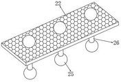
a water control dust collector for purifying powder dust comprises a box body and an air draft assembly fixedly mounted at the top of one end of the box body, wherein the inner wall of the box body is rotatably connected with a rotary table, the outer wall of the rotary table is attached to the inner wall of the box body, a water guide groove is formed in the middle of the rotary table, a filter screen plate is fixed in the middle of the water guide groove, a driving mechanism for driving the rotary table to rotate is fixedly mounted on one side of the box body, a discharge opening is formed in the other end of the box body, a discharge hopper attached to the outer wall of the rotary table is fixed on the inner wall of the discharge opening, movable holes are formed in the middle of the filter screen plate and are distributed at equal intervals, movable inserting rods are inserted into the inner walls of the movable holes, and gravity balls are fixed at the top end and the bottom end of each movable inserting rod;
and a spraying assembly is arranged on the other side of the box body and used for purifying the raised dust when encountering water.
Preferably, the air draft subassembly is including fixing the support frame in box one end, and one side fixed mounting of support frame has the air exhauster, and the air draft end fixed mounting of air exhauster has the suction hood, the air intake has been seted up at the one end top of box, and the inner wall of air intake and the air exhaust end fixed mounting of air exhauster have the air inlet cover.
Preferably, the spray assembly includes the suction pump of fixed mounting at box opposite side outer wall, and the bottom fixed mounting of suction pump has the drinking-water pipe of pegging graft in the box, and the opposite side inner wall fixed mounting of box has the filter mantle of parcel in drinking-water pipe one end, the top fixed mounting of suction pump has the drain pipe of pegging graft top in the box, and the one end of drain pipe is fixed with the shower, and the bottom fixed mounting of shower has the shower nozzle that the equidistance distributes.
Preferably, a connecting hole is formed in one side of the box body, the inner wall of the connecting hole is connected with a transmission shaft through a sealing bearing, and a scraping rod attached to the outer wall of the filter cover is fixed at one end of the transmission shaft.
Preferably, the driving mechanism comprises a frame fixedly installed on the outer wall of one side of the box body, a stepping motor used for driving the turntable to rotate is fixedly installed on one side of the frame, a driving wheel is fixedly installed at the other end of an output shaft of the stepping motor and the other end of the transmission shaft, and a driving belt is connected to the outer wall of the driving wheel in a driving mode.
Preferably, a water injection pipe and a waste water pipe are respectively fixed on one side of the box body, valves are fixedly mounted on the water injection pipe and the waste water pipe, and supporting angle seats are fixed at two ends of the bottom of the box body.
Preferably, the exit has been seted up to the one end of box, and the inner wall of importing and exporting is pegged graft and is had the pull frame, and the pull frame is located the top of water injection pipe, and the notch has been seted up to the bottom intermediate position of pull frame, and the inner wall fixed mounting of notch has collection dirt cloth, the both ends inner wall of box all is fixed with the backup pad of laminating in the pull frame bottom, and the one end of pull frame is fixed with the handle bar, and the one end outer wall both sides of box all rotate and are connected with the locking plate of laminating in pull frame one end.
Compared with the prior art, the beneficial effects of the utility model are that:
the utility model discloses in, through the box that sets up, the convulsions subassembly, spray set, actuating mechanism, the carousel, guiding gutter and filter plate form the water accuse dust remover that is used for powder raise dust purification treatment, when removing dust, utilize spray set to spray the water of bottom half at the top of box, and make it flow back to the bottom of box through guiding gutter and filter plate, the air suction that will have the powder raise dust through convulsions subassembly at this moment is in the box, open the valve of water injection pipe, make the dust purify when meeting water in the spraying process, and make air and dust and water fall into the guiding gutter, filter treatment is carried out to the dust through filter plate, make the dust pile up gradually at the top of guiding gutter, and the air is then discharged through the water injection pipe, the effect of meeting water purification to the powder raise dust has been realized;
the utility model discloses in, treat to purify behind the period, utilize step motor in the actuating mechanism to drive carousel and transmission shaft synchronous revolution one hundred eighty degrees, turn around the guiding gutter, when the guiding gutter is rotatory to discharge hopper one side, the dust in the guiding gutter will be discharged in falling into the discharge hopper under the effect of independently gliding and gravity ball striking filter plate, thereby make whole water accuse dust remover be provided with the structure of better clearance dust impurity, avoid the dust to mix completely in aqueous, moreover, the transmission shaft will drive when rotatory and scrape the material pole and rotate in one side of filter mantle, the utilization is scraped the material pole and is cleared up spray assembly's filter mantle, avoid spray assembly to appear the problem of jam.
Drawings
Fig. 1 is a schematic diagram of the overall structure of a water-controlled dust collector for purifying dust.
Fig. 2 is a schematic rear view of a water-controlled dust collector for dust purification treatment of dust.
Fig. 3 is an overall sectional view of a water control dust collector for dust emission purification treatment of powder.
Fig. 4 is a schematic structural view of a drawing frame and a dust collecting cloth of a water control dust collector for purifying powder dust.
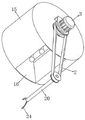
Fig. 5 is a schematic structural diagram of a rotary disc and a scraping rod of a water-controlled dust collector for purifying dust.
Fig. 6 is a schematic structural diagram of a filter screen plate and a gravity ball of a water control dust collector for purifying dust.
In the figure: 1. a box body; 2. a transmission belt; 3. a stepping motor; 4. a support frame; 5. an air draft cover; 6. an exhaust fan; 7. a drain pipe; 8. a discharge hopper; 9. a water injection pipe; 10. a water pump; 11. a water pumping pipe; 12. drawing the frame; 13. a lock plate; 14. an air inlet cover; 15. a turntable; 16. a water chute; 17. a shower pipe; 18. a spray head; 19. a filter housing; 20. a drive shaft; 21. a dust collecting cloth; 22. a filter screen plate; 23. a support plate; 24. a scraping rod; 25. a gravity ball; 26. a movable inserted link.
Detailed Description
The technical solutions in the embodiments of the present invention will be described clearly and completely with reference to the accompanying drawings in the embodiments of the present invention, and it is obvious that the described embodiments are only some embodiments of the present invention, not all embodiments. Based on the embodiments in the present invention, all other embodiments obtained by a person skilled in the art without creative work belong to the protection scope of the present invention.
Example 1
Referring to fig. 1-6, in an embodiment of the present invention, a water-controlled dust collector for purifying and processing dust from powder comprises a box body 1 and an air draft assembly fixedly installed at the top of one end of the box body 1, the inner wall of the box body 1 is rotatably connected with a turntable 15, the outer wall of the turntable 15 is attached to the inner wall of the box body 1, a water chute 16 is disposed at the middle position of the turntable 15, a filter screen plate 22 is fixed at the middle position of the water chute 16, a driving mechanism for driving the turntable 15 to rotate is fixedly installed at one side of the box body 1, a discharge opening is disposed at the other end of the box body 1, a discharge hopper 8 attached to the outer wall of the turntable 15 is fixed to the inner wall of the discharge opening, movable holes are disposed at the middle position of the filter screen plate 22 and distributed equidistantly, movable insertion rods 26 are inserted into the inner walls of the movable holes, gravity balls 25 are fixed at the top end and the bottom end of the movable insertion rods 26, the rotary table 15 is driven to rotate eighty degrees by the driving mechanism, the water chute 16 is turned around, when the water chute 16 rotates to one side of the discharge hopper 8, dust falling under the gravity balls 25, and impurities are prevented from falling into the filter screen plate 22, and the dust-controlled dust collector, and the dust is completely discharged from the dust collector;
the other side of the box body 1 is provided with a spraying assembly for purifying the raised dust when encountering water.
Further, the convulsions subassembly is including fixing support frame 4 in box 1 one end, and one side fixed mounting of support frame 4 has air exhauster 6, and the convulsions end fixed mounting of air exhauster 6 has exhaust cover 5, and the air intake has been seted up at the one end top of box 1, and the inner wall of air intake and the air exhaust end fixed mounting of air exhauster 6 have air inlet cover 14, through the air suction subassembly with the air suction that has the powder raise dust to box 1 in, the purification treatment of being convenient for.
Further, spray assembly includes suction pump 10 of fixed mounting at box 1 opposite side outer wall, and the bottom fixed mounting of suction pump 10 has the drinking-water pipe 11 of pegging graft in box 1, the opposite side inner wall fixed mounting of box 1 has the filter mantle 19 of parcel in drinking-water pipe 11 one end, the top fixed mounting of suction pump 10 has the drain pipe 7 of pegging graft top in box 1, and the one end of drain pipe 7 is fixed with shower 17, the bottom fixed mounting of shower 17 has the shower nozzle 18 of equidistance distribution, utilize spray assembly to spout the water of box 1 bottom at the top of box 1, make the dust meet the water purification at the in-process that sprays.
Further, the connecting hole has been seted up to one side of box 1, and the inner wall of connecting hole is connected with transmission shaft 20 through sealed bearing, and the one end of transmission shaft 20 is fixed with the laminating and scrapes material pole 24 at 19 outer walls of filter mantle, and transmission shaft 20 will drive when rotatory and scrape material pole 24 and rotate in one side of filter mantle 19, utilizes to scrape material pole 24 and clears up spray assembly's filter mantle 19, avoids spray assembly to appear the problem of jam.
Furthermore, the driving mechanism comprises a rack fixedly installed on the outer wall of one side of the box body 1, a stepping motor 3 used for driving the turntable 15 to rotate is fixedly installed on one side of the rack, a driving wheel is fixedly installed on the output shaft of the stepping motor 3 and the other end of the transmission shaft 20, a transmission belt 2 is connected to the outer wall of the transmission wheel in a transmission mode, the transmission shaft 20 is driven by the driving mechanism and the transmission belt 2 to rotate synchronously with the turntable 15, and electric power is saved.
Further, one side of box 1 is fixed with water injection pipe 9 and waste pipe respectively, and on the water injection pipe 9 and on the waste pipe equal fixed mounting have a valve, the bottom both ends of box 1 all are fixed with the support angle seat, and accessible water injection pipe 9 and waste pipe carry out water injection drainage operation.
Example 2
Please refer to fig. 1, fig. 2, fig. 3 and fig. 4, the difference from the embodiment 1 is that an inlet and an outlet are formed at one end of the box body 1, a drawing frame 12 is inserted into an inner wall of the inlet and the outlet, the drawing frame 12 is located above the water injection pipe 9, a notch is formed in the middle position of the bottom of the drawing frame 12, a dust collecting cloth 21 is fixedly installed on an inner wall of the notch, supporting plates 23 attached to the bottom of the drawing frame 12 are fixed on inner walls at two ends of the box body 1, a handle rod is fixed at one end of the drawing frame 12, a locking plate 13 attached to one end of the drawing frame 12 is rotatably connected to two sides of an outer wall at one end of the box body 1, when dust, air and moisture fall from the water guiding groove 16, secondary filtering operation is performed on the raised dust through the drawing frame 12 and the dust collecting cloth 21, so that the raised dust can be sufficiently collected and processed, and recycling of the moisture is facilitated.
The utility model discloses a theory of operation is: when dust is removed, water in the bottom of the box body 1 is sprayed to the top of the box body 1 through the spraying component and flows back to the bottom of the box body 1 through the water guiding groove 16 and the filter screen plate 22, air with powder dust is sucked into the box body 1 through the air draft component at the moment, a valve of the water injection pipe 9 is opened, dust is purified when meeting water in the spraying process, the air, the dust and the water fall into the water guiding groove 16, the dust is filtered through the filter screen plate 22, the dust is gradually accumulated on the top of the water guiding groove 16, the air is discharged through the water injection pipe 9, the effect of purifying the powder dust when meeting water is achieved, after the dust is purified for a period of time, the step motor 3 in the driving mechanism is used for driving the rotary disc 15 and the transmission shaft 20 to synchronously rotate for one hundred eighty degrees, the water guiding groove 16 is turned around, when the water guiding groove 16 rotates to one side of the filter screen plate 22, the dust in the water guiding groove 16 falls into the discharging hopper 8 under the action of self-gliding and the action of the gravity ball 25 impacting the filter screen plate 22 to discharge the dust, the dust is discharged, the whole water control dust remover is provided with a better discharging dust cleaning device, impurities in the discharging hopper 16, the dust cleaning structure, the filter screen bar is prevented from being blocked when the filter rod is sprayed, and the filter screen bar scraping component 19, and the filter bar scraping component is completely, and the filter bar scraping component is prevented from rotating when the filter bar 24 rotates.
It will be evident to those skilled in the art that the invention is not limited to the details of the foregoing illustrative embodiments, and that the present invention may be embodied in other specific forms without departing from the spirit or essential attributes thereof.
Claims (7)
1. The utility model provides a water accuse dust remover for powder raise dust purification treatment, includes box (1) and the convulsions subassembly of fixed mounting at box (1) one end top, the inner wall of box (1) rotates and is connected with carousel (15), and the outer wall of carousel (15) laminates with the inner wall of box (1) mutually, guiding gutter (16) have been seted up to the intermediate position of carousel (15), and the intermediate position of guiding gutter (16) is fixed with filter plate (22), its characterized in that: a driving mechanism for driving the rotary table (15) to rotate is fixedly installed on one side of the box body (1), a discharge opening is formed in the other end of the box body (1), a discharge hopper (8) attached to the outer wall of the rotary table (15) is fixed to the inner wall of the discharge opening, movable holes distributed at equal intervals are formed in the middle of the filter screen plate (22), movable inserting rods (26) are inserted into the inner walls of the movable holes, and gravity balls (25) are fixed to the top ends and the bottom ends of the movable inserting rods (26);
the other side of box (1) is provided with spraying assembly for the water purification treatment of raise dust.
2. The water-controlled dust collector for dust purification treatment of the dust according to claim 1, wherein: the convulsions subassembly is including fixing support frame (4) in box (1) one end, and one side fixed mounting of support frame (4) has air exhauster (6), and the convulsions end fixed mounting of air exhauster (6) has exhaust hood (5), the air intake has been seted up at the one end top of box (1), and the inner wall of air intake and the air exhaust end fixed mounting of air exhauster (6) have air inlet cover (14).
3. The water-controlled dust collector for dust purification treatment of the dust according to claim 2, characterized in that: the spray assembly comprises a water suction pump (10) fixedly installed on the outer wall of the other side of the box body (1), a water suction pipe (11) inserted in the box body (1) is fixedly installed at the bottom of the water suction pump (10), a filter cover (19) wrapped at one end of the water suction pipe (11) is fixedly installed on the inner wall of the other side of the box body (1), a drain pipe (7) inserted in the top of the box body (1) is fixedly installed at the top of the water suction pump (10), a spray pipe (17) is fixed to one end of the drain pipe (7), and spray heads (18) distributed equidistantly are fixedly installed at the bottom of the spray pipe (17).
4. The water-controlled dust collector for dust purification treatment of the dust according to claim 3, wherein: the connecting hole is opened to one side of box (1), and the inner wall of connecting hole is connected with transmission shaft (20) through sealed bearing, and the one end of transmission shaft (20) is fixed with laminating and scrapes material pole (24) at filter mantle (19) outer wall.
5. The water-controlled dust collector for dust purification treatment of the dust according to claim 4, wherein: the driving mechanism comprises a rack fixedly installed on the outer wall of one side of the box body (1), a stepping motor (3) used for driving the rotating disc (15) to rotate is fixedly installed on one side of the rack, a driving wheel is fixedly arranged at the other end of an output shaft of the stepping motor (3) and the other end of the transmission shaft (20), and a transmission belt (2) is connected to the outer wall of the driving wheel in a transmission mode.
6. The water-controlled dust collector for dust purification treatment of the dust according to claim 1, wherein: one side of the box body (1) is respectively fixed with a water injection pipe (9) and a waste water pipe, valves are fixedly mounted on the water injection pipe (9) and the waste water pipe, and supporting angle seats are fixed at two ends of the bottom of the box body (1).
7. The water-controlled dust collector for dust purification treatment of the dust according to claim 1, wherein: import and export have been seted up to the one end of box (1), and the inner wall of importing and exporting is pegged graft and is had pull frame (12), and pull frame (12) are located the top of water injection pipe (9), and the notch has been seted up to the bottom intermediate position of pull frame (12), and the inner wall fixed mounting of notch has collection dirt cloth (21), the both ends inner wall of box (1) all is fixed with backup pad (23) of laminating in pull frame (12) bottom, and the one end of pull frame (12) is fixed with the handle bar, and the one end outer wall both sides of box (1) all rotate and are connected with locking board (13) of laminating in pull frame (12) one end.
Priority Applications (1)
| Application Number | Priority Date | Filing Date | Title |
|---|---|---|---|
| CN202222509231.8U CN218011842U (en) | 2022-09-22 | 2022-09-22 | Water-controlled dust remover for powder dust purification treatment |
Applications Claiming Priority (1)
| Application Number | Priority Date | Filing Date | Title |
|---|---|---|---|
| CN202222509231.8U CN218011842U (en) | 2022-09-22 | 2022-09-22 | Water-controlled dust remover for powder dust purification treatment |
Publications (1)
| Publication Number | Publication Date |
|---|---|
| CN218011842U true CN218011842U (en) | 2022-12-13 |
Family
ID=84356162
Family Applications (1)
| Application Number | Title | Priority Date | Filing Date |
|---|---|---|---|
| CN202222509231.8U Active CN218011842U (en) | 2022-09-22 | 2022-09-22 | Water-controlled dust remover for powder dust purification treatment |
Country Status (1)
| Country | Link |
|---|---|
| CN (1) | CN218011842U (en) |
-
2022
- 2022-09-22 CN CN202222509231.8U patent/CN218011842U/en active Active
Similar Documents
| Publication | Publication Date | Title |
|---|---|---|
| CN220346157U (en) | Wet electrostatic precipitator | |
| CN218011842U (en) | Water-controlled dust remover for powder dust purification treatment | |
| CN219539828U (en) | Industrial smoke granulation recycling device | |
| CN216755894U (en) | Dust collecting equipment for recycling and reusing dust | |
| CN218687517U (en) | Environment-friendly waste gas treatment equipment | |
| CN217015966U (en) | Pneumatic mixing cyclone tower suitable for flue gas treatment | |
| CN214809455U (en) | Wet dust removal device for construction engineering construction | |
| CN214319627U (en) | Two-section type wet dust collector | |
| CN212881590U (en) | Workshop dust collecting device | |
| CN213590072U (en) | Energy-saving and environment-friendly equipment for waste gas treatment | |
| CN211536998U (en) | A water film deduster for betaine crystallization pollutant | |
| CN114593517A (en) | Efficient dedusting and filtering hospital ventilating duct | |
| CN114452755A (en) | Waste gas cooling and dust removing equipment for alloy smelting | |
| CN208878100U (en) | Air box impulse bag-type dust remover | |
| CN218281159U (en) | Desulfurization dust remover of water impact mode | |
| CN215822663U (en) | Wet dust collector | |
| CN221412585U (en) | Plastic particle granulation exhaust treatment equipment | |
| CN216259780U (en) | Dust collector for housing construction | |
| CN215965433U (en) | Smashing device for building decoration solid waste crusher | |
| CN220689742U (en) | Metal material smelting device | |
| CN213823975U (en) | Multifunctional wet dust collector | |
| CN212999166U (en) | Automatic change waste material dust collection device for processing | |
| CN221207368U (en) | Waste gas spraying filtration equipment that exhaust-gas treatment used | |
| CN211965303U (en) | Dust cleaning device for machining | |
| CN219682002U (en) | Waste gas purification environmental protection equipment |
Legal Events
| Date | Code | Title | Description |
|---|---|---|---|
| GR01 | Patent grant | ||
| GR01 | Patent grant |