CN218005684U - Low-voltage switch cabinet with anti-falling function - Google Patents
Low-voltage switch cabinet with anti-falling function Download PDFInfo
- Publication number
- CN218005684U CN218005684U CN202220760488.8U CN202220760488U CN218005684U CN 218005684 U CN218005684 U CN 218005684U CN 202220760488 U CN202220760488 U CN 202220760488U CN 218005684 U CN218005684 U CN 218005684U
- Authority
- CN
- China
- Prior art keywords
- drawer body
- drawer
- cabinet
- low
- guide
- Prior art date
- Legal status (The legal status is an assumption and is not a legal conclusion. Google has not performed a legal analysis and makes no representation as to the accuracy of the status listed.)
- Active
Links
Images


Landscapes
- Drawers Of Furniture (AREA)
Abstract
本实用新型公开了一种具有防跌落功能的低压开关柜,包括柜体和抽屉本体;所述柜体内间隔设置有隔板,所述抽屉本体设置在所述隔板上,所述抽屉本体与柜体之间设置有防跌落机构;所述防跌落机构包括安装在柜体内侧的导轨滑块组件,所述导轨滑块组件的滑块的端部滑动配合有连接块,所述连接块上设置有滑槽,所述抽屉本体的外侧固定安装有弹性插销,所述弹性插销与滑槽插接配合,所述弹性插销靠近滑块的一侧设置有斜面。本具有防跌落功能的低压开关柜具有结构简单,成本低,便于操作的优点。
The utility model discloses a low-voltage switchgear with the function of preventing falling, which comprises a cabinet body and a drawer body; partitions are arranged at intervals in the cabinet, the drawer body is arranged on the partition, and the drawer body and the An anti-drop mechanism is provided between the cabinets; the anti-drop mechanism includes a guide rail slider assembly installed inside the cabinet, and the end of the slider of the guide rail slider assembly is slidably fitted with a connecting block. A chute is provided, and an elastic pin is fixedly installed on the outside of the drawer body, and the elastic pin is plugged and matched with the chute, and a slope is provided on a side of the elastic pin close to the slider. The low-voltage switch cabinet with the anti-drop function has the advantages of simple structure, low cost and convenient operation.
Description
技术领域technical field
本实用新型涉及开关柜技术领域,特别是涉及一种具有防跌落功能的低压开关柜。The utility model relates to the technical field of switch cabinets, in particular to a low-voltage switch cabinet with the function of preventing falling.
背景技术Background technique
开关柜是一种电气设备,开关柜外线先进入柜内主控开关,然后进入分控开关,各分路按其需要设置。如仪表,自控,电动机磁力开关,各种交流接触器等,有的还设高压室与低压室开关柜,设有高压母线,如发电厂等,有的还设有为保主要设备的低周减载。开关柜的主要作用是在电力系统进行发电、输电、配电和电能转换的过程中,进行开合、控制和保护用电设备。开关柜内的部件主要有断路器、隔离开关、负荷开关、操作机构、互感器以及各种保护装置等组成。低压开关柜适用于发电厂、石油、化工、冶金、纺织、高层建筑等行业,作为输电、配电及电能转换之用。The switch cabinet is a kind of electrical equipment. The outside line of the switch cabinet first enters the main control switch in the cabinet, and then enters the sub-control switch. Each branch is set according to its needs. Such as instruments, automatic controls, motor magnetic switches, various AC contactors, etc., some also have high-voltage room and low-voltage room switch cabinets, high-voltage busbars, such as power plants, etc. load shedding. The main function of the switchgear is to open and close, control and protect electrical equipment during the process of power generation, transmission, distribution and power conversion in the power system. The components in the switch cabinet are mainly composed of circuit breakers, disconnectors, load switches, operating mechanisms, transformers and various protection devices. Low-voltage switchgear is suitable for power plants, petroleum, chemical industry, metallurgy, textiles, high-rise buildings and other industries, as power transmission, power distribution and power conversion.
低压开关柜包括柜体和设置在柜体内的抽屉本体,柜体和抽屉本体之间抽拉配合,如果开关柜与柜体之间没有防跌落机构,在抽出抽屉本体之后,抽屉本体容易跌落,导致抽屉本体上安装的部件受损;目前带有防跌落机构的开关柜,其在抽屉抽出一部分之后,需要手动解锁,然后将抽屉拉出,操作费时费力,结构复杂,不便于使用。The low-voltage switchgear includes a cabinet body and a drawer body installed in the cabinet body. The cabinet body and the drawer body are pulled together. If there is no anti-drop mechanism between the switch cabinet and the cabinet body, the drawer body is easy to fall after the drawer body is pulled out. The components installed on the drawer body are damaged; the current switchgear with the anti-drop mechanism needs to be manually unlocked after a part of the drawer is pulled out, and then the drawer is pulled out. The operation is time-consuming and laborious, the structure is complicated, and it is not easy to use.
发明内容Contents of the invention
针对上述现有技术的不足,本专利申请所要解决的技术问题是如何提供一种结构简单,成本低,便于操作的具有防跌落功能的低压开关柜。Aiming at the deficiencies in the prior art above, the technical problem to be solved in this patent application is how to provide a low-voltage switchgear with a simple structure, low cost, and easy to operate with anti-drop function.
为了解决上述技术问题,本实用新型采用了如下的技术方案:In order to solve the above technical problems, the utility model adopts the following technical solutions:
一种具有防跌落功能的低压开关柜,包括柜体和抽屉本体;所述柜体内间隔设置有隔板,所述抽屉本体设置在所述隔板上,所述抽屉本体与柜体之间设置有防跌落机构;A low-voltage switchgear with anti-drop function, comprising a cabinet body and a drawer body; partitions are arranged at intervals in the cabinet, the drawer body is arranged on the partition board, and the drawer body and the cabinet body are arranged There is an anti-drop mechanism;
所述防跌落机构包括安装在柜体内侧的导轨滑块组件,所述导轨滑块组件的滑块的端部滑动配合有连接块,所述连接块上设置有滑槽,所述抽屉本体的外侧固定安装有弹性插销,所述弹性插销与滑槽插接配合,所述弹性插销靠近滑块的一侧设置有斜面。The anti-drop mechanism includes a guide rail slider assembly installed inside the cabinet, the end of the slider of the guide rail slider assembly is slidably fitted with a connecting block, the connecting block is provided with a slide groove, and the drawer body An elastic bolt is fixedly installed on the outer side, and the elastic bolt is plugged and matched with the chute, and a slope is arranged on a side of the elastic bolt close to the slider.
这样,抽屉本体的外侧两端设置有把手,在向外拉动抽屉时,双手握持把手向外拉动抽屉,导轨滑块组件的滑块滑动到位后,连接块相对于滑块滑动到位后,弹性插销相对于滑槽滑动,此时抽屉本体已经位于柜体外侧,向上抬起抽屉本体,即可以将抽屉本体取出,可以实现一次性拉动到位后取出抽屉,中间无需手部松开把手。抽屉本体取出后,将防跌落组件推动至柜体内,在将抽屉本体放回时,将抽屉本体放置在隔板上,推动抽屉本体向内移动,弹性插销与连接块碰撞,在斜面的作用下,弹性插销缩回,当弹性插销与滑槽正对时,弹性插销复位插入滑槽内,实现与防跌落机构的连接,之后将抽屉本体推动到位即可。本申请的开关柜,在抽出抽屉后,向上抬起抽屉即可取出抽屉,可以更好的防止抽屉跌落。In this way, handles are provided at both ends of the drawer body. When the drawer is pulled outward, hold the handle with both hands to pull the drawer outward. After the slide block of the guide rail slider assembly slides in place, after the connecting block slides in place relative to the slide block, the elastic The latch slides relative to the chute. At this time, the drawer body is already on the outside of the cabinet body. Lift the drawer body upwards, and the drawer body can be taken out, and the drawer can be pulled out once it is in place. There is no need to release the handle by hand. After the drawer body is taken out, push the anti-drop assembly into the cabinet. When putting the drawer body back, place the drawer body on the partition, push the drawer body to move inward, and the elastic bolt collides with the connecting block. , the elastic pin is retracted, when the elastic pin is facing the chute, the elastic pin is reset and inserted into the chute to realize the connection with the anti-drop mechanism, and then push the drawer body into place. In the switchgear of the present application, after the drawer is drawn out, the drawer can be taken out by lifting the drawer upwards, which can better prevent the drawer from falling.
其中,所述导轨滑块组件包括固定安装在柜体内侧的两个耳座,两个支耳之间固定安装有两根间隔设置的导轨,所述滑块具有与导轨滑动配合的滑孔。滑块沿导轨滑动。Wherein, the guide rail slider assembly includes two ear seats fixedly installed on the inside of the cabinet, two guide rails arranged at intervals are fixedly installed between the two lugs, and the slide block has sliding holes for sliding fit with the guide rails. The slider slides along the rails.
其中,所述滑块的端部设置有导向槽,所述导向槽一侧设置有缺口,所述连接块的端部两侧向外凸出设置,所述连接块的端部与导向槽滑动配合;所述导向槽内固定安装有导向杆,所述连接块具有与导向杆滑动配合的导向孔。连接块端部呈T形,便于与滑块连接。可以更好的提供一个空间,便于抽屉本体更好的从柜体拖出。Wherein, the end of the slider is provided with a guide groove, one side of the guide groove is provided with a gap, the two sides of the end of the connecting block protrude outward, and the end of the connecting block slides with the guide groove Cooperate; a guide rod is fixedly installed in the guide groove, and the connecting block has a guide hole slidingly matched with the guide rod. The end of the connecting block is T-shaped, which is convenient for connecting with the slider. A space can be better provided, so that the drawer body can be better pulled out from the cabinet body.
其中,所述弹性插销包括固定安装在抽屉本体外侧的插座,所述插座具有向下开口设置的容纳槽,所述容纳槽内通过弹簧与插销连接,所述插销的上端与容纳槽滑动配合,所述插销对应滑块的一侧设置有斜面。Wherein, the elastic bolt includes a socket fixedly installed on the outside of the drawer body, the socket has a receiving groove opened downward, the inside of the receiving groove is connected to the bolt through a spring, and the upper end of the latch is slidingly matched with the receiving groove, A slope is provided on one side of the bolt corresponding to the slider.
其中,所述容纳槽截面为矩形,所述插销截面为矩形。对插销进行防转,使得斜面与滑块正对。Wherein, the cross-section of the receiving groove is rectangular, and the cross-section of the pin is rectangular. Anti-rotate the latch so that the ramp faces the slider.
其中,所述抽屉本体的两侧的上端和下端分别向外凸出设置有限位板,所述限位板与柜体滑动贴合。便于对抽屉本体进行左侧和右侧的限位。Wherein, the upper end and the lower end of both sides of the drawer body respectively protrude outwards to be provided with limiting plates, and the limiting plates are slidably attached to the cabinet body. It is convenient to limit the left and right sides of the drawer body.
综上,本具有防跌落功能的低压开关柜具有结构简单,成本低,便于操作的优点。To sum up, the low-voltage switchgear with the anti-drop function has the advantages of simple structure, low cost and easy operation.
附图说明Description of drawings
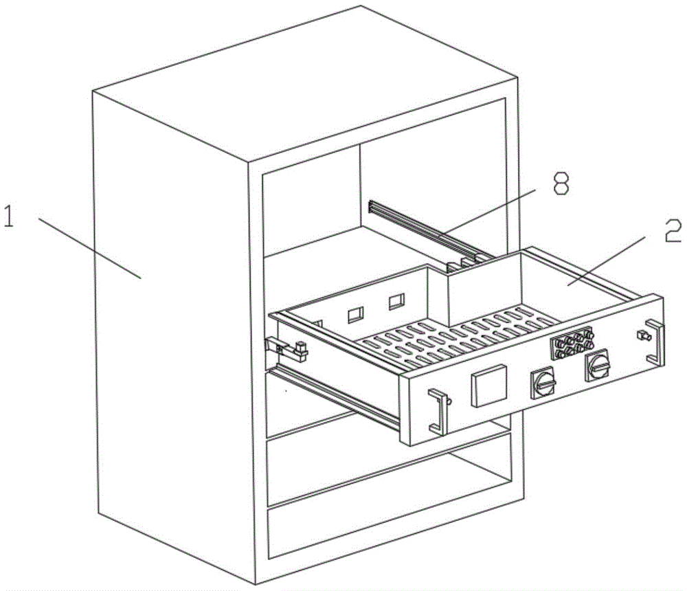
图1为本实用新型所述的一种具有防跌落功能的低压开关柜的结构示意图。Fig. 1 is a schematic structural diagram of a low-voltage switchgear with anti-drop function described in the present invention.
图2为图1的局部示意图,其中抽屉本体处于拉出状态。Fig. 2 is a partial schematic diagram of Fig. 1, wherein the drawer body is in a pulled-out state.
图3为抽屉本体的示意图。Fig. 3 is a schematic diagram of the drawer body.
图4为图3的局部示意图。FIG. 4 is a partial schematic diagram of FIG. 3 .
图5为图3处于拉出状态的示意图。Fig. 5 is a schematic diagram of Fig. 3 in a pulled-out state.
图6为图5的局部示意图。FIG. 6 is a partial schematic diagram of FIG. 5 .
图7为防跌落机构的剖视图。Fig. 7 is a sectional view of the anti-drop mechanism.
具体实施方式detailed description
下面结合附图对本实用新型作进一步的详细说明。在本实用新型的描述中,需要理解的是,方位词如“上、下”和“顶、底”等所指示的方位或位置关系通常是基于附图所示的方位或位置关系,仅是为了便于描述本实用新型和简化描述,在未作相反说明的情况下,这些方位词并不指示和暗示所指的装置或元件必须具有特定的方位或者以特定的方位构造和操作,因此不能理解为对本实用新型保护范围的限制;方位词“内、外”是指相对于各部件本身的轮廓的内外。Below in conjunction with accompanying drawing, the utility model is described in further detail. In the description of the present utility model, it should be understood that the orientations or positional relationships indicated by orientation words such as "up, down" and "top, bottom" are usually based on the orientations or positional relationships shown in the accompanying drawings, and are only In order to facilitate the description of the utility model and simplify the description, these orientation words do not indicate and imply that the device or element referred to must have a specific orientation or be constructed and operated in a specific orientation unless otherwise specified, so it cannot be understood To limit the protection scope of the present utility model; the orientation words "inner and outer" refer to the inside and outside of the outline of each component itself.
如图1-7所示,一种具有防跌落功能的低压开关柜,包括柜体1和抽屉本体2;所述柜体1内间隔设置有隔板,所述抽屉本体2设置在所述隔板上,隔板上设置有散热孔以及过线孔,所述抽屉本体2与柜体1之间设置有防跌落机构;As shown in Figure 1-7, a low-voltage switch cabinet with anti-drop function includes a
所述防跌落机构包括安装在柜体1内侧的导轨滑块组件,所述导轨滑块组件的滑块3的端部滑动配合有连接块4,所述连接块上设置有滑槽5,所述抽屉本体的外侧固定安装有弹性插销6,所述弹性插销与滑槽插接配合,所述弹性插销靠近滑块的一侧设置有斜面7。The anti-drop mechanism includes a guide rail slider assembly installed inside the
这样,抽屉本体的外侧两端设置有把手,在向外拉动抽屉时,双手握持把手向外拉动抽屉,导轨滑块组件的滑块滑动到位后,连接块相对于滑块滑动到位后,弹性插销相对于滑槽滑动,此时抽屉本体已经位于柜体外侧,向上抬起抽屉本体,即可以将抽屉本体取出,可以实现一次性拉动到位后取出抽屉,中间无需手部松开把手。抽屉本体取出后,将防跌落组件推动至柜体内,在将抽屉本体放回时,将抽屉本体放置在隔板上,推动抽屉本体向内移动,弹性插销与连接块碰撞,在斜面的作用下,弹性插销缩回,当弹性插销与滑槽正对时,弹性插销复位插入滑槽内,实现与防跌落机构的连接,之后将抽屉本体推动到位即可。本申请的开关柜,在抽出抽屉后,向上抬起抽屉即可取出抽屉,可以更好的防止抽屉跌落。In this way, handles are provided at both ends of the drawer body. When the drawer is pulled outward, hold the handle with both hands to pull the drawer outward. After the slide block of the guide rail slider assembly slides in place, after the connecting block slides in place relative to the slide block, the elastic The latch slides relative to the chute. At this time, the drawer body is already on the outside of the cabinet body. Lift the drawer body upwards, and the drawer body can be taken out, and the drawer can be pulled out once it is in place. There is no need to release the handle by hand. After the drawer body is taken out, push the anti-drop assembly into the cabinet. When putting the drawer body back, place the drawer body on the partition, push the drawer body to move inward, and the elastic bolt collides with the connecting block. , the elastic pin is retracted, when the elastic pin is facing the chute, the elastic pin is reset and inserted into the chute to realize the connection with the anti-drop mechanism, and then push the drawer body into place. In the switchgear of the present application, after the drawer is drawn out, the drawer can be taken out by lifting the drawer upwards, which can better prevent the drawer from falling.
本实施例中,所述导轨滑块组件包括固定安装在柜体内侧的两个耳座,两个支耳之间固定安装有两根间隔设置的导轨8,所述滑块具有与导轨滑动配合的滑孔。滑块沿导轨滑动。In this embodiment, the guide rail slider assembly includes two ear seats fixedly installed on the inside of the cabinet, and two
本实施例中,所述滑块的端部设置有导向槽9,所述导向槽一侧设置有缺口,所述连接块的端部两侧向外凸出设置,所述连接块的端部与导向槽滑动配合;所述导向槽内固定安装有导向杆10,所述连接块具有与导向杆滑动配合的导向孔11。连接块端部呈T形,便于与滑块连接。可以更好的提供一个空间,便于抽屉本体更好的从柜体拖出。In this embodiment, the end of the slider is provided with a
本实施例中,所述弹性插销包括固定安装在抽屉本体外侧的插座12,所述插座具有向下开口设置的容纳槽,所述容纳槽内通过弹簧13与插销14连接,所述插销的上端与容纳槽滑动配合,所述插销对应滑块的一侧设置有斜面。In this embodiment, the elastic bolt includes a
本实施例中,所述容纳槽截面为矩形,所述插销截面为矩形。对插销进行防转,使得斜面与滑块正对。In this embodiment, the receiving groove has a rectangular cross-section, and the plug pin has a rectangular cross-section. Anti-rotate the latch so that the ramp faces the slider.
本实施例中,所述抽屉本体的两侧的上端和下端分别向外凸出设置有限位板15,所述限位板与柜体滑动贴合。便于对抽屉本体进行左侧和右侧的限位。In this embodiment, the upper end and the lower end of both sides of the drawer body protrude outwards respectively to provide a limiting
原理:principle:
抽屉本体的外侧两端设置有把手,在向外拉动抽屉时,双手握持把手向外拉动抽屉,导轨滑块组件的滑块滑动到位后,连接块相对于滑块滑动到位后,弹性插销相对于滑槽滑动,此时抽屉本体已经位于柜体外侧,向上抬起抽屉本体,即可以将抽屉本体取出,可以实现一次性拉动到位后取出抽屉,中间无需手部松开把手。抽屉本体取出后,将防跌落组件推动至柜体内,在将抽屉本体放回时,将抽屉本体放置在隔板上,推动抽屉本体向内移动,弹性插销与连接块碰撞,在斜面的作用下,弹性插销缩回,当弹性插销与滑槽正对时,弹性插销复位插入滑槽内,实现与防跌落机构的连接,之后将抽屉本体推动到位即可。本申请的开关柜,在抽出抽屉后,向上抬起抽屉即可取出抽屉,可以更好的防止抽屉跌落。There are handles on both ends of the drawer body. When pulling the drawer outward, hold the handle with both hands and pull the drawer outward. After the slider of the guide rail slider assembly slides in place, the connecting block slides in place relative to the slider. Slide on the chute. At this time, the drawer body is already on the outside of the cabinet body. Lift the drawer body up to take out the drawer body. It can be pulled in place at one time and the drawer can be taken out without releasing the handle. After the drawer body is taken out, push the anti-drop assembly into the cabinet. When putting the drawer body back, place the drawer body on the partition, push the drawer body to move inward, and the elastic bolt collides with the connecting block. , the elastic pin is retracted, when the elastic pin is facing the chute, the elastic pin is reset and inserted into the chute to realize the connection with the anti-drop mechanism, and then push the drawer body into place. In the switchgear of the present application, after the drawer is drawn out, the drawer can be taken out by lifting the drawer upwards, which can better prevent the drawer from falling.
最后应说明的是:本领域的技术人员可以对本实用新型进行各种改动和变型而不脱离本实用新型的精神和范围。这样,倘若本实用新型的这些修改和变型属于本实用新型权利要求及其等统计数的范围之内,则本实用新型也意图包含这些改动和变型。Finally, it should be noted that those skilled in the art can make various changes and modifications to the utility model without departing from the spirit and scope of the utility model. In this way, if these modifications and variations of the utility model fall within the scope of the claims of the utility model and its equivalent statistics, the utility model also intends to include these modifications and variations.
Claims (6)
Priority Applications (1)
| Application Number | Priority Date | Filing Date | Title |
|---|---|---|---|
| CN202220760488.8U CN218005684U (en) | 2022-04-02 | 2022-04-02 | Low-voltage switch cabinet with anti-falling function |
Applications Claiming Priority (1)
| Application Number | Priority Date | Filing Date | Title |
|---|---|---|---|
| CN202220760488.8U CN218005684U (en) | 2022-04-02 | 2022-04-02 | Low-voltage switch cabinet with anti-falling function |
Publications (1)
| Publication Number | Publication Date |
|---|---|
| CN218005684U true CN218005684U (en) | 2022-12-09 |
Family
ID=84287206
Family Applications (1)
| Application Number | Title | Priority Date | Filing Date |
|---|---|---|---|
| CN202220760488.8U Active CN218005684U (en) | 2022-04-02 | 2022-04-02 | Low-voltage switch cabinet with anti-falling function |
Country Status (1)
| Country | Link |
|---|---|
| CN (1) | CN218005684U (en) |
Cited By (1)
| Publication number | Priority date | Publication date | Assignee | Title |
|---|---|---|---|---|
| CN119182058A (en) * | 2024-11-26 | 2024-12-24 | 陕西秦通电力集团有限公司 | High-voltage switch cabinet |
-
2022
- 2022-04-02 CN CN202220760488.8U patent/CN218005684U/en active Active
Cited By (1)
| Publication number | Priority date | Publication date | Assignee | Title |
|---|---|---|---|---|
| CN119182058A (en) * | 2024-11-26 | 2024-12-24 | 陕西秦通电力集团有限公司 | High-voltage switch cabinet |
Similar Documents
| Publication | Publication Date | Title |
|---|---|---|
| CN211428635U (en) | High-voltage board with safety inspection hole | |
| CN106340821B (en) | Interlocking mechanism of switch cabinet and switch cubicle | |
| CN103208382B (en) | Function composite high-pressure metal sealing switch equipment manipulates interlock | |
| CN205141492U (en) | Pull -out type cubical switchboard interlocking and well low -voltage switchgear | |
| CN212162457U (en) | Low-voltage switchgear drawer fixing device | |
| CN210628918U (en) | Interlocking mechanism device of switch cabinet door and circuit breaker handcart | |
| CN207320683U (en) | A kind of modified drawer-type switch cabinet | |
| CN209626718U (en) | Switch cabinet withdrawable component installation mechanism | |
| CN205828998U (en) | A locking device and switch cabinet for preventing misoperation of grounding trolley | |
| CN214153740U (en) | State locking structure of drawer type electrical cabinet and assembly body thereof | |
| CN206364385U (en) | A kind of low-tension switch cabinet | |
| CN206022147U (en) | A kind of mechanical chain mechanism | |
| CN213753753U (en) | Novel intelligent adjustable AC low-voltage extraction switch cabinet | |
| JP3247345U (en) | Transformer cable fixing device | |
| CN209844280U (en) | Auxiliary opening device for high-low voltage complete cabinet | |
| CN203607701U (en) | Centrally Installed high-voltage switchgear with electroscopic window | |
| CN214615949U (en) | Emergency unlocking device for misoperation of switch cabinet | |
| CN217984252U (en) | Low-voltage drawer type switch cabinet | |
| CN211829790U (en) | Box type high-voltage reactive automatic compensation device | |
| CN218449153U (en) | Draw-out type switch cabinet | |
| CN208127732U (en) | Switch cabinet drawer blocking device | |
| CN221767283U (en) | A high-voltage switch cabinet with convenient adjustment of mounting plate inside the cabinet | |
| CN223941762U (en) | Household air switch with locking structure | |
| CN211579376U (en) | An adjustment structure for armored removable AC metal-enclosed switchgear | |
| CN218887874U (en) | Mutual inductor mounting structure and switch cabinet |
Legal Events
| Date | Code | Title | Description |
|---|---|---|---|
| GR01 | Patent grant | ||
| GR01 | Patent grant |