CN217999059U - Floor beam reinforcing structure - Google Patents
Floor beam reinforcing structure Download PDFInfo
- Publication number
- CN217999059U CN217999059U CN202221894464.8U CN202221894464U CN217999059U CN 217999059 U CN217999059 U CN 217999059U CN 202221894464 U CN202221894464 U CN 202221894464U CN 217999059 U CN217999059 U CN 217999059U
- Authority
- CN
- China
- Prior art keywords
- plate
- fixedly connected
- reinforcing
- nut
- stand
- Prior art date
- Legal status (The legal status is an assumption and is not a legal conclusion. Google has not performed a legal analysis and makes no representation as to the accuracy of the status listed.)
- Expired - Fee Related
Links
- 230000003014 reinforcing effect Effects 0.000 title claims description 20
- 230000000149 penetrating effect Effects 0.000 claims 1
- 230000000694 effects Effects 0.000 description 24
- 238000009434 installation Methods 0.000 description 4
- 230000006978 adaptation Effects 0.000 description 2
- 238000000034 method Methods 0.000 description 2
- 229910000831 Steel Inorganic materials 0.000 description 1
- 238000010276 construction Methods 0.000 description 1
- 238000006073 displacement reaction Methods 0.000 description 1
- 210000000245 forearm Anatomy 0.000 description 1
- 239000000463 material Substances 0.000 description 1
- 239000010959 steel Substances 0.000 description 1
Images


Landscapes
- Forms Removed On Construction Sites Or Auxiliary Members Thereof (AREA)
Abstract
The utility model relates to a floor roof beam technical field specifically is a floor roof beam reinforced structure, including two stands and crossbeam, two one side that the stand is close to each other all with crossbeam fixed connection, two the surface mounting of stand has four expansion bolts, expansion bolts's arc surface threaded connection has the nut, the gusset plate is all installed on the surface of stand and crossbeam, two the fixed surface of gusset plate is connected with the backup pad, the gusset plate sliding sleeve is at expansion bolts's arc surface, gusset plate and nut sliding connection, the surface of stand is equipped with limit structure, limit structure includes spacing frame, spacing frame and stand fixed connection, the inner wall sliding connection of spacing frame has two connecting plates, the transversal "L" shape of personally submitting of connecting plate, the horizontal thread insert of surface of connecting plate long arm is equipped with the screw rod. This application has solved the inconvenient erection bracing board of staff and has carried out the problem of consolidating to the floor roof beam.
Description
Technical Field
The application relates to floor beam technical field, especially relates to a floor beam reinforced structure.
Background
In the construction process of buildings, floors need to be supported by floor beams, and in order to improve the strength of the floor beams, the floor beams are often reinforced by steel support plates.
Among the prior art often install the gusset plate of backup pad on concrete material's stand and crossbeam with the help of expansion bolt and nut, but when the erection bracing board, the staff need only hand the backup pad, then another hand screws up expansion bolt and nut, and operation process is very inconvenient.
In order to solve the problem of the inconvenient erection bracing board of staff, prior art adopts to support the surface at the backup pad with the help of the support and handles, but the backup pad still appears owing to the condition that the vibration dropped easily in the installation, can't carry out effectual spacing processing to the backup pad well, and then leads to the inconvenient erection bracing board of staff to carry out the problem of consolidating to the floor roof beam.
SUMMERY OF THE UTILITY MODEL
The utility model provides a floor beam reinforced structure who provides in order to solve the inconvenient erection bracing board of staff and carry out reinforced (rfd) shortcoming to the floor beam among the prior art.
In order to achieve the purpose, the following technical scheme is adopted in the application: the utility model provides a floor beam reinforced structure, includes two stands and crossbeam, two one side that the stand is close to each other all with crossbeam fixed connection, two the surface mounting of stand has four expansion bolts, expansion bolts's arc surface threaded connection has the nut, the gusset plate is all installed on the surface of stand and crossbeam, two the fixed surface of gusset plate is connected with the backup pad, the gusset plate sliding sleeve is at expansion bolts's arc surface, gusset plate and nut sliding connection, the surface of stand is equipped with limit structure, limit structure includes spacing frame, spacing frame and stand fixed connection, the inner wall sliding connection of spacing frame has two connecting plates, the transversal "L" shape that personally submits of connecting plate, the horizontal screw thread of the surface of connecting plate long arm is inserted and is equipped with the screw rod, the screw rod supports the surface at the backup pad, spacing frame all slides relative to the position of two connecting plates and runs through there is the bolt, the jack has been seted up on the surface of connecting plate short arm, the size of jack is adapted with the size of bolt on the connecting plate.
The effect that above-mentioned part reaches is: through setting up limit structure, reach when the erection bracing board, carry out interim restriction to the position of backup pad to make things convenient for the staff to carry out the effect of installation operation.
Preferably, two one end fixedly connected with arm-tie that the stand was kept away from to the bolt, the fixed surface of connecting plate forearm is connected with two locating pieces.
The effect that above-mentioned part reaches is: the arm-tie reaches the effect of convenient pulling two bolts simultaneously, and the locating piece reaches and prevents the connecting plate to continue to slide after the locating piece contacts with spacing frame to make the effect that bolt and jack align.
Preferably, one side of the pulling plate close to the limiting frame is fixedly connected with a spring, and one end of the spring far away from the pulling plate is fixedly connected with the limiting frame.
The effect that above-mentioned part reaches is: when the spring contracts, the pulling plate can slide towards the direction close to the limiting frame by virtue of the pulling force of the spring, and the spring achieves the effect of resetting the pulling plate.
Preferably, one side of the pulling plate, which is far away from the spring, is fixedly connected with a rope, and one end of the rope, which is far away from the pulling plate, is fixedly connected with a ball.
The effect that above-mentioned part reaches is: when the ball is pulled, the rope can drive the pull plate to slide by means of the movement of the ball, and the rope achieves the effect of conveniently pulling the pull plate.
Preferably, the gusset plate is equipped with two auxiliary structure for the position of four nuts, auxiliary structure includes the square slab, square slab and gusset plate fixed connection, the vertical slip in surface of square slab has run through two bar shaped plates, the nut is located between bar shaped plate and the gusset plate, nut and bar shaped plate sliding connection, two the last fixed surface of bar shaped plate is connected with the concave plate.
The effect that above-mentioned part reaches is: through setting up auxiliary structure, reach and restrict the position of nut to avoid the nut to remove to the greatest extent and lead to the not hard up condition of gusset plate to take place, and then improved the effect of structural practicality.
Preferably, the surface of notch plate is seted up flutedly, the inner wall of notch plate upper groove rotates and is connected with the round bar, the arc surface fixedly connected with clamp plate of round bar, the size of clamp plate and notch plate upper groove's size looks adaptation.
The effect that above-mentioned part reaches is: when the pressing plate and the groove are staggered, the pressing plate can limit the position of the concave plate and further limit the position of the strip-shaped plate.
In summary, the following steps:
in this application, through setting up limit structure, reach when the erection bracing board, carry out interim restriction to the position of backup pad to make things convenient for the staff to carry out the effect of installation operation.
Drawings
FIG. 1 is a schematic perspective view of the present application;
FIG. 2 is a schematic partial structural view of FIG. 1 of the present application;
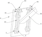
FIG. 3 is a schematic structural view of a limiting structure of the present application;
fig. 4 is a partial structural view of the reinforcing plate of the present application.
Illustration of the drawings: 1. a column; 2. a cross beam; 3. a reinforcing plate; 4. an expansion bolt; 5. a nut; 6. a support plate; 7. a limiting structure; 71. a limiting frame; 72. a connecting plate; 73. positioning blocks; 74. a bolt; 75. pulling a plate; 76. a spring; 77. a screw; 78. a rope; 79. a ball; 8. an auxiliary structure; 81. a square plate; 82. a concave plate; 83. a round bar; 84. pressing a plate; 85. a strip plate; 86. and (4) a groove.
Detailed Description
Referring to fig. 1 and 2, the present application provides a technical solution: the utility model provides a floor beam reinforced structure, including two stands 1 and crossbeam 2, one side that two stands 1 are close to each other all with crossbeam 2 fixed connection, two stand 1's surface mounting has four expansion bolts 4, expansion bolts 4's arc surface threaded connection has nut 5, gusset plate 3 is all installed on stand 1 and crossbeam 2's surface, two gusset plate 3's fixed surface is connected with backup pad 6, 3 sliding sleeve of gusset plate are at expansion bolts 4's arc surface, gusset plate 3 and 5 sliding connection of nut, stand 1's surface is equipped with limit structure 7, through setting up limit structure 7, reach when erection bracing board 6, carry out interim restriction to the position of backup pad 6, thereby make things convenient for the staff to carry out the effect of installation operation. Reinforcing plate 3 is equipped with two auxiliary structure 8 for the position of four nuts 5, through setting up auxiliary structure 8, reaches the position to nut 5 and restricts to avoid nut 5 to remove to the greatest extent and lead to the not hard up condition of reinforcing plate 3 to take place, and then improved the effect of structural practicality.
The specific arrangement and function of the limit structures 7 and the auxiliary structures 8 will be described in detail below.
Referring to fig. 3, in the present embodiment: the limiting structure 7 comprises a limiting frame 71, the limiting frame 71 is fixedly connected with the upright post 1, the inner wall of the limiting frame 71 is connected with two connecting plates 72 in a sliding mode, and the cross section of each connecting plate 72 is L-shaped. The horizontal screw thread on the surface of the long arm of connecting plate 72 is inserted with screw 77, screw 77 supports the surface of supporting plate 6, and the position of limiting frame 71 relative to two connecting plates 72 is all slided and penetrated with bolt 74. The surface of the short arm of the connecting plate 72 is provided with a jack, and the size of the jack on the connecting plate 72 is matched with the size of the bolt 74. Two bolts 74 keep away from stand 1's one end fixedly connected with arm-tie 75, and the fixed surface of the short arm of connecting plate 72 is connected with two locating pieces 73, and arm-tie 75 reaches the effect of two bolts 74 of convenient simultaneous pulling, and after locating piece 73 contacted with spacing frame 71, locating piece 73 reached and prevented connecting plate 72 from continuing to slide to make the effect that bolt 74 and jack align. One side of the pulling plate 75 close to the limiting frame 71 is fixedly connected with a spring 76, one end of the spring 76 far away from the pulling plate 75 is fixedly connected with the limiting frame 71, when the spring 76 contracts, the pulling plate 75 can slide towards the direction close to the limiting frame 71 by virtue of the pulling force of the spring 76, and the spring 76 achieves the effect of resetting the pulling plate 75. One side fixedly connected with rope 78 that arm-tie 75 kept away from spring 76, the one end fixedly connected with ball 79 that arm-tie 75 was kept away from to rope 78, and when pulling ball 79, rope 78 can drive arm-tie 75 with the help of ball 79 removes and slide, and rope 78 reaches the effect of conveniently pulling arm-tie 75.
Referring to fig. 4, specifically, the auxiliary structure 8 includes a square plate 81, the square plate 81 is fixedly connected with the reinforcing plate 3, two strip-shaped plates 85 vertically slide on the surface of the square plate 81, the nut 5 is located between the strip-shaped plates 85 and the reinforcing plate 3, the nut 5 is slidably connected with the strip-shaped plates 85, and the concave plates 82 are fixedly connected with the upper surfaces of the two strip-shaped plates 85. The surface of notch plate 82 is seted up flutedly 86, and the inner wall of notch plate 82 upper groove 86 rotates and is connected with round bar 83, and the arc surface fixedly connected with clamp plate 84 of round bar 83, the size of clamp plate 84 and notch plate 82 upper groove 86 size looks adaptation, and after clamp plate 84 and recess 86 dislocation, clamp plate 84 reaches the effect that restricts notch plate 82 position and then restriction strip 85 position.
The working principle is that when the limiting structure 7 needs to be used, the round ball 79 is pulled in the direction away from the limiting plate, the round ball 79 can pull the rope 78 to slide when sliding, the rope 78 can drive the pulling plate 75 to slide, the pulling plate 75 can pull the two bolts 74 to slide simultaneously when sliding, the pulling plate 75 achieves the effect of conveniently pulling the two bolts 74 simultaneously, when the bolts 74 slide to a proper position, the short arm of the connecting plate 72 slides in along the inner wall of the limiting frame 71, the connecting plate 72 slides to drive the positioning block 73 to slide, when the positioning block 73 is in contact with the limiting frame 71, the positioning block 73 achieves the effect of preventing the connecting plate 72 from continuing to slide, so that the jack is aligned with the bolts 74, then the round ball 79 is loosened, at the moment, the spring 76 begins to contract, the pulling plate 75 can slide in the direction close to the limiting frame 71 with the help of the pulling force of the spring 76, the pulling plate 75 can drive the bolts 74 to slide, when the bolts 74 are inserted into the inner wall of the jacks, the bolts 74 achieve the effect of limiting the position of the connecting plate 72, then the support plate 6 is placed between the two screws 77, and then the support plate 6 can be supported by a worker conveniently installing the screw 77.
When needs use auxiliary structure 8, the downward concave plate 82 that slides along the surface of square plate 81, concave plate 82 slides and can drive two bar shaped plate 85 and slide, slide to nut 5 when bar shaped plate 85 and keep away from one side of stand 1 after, bar shaped plate 85 reaches restriction nut 5 position, avoid nut 5 to produce the displacement and lead to the not hard up condition of gusset plate 3 to take place as far as possible, concave plate 82 slides the inner wall that can make recess 86 and slides along the arc surface of round bar 83, rotate round bar 83 after concave plate 82 and square plate 81 contact, round bar 83 rotates and can drive clamp plate 84 and rotate, after clamp plate 84 misplaces with recess 86, clamp plate 84 reaches restriction concave plate 82 position and then restricts the effect of bar shaped plate 85 position.
In the description of the present invention, it is to be noted that, unless otherwise explicitly specified or limited, the terms "mounted," "connected," and "connected" are to be construed broadly, and may be, for example, fixedly connected, detachably connected, or integrally connected; can be mechanically or electrically connected; they may be connected directly or indirectly through intervening media, or they may be interconnected between two elements. The specific meaning of the above terms in the present invention can be understood by those of ordinary skill in the art through specific situations.
Claims (6)
1. The utility model provides a floor beam reinforced structure, includes two stands (1) and crossbeam (2), its characterized in that: one sides of the two upright posts (1) close to each other are fixedly connected with the cross beam (2), four expansion bolts (4) are arranged on the surfaces of the two upright posts (1), the circular arc surface of the expansion bolt (4) is connected with a nut (5) through threads, reinforcing plates (3) are respectively arranged on the surfaces of the upright posts (1) and the cross beams (2), supporting plates (6) are fixedly connected with the surfaces of the two reinforcing plates (3), the reinforcing plate (3) is sleeved on the arc surface of the expansion bolt (4) in a sliding manner, the reinforcing plate (3) is connected with the nut (5) in a sliding way, the surface of the upright post (1) is provided with a limit structure (7), the limiting structure (7) comprises a limiting frame (71), the limiting frame (71) is fixedly connected with the upright post (1), the inner wall of the limit frame (71) is connected with two connecting plates (72) in a sliding way, the cross section of the connecting plate (72) is L-shaped, a screw rod (77) is inserted into the horizontal thread on the surface of the long arm of the connecting plate (72), the screw rod (77) is propped against the surface of the support plate (6), the positions of the limiting frame (71) relative to the two connecting plates (72) are provided with bolts (74) in a sliding and penetrating way, the surface of the short arm of the connecting plate (72) is provided with a jack, and the size of the jack on the connecting plate (72) is matched with that of the plug pin (74).
2. A floor beam reinforcing arrangement according to claim 1, characterized in that: two one end fixedly connected with arm-tie (75) that stand (1) was kept away from in bolt (74), the fixed surface of connecting plate (72) short arm is connected with two locating pieces (73).
3. A floor beam reinforcing structure according to claim 2, wherein: one side of the pulling plate (75) close to the limiting frame (71) is fixedly connected with a spring (76), and one end, far away from the pulling plate (75), of the spring (76) is fixedly connected with the limiting frame (71).
4. A floor beam reinforcing structure according to claim 2, wherein: one side of the pulling plate (75) far away from the spring (76) is fixedly connected with a rope (78), and one end of the rope (78) far away from the pulling plate (75) is fixedly connected with a round ball (79).
5. A floor beam reinforcing structure according to claim 1, wherein: reinforcing plate (3) are equipped with two auxiliary structure (8) for the position of four nuts (5), auxiliary structure (8) are including square plate (81), square plate (81) and reinforcing plate (3) fixed connection, the vertical slip in surface of square plate (81) runs through there are two bar boards (85), nut (5) are located between bar board (85) and reinforcing plate (3), nut (5) and bar board (85) sliding connection, two the last fixed surface of bar board (85) is connected with notch plate (82).
6. A floor beam reinforcing structure according to claim 5, wherein: the surface of the concave plate (82) is provided with a groove (86), the inner wall of the groove (86) on the concave plate (82) is rotatably connected with a round rod (83), the arc surface of the round rod (83) is fixedly connected with a pressing plate (84), and the size of the pressing plate (84) is matched with that of the groove (86) on the concave plate (82).
Priority Applications (1)
| Application Number | Priority Date | Filing Date | Title |
|---|---|---|---|
| CN202221894464.8U CN217999059U (en) | 2022-07-21 | 2022-07-21 | Floor beam reinforcing structure |
Applications Claiming Priority (1)
| Application Number | Priority Date | Filing Date | Title |
|---|---|---|---|
| CN202221894464.8U CN217999059U (en) | 2022-07-21 | 2022-07-21 | Floor beam reinforcing structure |
Publications (1)
| Publication Number | Publication Date |
|---|---|
| CN217999059U true CN217999059U (en) | 2022-12-09 |
Family
ID=84317137
Family Applications (1)
| Application Number | Title | Priority Date | Filing Date |
|---|---|---|---|
| CN202221894464.8U Expired - Fee Related CN217999059U (en) | 2022-07-21 | 2022-07-21 | Floor beam reinforcing structure |
Country Status (1)
| Country | Link |
|---|---|
| CN (1) | CN217999059U (en) |
-
2022
- 2022-07-21 CN CN202221894464.8U patent/CN217999059U/en not_active Expired - Fee Related
Similar Documents
| Publication | Publication Date | Title |
|---|---|---|
| CN217999059U (en) | Floor beam reinforcing structure | |
| CN213710356U (en) | Steel pipe scaffold for supporting wood formwork with strong installation stability | |
| CN217558282U (en) | Mounting base of sucker rod power tongs | |
| CN111424899A (en) | Steel construction building stair fixed point installation support device | |
| CN218346794U (en) | Aluminum alloy template for external wall insulation | |
| CN116104193A (en) | Assembled steel structure building | |
| CN213731545U (en) | Automatic assembling equipment for assembly type building connecting piece | |
| CN211371499U (en) | Metal pipeline support for steel structure engineering construction | |
| CN112854746A (en) | Inverted hanging type supporting system for steel truss floor support plate and construction method | |
| CN112252202A (en) | Hanging basket for bridge building | |
| CN215564694U (en) | Reinforcing device for engineering structure | |
| CN219280926U (en) | Connecting piece for steel structure combination | |
| CN217812407U (en) | Overlength concrete wall shrinkage crack control structure | |
| CN220365322U (en) | Pre-buried anchor bar construction equipment suitable for construction | |
| CN212743422U (en) | Supplementary splicing apparatus convenient to building steel structure installation | |
| CN219603046U (en) | Hoisting tool | |
| CN220644830U (en) | Telescopic suspender for installing light steel joist suspended ceiling | |
| CN210658909U (en) | Office building steel construction suspended ceiling conversion layer | |
| CN217054463U (en) | Connecting structure for reinforcing building beam | |
| CN212929288U (en) | Zinc liquid pump mounting rack | |
| CN217053500U (en) | Bridge steel pipe pile bearing capacity test structure | |
| CN214696977U (en) | Mounting and positioning fixing frame for primary and secondary beams of steel structure frame | |
| CN221422236U (en) | Steel structure connecting piece | |
| CN218562994U (en) | Cable tower reinforcing steel bar construction platform | |
| CN218149750U (en) | Full hall frame is with adjusting bracing piece |
Legal Events
| Date | Code | Title | Description |
|---|---|---|---|
| GR01 | Patent grant | ||
| GR01 | Patent grant | ||
| CF01 | Termination of patent right due to non-payment of annual fee | ||
| CF01 | Termination of patent right due to non-payment of annual fee |
Granted publication date: 20221209 |