CN217988570U - Water source treatment device with filter capable of backwashing - Google Patents
Water source treatment device with filter capable of backwashing Download PDFInfo
- Publication number
- CN217988570U CN217988570U CN202221529420.5U CN202221529420U CN217988570U CN 217988570 U CN217988570 U CN 217988570U CN 202221529420 U CN202221529420 U CN 202221529420U CN 217988570 U CN217988570 U CN 217988570U
- Authority
- CN
- China
- Prior art keywords
- wall
- pipe
- filter
- water source
- casing
- Prior art date
- Legal status (The legal status is an assumption and is not a legal conclusion. Google has not performed a legal analysis and makes no representation as to the accuracy of the status listed.)
- Active
Links
Images


Landscapes
- Filtration Of Liquid (AREA)
Abstract
The utility model discloses a but water source processing apparatus of filter back flush, including closing cap, casing and blow off pipe, the casing is installed through the bolt in the bottom of closing cap, the blow off pipe is installed to the bottom of casing, the motor is installed at the top of closing cap, the dwang is installed to the output of motor, the mid-mounting of dwang outer wall has waterproof the pad, and the bottom in the closing cap is installed at the top of waterproof pad. The utility model discloses a setting of solid fixed cylinder, annular mounting groove, annular mounting panel and filter tube, rivers pass through the inlet tube and flow into in the casing, and the filter tube plays the effect of filtering aquatic impurity, nevertheless through long-term the use, and the filtration pore on the filter tube blocks up easily there is impurity, and the motor drives the dwang rotatory, and the dwang drives the connecting rod rotatory, and the connecting rod drives the brush rotation, and the brush rotation can be with those impurity clearance down of card on the filter tube.
Description
Technical Field
The utility model relates to the technical field of filter equipment, in particular to a water source treatment device with a filter capable of back flushing.
Background
The filter is an indispensable device on a medium conveying pipeline and is usually arranged at the inlet end of a pressure reducing valve, a pressure relief valve, a constant water level valve and other equipment of a squaring filter. After the filter is provided with a filter cylinder with a filter screen with a certain specification, impurities are blocked, and after the impurities are blocked, the impurities are accumulated for a long time in the conventional filter equipment, so that the problems that the filter element is blocked, the water quality is poor and the like are easily caused.
The water source treatment device with a filter capable of backwashing in the prior art has the following defects:
patent document CN211097838U discloses a backwash filter, "comprising a housing, an electric mechanism, a filtering mechanism and a sewage draining mechanism; the electric mechanism is arranged on the outer side of the shell, the filtering mechanism is arranged in a cavity in the shell, and the sewage draining mechanism is connected to one side of the filtering mechanism; the filtering mechanism comprises a coarse filtering chamber, a fine filtering chamber and a water purifying chamber, wherein the coarse filtering chamber and the fine filtering chamber are separated by a flow control plate, and the fine filtering chamber and the water purifying chamber are separated by a fine filtering plate; the shell is provided with a water inlet communicated with the coarse filter chamber, a sewage outlet communicated with the fine filter chamber and a water outlet communicated with the purified water chamber, and the electric mechanism is connected with the flow control plate; the pneumatic cylinder of blowdown mechanism on one side of locating the water purification room and the briquetting of being connected with the pneumatic cylinder towards the water purification room side, this utility model, water reverse pressure in with the water purification room through blowdown mechanism makes the dirt on the fine filter plate discharge along with rivers, walks more dirt through a small amount of hosepipe ", but above-mentioned device when using, just is difficult to the clean up to the impurity of card on the filter.
SUMMERY OF THE UTILITY MODEL
An object of the utility model is to provide a water source processing apparatus that filter can be washed back to propose in solving above-mentioned background art just being difficult to the clean up problem to the impurity of card on the filter.
In order to achieve the purpose, the utility model provides the following technical scheme, the water source treatment device with the filter capable of back flushing comprises a sealing cover, a shell and a blow-off pipe, wherein the shell is arranged at the bottom of the sealing cover through a bolt, and the blow-off pipe is arranged at the bottom of the shell;
a motor is installed at the top of the sealing cover, and a rotating rod is installed at the output end of the motor;
the mid-mounting of dwang outer wall has waterproof pad, and the bottom in the closing cap is installed at the top of waterproof pad.
Preferably, the inlet tube is installed to the one end of casing outer wall, and the outlet pipe is installed to the other end of casing outer wall, and sealed cushion is installed to the inner wall of casing.
Preferably, the bottom of the blow-off pipe is provided with a blow-off valve, and the inner wall of the blow-off valve is provided with a hollow ball core.
Preferably, the bottom of the sealing cover is provided with a fixed cylinder, the outer wall of the fixed cylinder is provided with a drain pipe, and the outer wall of the drain pipe is arranged on the inner wall of the water outlet pipe.
Preferably, the bottom of the fixed cylinder is provided with an annular mounting groove, the inner wall of the annular mounting groove is provided with an annular mounting plate, and the bottom of the annular mounting plate is provided with a filter pipe.
Preferably, a plurality of connecting rod is installed to the outer wall of dwang, and the brush is installed to the one end of connecting rod.
Preferably, the valve rod is installed on the outer wall of the hollow ball core, and the nut is installed at the other end of the valve rod.
Compared with the prior art, the beneficial effects of the utility model are as follows:
1. the utility model discloses a setting of solid fixed cylinder, annular mounting groove, annular mounting panel and filter tube, rivers pass through the inlet tube and flow into in the casing, and the filter tube plays the effect of filtering aquatic impurity, nevertheless through long-term the use, and the filtration pore on the filter tube blocks up easily there is impurity, and the motor drives the dwang rotatory, and the dwang drives the connecting rod rotatory, and the connecting rod drives the brush rotation, and the brush rotation can be with those impurity clearance down of card on the filter tube.
2. The utility model discloses a setting of solid fixed cylinder and drain pipe, install the drain pipe in the inside of outlet pipe, the setting of the sealed cushion of rethread, make in close contact with between solid fixed cylinder and the sealed cushion, reach the effect of leak protection water, make rivers must pass through just can follow the outlet pipe outflow behind the chimney filter, avoid the rivers that contain impurity to get into the outlet pipe in, the swivel nut drives the valve rod and rotates, the valve rod rotates and drives hollow ball core and rotate and open the blowoff valve, through the setting of rivers and brush, so that pass through the blow off pipe with impurity and discharge.
Drawings
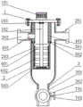
FIG. 1 is a perspective view of the overall structure of the present invention;
FIG. 2 is a schematic view of the housing structure of the present invention;
FIG. 3 is a schematic view of the structure of the filtering pipe of the present invention;
fig. 4 is a schematic diagram of the hollow ball core structure of the present invention.
In the figure: 1. sealing the cover; 2. a housing; 3. a blow-off pipe; 101. a motor; 102. rotating the rod; 103. a waterproof pad; 201. a water inlet pipe; 202. a water outlet pipe; 203. sealing the soft cushion; 301. a blowoff valve; 302. a hollow ball core; 401. a fixed cylinder; 402. a drain pipe; 501. an annular mounting groove; 502. an annular mounting plate; 503. a filter tube; 601. a connecting rod; 602. a brush; 701. a valve stem; 702. and a nut.
Detailed Description
The technical solutions in the embodiments of the present invention will be described clearly and completely with reference to the drawings in the embodiments of the present invention, and it is obvious that the described embodiments are only some embodiments of the present invention, not all embodiments. Based on the embodiments in the present invention, all other embodiments obtained by a person skilled in the art without creative work belong to the protection scope of the present invention.
In the description of the present invention, it should be noted that the terms "upper", "lower", "inner", "outer", "front end", "rear end", "both ends", "one end", "the other end" and the like indicate orientations or positional relationships based on the orientations or positional relationships shown in the drawings, and are only for convenience of description and simplification of description, but do not indicate or imply that the device or element to which the reference is made must have a specific orientation, be constructed in a specific orientation, and be operated, and thus, should not be construed as limiting the present invention. Furthermore, the terms "first," "second," and the like are used for descriptive purposes only and are not to be construed as indicating or implying relative importance.
In the description of the present invention, it is to be noted that, unless otherwise explicitly specified or limited, the terms "mounted," "disposed," "connected," and the like are to be construed broadly, and for example, "connected" may be either fixedly connected or detachably connected, or integrally connected; can be mechanically or electrically connected; they may be connected directly or indirectly through intervening media, or they may be interconnected between two elements. The specific meaning of the above terms in the present invention can be understood in specific cases to those skilled in the art.
Referring to fig. 1 and 2, in an embodiment of the present invention, a water source treatment device with a filter capable of backwashing includes a sealing cover 1, a housing 2 and a drain pipe 3, the housing 2 is installed at the bottom of the sealing cover 1 through a bolt, the drain pipe 3 is installed at the bottom of the housing 2, a water inlet pipe 201 is installed at one end of the outer wall of the housing 2, a water outlet pipe 202 is installed at the other end of the outer wall of the housing 2, and a sealing cushion 203 is installed on the inner wall of the housing 2;
referring to fig. 1, fig. 2 and fig. 3, a motor 101 is installed at the top of a sealing cover 1, a rotating rod 102 is installed at the output end of the motor 101, a waterproof pad 103 is installed at the middle of the outer wall of the rotating rod 102, the top of the waterproof pad 103 is installed at the bottom of the sealing cover 1, an annular installation groove 501 is formed in the bottom of a fixed cylinder 401, an annular installation plate 502 is installed on the inner wall of the annular installation groove 501, a filter pipe 503 is installed at the bottom of the annular installation plate 502, a plurality of connecting rods 601 are installed on the outer wall of the rotating rod 102, a brush 602 is installed at one end of each connecting rod 601, through the arrangement of the fixed cylinder 401, the annular installation groove 501, the annular installation plate 502 and the filter pipe 503, water flows into a housing 2 through a water inlet pipe 201, the filter pipe 503 plays a role in filtering impurities in water, but after long-term use, the filter holes in the filter pipe 503 are easily blocked with impurities, the motor 101 drives the rotating rod 102 to rotate, the rotating rod 102 drives the connecting rod 601 to rotate, the brush 602 to rotate, and the impurities blocked on the filter pipe 503 can be cleaned down by the brush 602.
Referring to fig. 1, 2 and 4, a blowoff valve 301 is installed at the bottom of a blowoff pipe 3, a hollow ball core 302 is installed on the inner wall of the blowoff valve 301, a fixed cylinder 401 is installed at the bottom of a sealing cover 1, a drain pipe 402 is installed on the outer wall of the fixed cylinder 401, the outer wall of the drain pipe 402 is installed on the inner wall of a water outlet pipe 202, a valve stem 701 is installed on the outer wall of the hollow ball core 302, a nut 702 is installed at the other end of the valve stem 701, the drain pipe 402 is installed inside the water outlet pipe 202 through the arrangement of the fixed cylinder 401 and the drain pipe 402, the fixed cylinder 401 is in close contact with the sealing cushion 203 through the arrangement of the sealing cushion 203, a water leakage prevention effect is achieved, water can flow out of the water outlet pipe 202 only after passing through the filter pipe 503, the water flow containing impurities is prevented from entering the water outlet pipe 202, the valve stem 701 is driven to rotate by the rotation of the nut 702, the hollow ball core 302 is driven by the rotation of the valve stem 701 to open the blowoff valve 301, and impurities are discharged through the arrangement of the water flow and the brush 602, so that the impurities are discharged through the blowoff pipe 3.
The working principle is that through the arrangement of the fixed cylinder 401, the annular mounting groove 501, the annular mounting plate 502 and the filter pipe 503, water flows into the shell 2 through the water inlet pipe 201, the filter pipe 503 has the effect of filtering impurities in water, but after long-term use, the filter hole on the filter pipe 503 is easily blocked with impurities, the motor 101 drives the rotating rod 102 to rotate, the rotating rod 102 drives the connecting rod 601 to rotate, the connecting rod 601 drives the brush 602 to rotate, the brush 602 rotates to clean the impurities clamped on the filter pipe 503 down, through the arrangement of the fixed cylinder 401 and the drain pipe 402, the drain pipe 402 is arranged inside the water outlet pipe 202, through the arrangement of the sealed cushion 203, the fixed cylinder 401 is in close contact with the sealed cushion 203, the effect of preventing water leakage is achieved, the water can flow out of the water outlet pipe 202 only after passing through the filter pipe 503, the water flow containing impurities is prevented from entering the water outlet pipe 202, the rotating nut 702 drives the valve rod 701 to rotate, the valve rod 701 rotates to drive the hollow ball core 302 to rotate to open the blow-off valve 301, through the arrangement of the water flow and the brush 602, so that the impurities are discharged through the blow-off pipe 3.
It will be evident to those skilled in the art that the invention is not limited to the details of the foregoing illustrative embodiments, and that the present invention may be embodied in other specific forms without departing from the spirit or essential attributes thereof. The present embodiments are therefore to be considered in all respects as illustrative and not restrictive, the scope of the invention being indicated by the appended claims rather than by the foregoing description, and all changes which come within the meaning and range of equivalency of the claims are therefore intended to be embraced therein. Any reference sign in a claim should not be construed as limiting the claim concerned.
Claims (7)
1. The utility model provides a but water source processing apparatus of filter back flush, includes closing cap (1), casing (2) and blow off pipe (3), its characterized in that: the bottom of the sealing cover (1) is provided with a shell (2) through a bolt, and the bottom of the shell (2) is provided with a sewage discharge pipe (3);
a motor (101) is installed at the top of the sealing cover (1), and a rotating rod (102) is installed at the output end of the motor (101);
the middle of the outer wall of the rotating rod (102) is provided with a waterproof pad (103), and the top of the waterproof pad (103) is arranged at the bottom of the sealing cover (1).
2. The apparatus of claim 1, wherein the water source treatment apparatus comprises: the water inlet pipe (201) is installed to the one end of casing (2) outer wall, and outlet pipe (202) is installed to the other end of casing (2) outer wall, and sealed cushion (203) are installed to the inner wall of casing (2).
3. The apparatus of claim 1, wherein the water source treatment apparatus comprises: a blow-down valve (301) is installed at the bottom of the blow-down pipe (3), and a hollow ball core (302) is installed on the inner wall of the blow-down valve (301).
4. The apparatus of claim 1, wherein the water source treatment apparatus comprises: a fixed cylinder (401) is installed at the bottom of the sealing cover (1), a drain pipe (402) is installed on the outer wall of the fixed cylinder (401), and the outer wall of the drain pipe (402) is installed on the inner wall of the water outlet pipe (202).
5. The apparatus of claim 4, wherein the water source treatment apparatus comprises: annular mounting groove (501) have been seted up to the bottom of fixed section of thick bamboo (401), and annular mounting panel (502) are installed to the inner wall of annular mounting groove (501), and filter tube (503) are installed to the bottom of annular mounting panel (502).
6. The apparatus of claim 1, wherein the water source treatment apparatus comprises: a plurality of connecting rod (601) is installed to the outer wall of dwang (102), and brush (602) are installed to the one end of connecting rod (601).
7. A filter backflushable water source treatment apparatus as claimed in claim 3 wherein: the outer wall of the hollow ball core (302) is provided with a valve rod (701), and the other end of the valve rod (701) is provided with a nut (702).
Priority Applications (1)
| Application Number | Priority Date | Filing Date | Title |
|---|---|---|---|
| CN202221529420.5U CN217988570U (en) | 2022-06-16 | 2022-06-16 | Water source treatment device with filter capable of backwashing |
Applications Claiming Priority (1)
| Application Number | Priority Date | Filing Date | Title |
|---|---|---|---|
| CN202221529420.5U CN217988570U (en) | 2022-06-16 | 2022-06-16 | Water source treatment device with filter capable of backwashing |
Publications (1)
| Publication Number | Publication Date |
|---|---|
| CN217988570U true CN217988570U (en) | 2022-12-09 |
Family
ID=84300349
Family Applications (1)
| Application Number | Title | Priority Date | Filing Date |
|---|---|---|---|
| CN202221529420.5U Active CN217988570U (en) | 2022-06-16 | 2022-06-16 | Water source treatment device with filter capable of backwashing |
Country Status (1)
| Country | Link |
|---|---|
| CN (1) | CN217988570U (en) |
-
2022
- 2022-06-16 CN CN202221529420.5U patent/CN217988570U/en active Active
Similar Documents
| Publication | Publication Date | Title |
|---|---|---|
| CN112044144B (en) | Backflushing type water filter | |
| CN105477922A (en) | Pre-filter with function of automatically cleaning filter screen | |
| CN210674451U (en) | Intelligent backwashing prefilter | |
| CN217988570U (en) | Water source treatment device with filter capable of backwashing | |
| CN217662177U (en) | Full-automatic internal brush type filter | |
| CN216320305U (en) | Back flush filter | |
| CN215916609U (en) | Pre-filter with back-washing filter element replacement-free function | |
| CN211706122U (en) | Water filter of steam boiler | |
| CN211411178U (en) | Self-cleaning filter | |
| CN209809652U (en) | Fluid drive formula sewage purification filter | |
| CN211513700U (en) | Y-shaped filter convenient for cleaning filter cylinder | |
| CN113975873A (en) | Back flush filter | |
| CN211113889U (en) | Drainage anti-blocking structure for tap water treatment | |
| CN214809031U (en) | Sewage treatment is with having water filtering device that can dismantle function | |
| CN213332553U (en) | A anti-backflow device for rain, sewage treatment | |
| CN213555639U (en) | Electric drive back flush filter | |
| CN214130699U (en) | Swimming pool ejection type filtering sand cylinder | |
| CN205269193U (en) | Take leading filter of self -cleaning filter screen function | |
| CN213942371U (en) | Anti-blocking water filter for power station | |
| CN216358847U (en) | Sunken back flush back-spray washing decompression prefilter | |
| CN215195656U (en) | Backwashing filter device for pressure pipeline exhaust valve | |
| CN218347966U (en) | Filtering and sewage draining gate valve | |
| CN218248717U (en) | Quick filter | |
| CN218687002U (en) | Backwashing water purifier | |
| CN220589128U (en) | Back flush filter screen filter |
Legal Events
| Date | Code | Title | Description |
|---|---|---|---|
| GR01 | Patent grant | ||
| GR01 | Patent grant |