CN217978733U - Heat radiation structure of street lamp holder - Google Patents
Heat radiation structure of street lamp holder Download PDFInfo
- Publication number
- CN217978733U CN217978733U CN202121927653.6U CN202121927653U CN217978733U CN 217978733 U CN217978733 U CN 217978733U CN 202121927653 U CN202121927653 U CN 202121927653U CN 217978733 U CN217978733 U CN 217978733U
- Authority
- CN
- China
- Prior art keywords
- wall
- street lamp
- lampshade
- support column
- lamp shade
- Prior art date
- Legal status (The legal status is an assumption and is not a legal conclusion. Google has not performed a legal analysis and makes no representation as to the accuracy of the status listed.)
- Active
Links
Images


Landscapes
- Arrangement Of Elements, Cooling, Sealing, Or The Like Of Lighting Devices (AREA)
- Non-Portable Lighting Devices Or Systems Thereof (AREA)
Abstract
The utility model discloses a heat radiation structure of street lamp holder, which comprises a base, surface mounting has the support column on the base, the connecting rod is installed to support column outer wall one side, the lamp shade is installed to connecting rod one end, surface mounting has dog A on the lamp shade, surface mounting has the stop collar on the lamp shade, stop collar internally mounted has the reference column, the fixed plate is installed to the reference column other end, the fixed plate upper surface is provided with the circular port, circular port inner wall bottom all is provided with the screw hole with stop collar inner wall bottom, be connected through fixing bolt between the screw hole of circular port inner wall bottom and the screw hole of stop collar inner wall bottom, temperature sensor is installed to lamp shade inner wall one side. The utility model discloses a setting of a series of structures, the effectual radiating speed of street lamp that has improved keeps the street lamp to carry out work under suitable temperature simultaneously, has improved the life of street lamp.
Description
Technical Field
The utility model relates to a street lamp technical field specifically is a heat radiation structure of street lamp holder.
Background
Street lamps refer to lamps providing a road with an illumination function, and generally to lamps in a road illumination range in traffic illumination. Street lamps are widely used in various places requiring illumination. Road lighting is an important component of urban lighting, and with the environmental protection concept getting deeper and deeper, the quantity of the street lamps in China is 2800-3000 ten thousand, the quantity of the newly added street lamps is 15-20% in recent years, and about 300-600 ten thousand street lamps play a great role in facilitating the life of the masses, beautifying the city and building an outward modern city.
The existing street lamp holder has the defects that: the existing street lamp cap is of a closed structure, the lampshade covers the bulb, so that heat accumulated in the lampshade cannot be discharged quickly, a heat dissipation function is omitted, the street lamp is easy to use in an actual use process, heat is accumulated in the lampshade easily, the service life of the street lamp is shortened, the maintenance cost is increased, and the street lamp is inconvenient to use.
SUMMERY OF THE UTILITY MODEL
An object of the utility model is to provide a heat radiation structure of street lamp holder to solve the problem that proposes among the above-mentioned background art.
In order to achieve the above object, the utility model provides a following technical scheme: the utility model provides a heat radiation structure of street lamp holder, includes the base, surface mounting has the support column on the base, the connecting rod is installed to support column outer wall one side, the lamp shade is installed to connecting rod one end, surface mounting has dog A on the lamp shade, surface mounting has the stop collar on the lamp shade, stop collar internally mounted has the reference column, the fixed plate is installed to the reference column other end, the fixed plate upper surface is provided with the circular port, circular port inner wall bottom and stop collar inner wall bottom all are provided with the screw hole, pass through fixing bolt connection between the screw hole of circular port inner wall bottom and the screw hole of stop collar inner wall bottom, temperature sensor is installed to lamp shade inner wall one side, lamp shade internally mounted has LED lamp and fan, and the fan is located LED lamp top, the backup pad is installed to support column outer wall one side, surface mounting has the control box in the backup pad, control box internally mounted has the controller.
Preferably, the top of the inner wall of the lampshade is provided with a vent hole.
Preferably, the display screen and the controller panel are installed on the front end face of the control box, the display screen is located above the controller panel, and the control button is installed on the controller panel.
Preferably, the base is provided with a mounting hole.
Preferably, the upper surface of the support column is provided with a lightning rod, and one side of the outer wall of the fixing plate is provided with a stop dog B.
Compared with the prior art, the beneficial effects of the utility model are that: the utility model discloses a fixed plate, the lamp shade, dog A, dog B, the air vent, the fan, a weighing sensor and a temperature sensor, a controller, fixing bolt, the cooperation setting of stop collar and reference column, the fixed plate is connected with the reference column, thereby make the fixed plate conveniently assemble through reference column and stop collar, be connected through fixing bolt between the screw hole of circular port inner wall bottom and the screw hole of stop collar inner wall bottom, thereby make fixing bolt fix the position of fixed plate, the lamp shade is connected with dog A, the fixed plate is connected with dog B, thereby make the air circulate through the gap between dog A and the dog B, dog A and dog B can block the rainwater simultaneously, play waterproof effect, controller control temperature sensor starts, temperature sensor carries out real-time monitoring to the inside temperature of lamp shade, when the inside temperature of lamp shade is greater than the default, controller control fan works, the fan outwards discharges the inside high temperature of lamp shade through the air vent. The utility model discloses a setting of a series of structures, the effectual radiating speed of street lamp that has improved keeps the street lamp to carry out work under suitable temperature simultaneously, has improved the life of street lamp.
Drawings
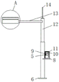
Fig. 1 is a schematic structural view of the present invention;
FIG. 2 is a front view of the present invention;
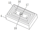
FIG. 3 is a schematic view of the structure of the lampshade of the present invention;
fig. 4 is a first schematic structural view of the fixing plate of the present invention;
fig. 5 is a schematic structural view of a fixing plate of the present invention;
fig. 6 is a cross-sectional view taken along line a of fig. 2 according to the present invention;
fig. 7 is a sectional view of the control box of the present invention.
In the figure: 1. fixing the bolt; 2. a circular hole; 3. a fixing plate; 4. a lamp shade; 5. a controller panel; 6. a base; 7. mounting holes; 8. a support plate; 9. a control button; 10. a display screen; 11. a control box; 12. a support pillar; 13. a connecting rod; 14. a lightning rod; 15. a block A; 16. a vent hole; 17. a limiting sleeve; 18. a threaded hole; 19. a positioning column; 20. a stop block B; 21. a temperature sensor; 22. an LED lamp; 23. a fan; 24. and a controller.
Detailed Description
The technical solutions in the embodiments of the present invention will be described clearly and completely with reference to the accompanying drawings in the embodiments of the present invention, and it is obvious that the described embodiments are only some embodiments of the present invention, not all embodiments. Based on the embodiments in the present invention, all other embodiments obtained by a person skilled in the art without creative efforts all belong to the protection scope of the present invention.
In the description of the present invention, it should be noted that the terms "upper", "lower", "inner", "outer", "front end", "rear end", "both ends", "one end", "the other end" and the like indicate orientations or positional relationships based on the orientations or positional relationships shown in the drawings, and are only for convenience of description and simplification of description, but do not indicate or imply that the device or element to which the reference is made must have a specific orientation, be constructed in a specific orientation, and be operated, and thus, should not be construed as limiting the present invention. Furthermore, the terms "first" and "second" are used for descriptive purposes only and are not to be construed as indicating or implying relative importance.
In the description of the present invention, it should be noted that, unless otherwise explicitly specified or limited, the terms "mounted," "provided," "connected," and the like are to be construed broadly, such as "connected," which may be fixedly connected, detachably connected, or integrally connected; can be mechanically or electrically connected; they may be connected directly or indirectly through intervening media, or they may be interconnected between two elements. The specific meaning of the above terms in the present invention can be understood in specific cases to those skilled in the art.
Referring to fig. 1-7, the present invention provides an embodiment: a heat dissipation structure of a street lamp cap comprises a base 6, a support post 12 is installed on the upper surface of the base 6, a connecting rod 13 is installed on one side of the outer wall of the support post 12, a lampshade 4 is installed at one end of the connecting rod 13, an air vent 16 is arranged at the top of the inner wall of the lampshade 4, a stop block A15 is installed on the upper surface of the lampshade 4, a limiting sleeve 17 is installed on the upper surface of the lampshade 4, a positioning column 19 is installed inside the limiting sleeve 17, a fixing plate 3 is installed at the other end of the positioning column 19, the fixing plate 3 is connected with the positioning column 19, so that the fixing plate 3 can be conveniently assembled with the limiting sleeve 17 through the positioning column 19, a circular hole 2 is formed in the upper surface of the fixing plate 3, threaded holes 18 are formed in the bottom of the inner wall of the circular hole 2 and the bottom of the inner wall of the limiting sleeve 17, the threaded hole 18 in the bottom of the inner wall of the circular hole 2 is connected with the threaded hole 18 in the bottom of the inner wall of the limiting sleeve 17 through a fixing bolt 1, the threaded hole 18 at the bottom of the inner wall of the circular hole 2 is connected with the threaded hole 18 at the bottom of the inner wall of the limiting sleeve 17 through the fixing bolt 1, so that the fixing bolt 1 fixes the position of the fixing plate 3, the temperature sensor 21 is installed on one side of the inner wall of the lampshade 4, the LED lamp 22 and the fan 23 are installed inside the lampshade 4, the fan 23 is positioned above the LED lamp 22, the lampshade 4 is connected with the stop A15, the fixing plate 3 is connected with the stop B20, so that air can circulate through a gap between the stop A15 and the stop B20, meanwhile, the stop A15 and the stop B20 can block rainwater, a waterproof effect is achieved, the controller 24 controls the temperature sensor 21 to be started, the temperature sensor 21 monitors the temperature inside the lampshade 4 in real time, when the temperature inside the lampshade 4 is greater than a preset value, the controller 24 controls the fan 23 to work, the fan 23 discharges the high temperature inside the lampshade 4 outwards through the vent hole 16, backup pad 8 is installed to support column 12 outer wall one side, surface mounting has control box 11 on the backup pad 8, 11 internally mounted of control box has controller 24, display screen 10 and controller panel 5 are installed to the terminal surface before 11 control boxes, and display screen 10 is located controller panel 5 top, install control button 9 on the controller panel 5, be provided with mounting hole 7 on the base 6, surface mounting has lightning rod 14 on the support column 12, dog B20 is installed to 3 outer wall one sides of fixed plate.
The working principle is as follows: during the use, install fixed plate 3 on lamp shade 4, switch on external power supply, fixed plate 3 is connected with reference column 19, thereby make fixed plate 3 conveniently assemble with stop collar 17 through reference column 19, be connected through fixing bolt 1 between the screw hole 18 of circular port 2 inner wall bottom and the screw hole 18 of stop collar 17 inner wall bottom, thereby make fixing bolt 1 fix the position of fixed plate 3, lamp shade 4 is connected with dog A15, fixed plate 3 is connected with dog B20, thereby make the air circulate through the gap between dog A15 and dog B20, dog A15 and dog B20 can block the rainwater simultaneously, play waterproof effect, controller 24 control temperature sensor 21 starts, temperature sensor 21 carries out real-time monitoring to the inside temperature of lamp shade 4, when the inside temperature of lamp shade 4 is greater than the default, controller 24 control fan 23 works, fan 23 outwards discharges the inside high temperature of lamp shade 4 through air vent 16.
It will be evident to those skilled in the art that the invention is not limited to the details of the foregoing illustrative embodiments, and that the present invention may be embodied in other specific forms without departing from the spirit or essential attributes thereof. The present embodiments are therefore to be considered in all respects as illustrative and not restrictive, the scope of the invention being indicated by the appended claims rather than by the foregoing description, and all changes which come within the meaning and range of equivalency of the claims are therefore intended to be embraced therein. Any reference sign in a claim should not be construed as limiting the claim concerned.
Claims (5)
1. The utility model provides a heat radiation structure of street lamp holder, includes base (6), its characterized in that: a support column (12) is arranged on the upper surface of the base (6), a connecting rod (13) is arranged on one side of the outer wall of the support column (12), a lampshade (4) is arranged at one end of the connecting rod (13), a stop block A (15) is arranged on the upper surface of the lampshade (4), the upper surface of the lampshade (4) is provided with a limit sleeve (17), a positioning column (19) is arranged in the limit sleeve (17), the other end of the positioning column (19) is provided with a fixing plate (3), the upper surface of the fixing plate (3) is provided with a circular hole (2), the bottom of the inner wall of the circular hole (2) and the bottom of the inner wall of the limiting sleeve (17) are both provided with threaded holes (18), the threaded hole (18) at the bottom of the inner wall of the circular hole (2) is connected with the threaded hole (18) at the bottom of the inner wall of the limiting sleeve (17) through a fixing bolt (1), a temperature sensor (21) is arranged on one side of the inner wall of the lampshade (4), the LED lamp (22) and the fan (23) are arranged in the lampshade (4), and the fan (23) is positioned above the LED lamp (22), one side of the outer wall of the support column (12) is provided with a support plate (8), the upper surface of the supporting plate (8) is provided with a control box (11), and a controller (24) is arranged in the control box (11).
2. The heat dissipation structure of a street lamp cap as set forth in claim 1, wherein: and a vent hole (16) is formed in the top of the inner wall of the lampshade (4).
3. The heat dissipation structure of a street lamp cap as set forth in claim 1, wherein: display screen (10) and controller panel (5) are installed to terminal surface before control box (11), and display screen (10) are located controller panel (5) top, install control button (9) on controller panel (5).
4. The heat dissipation structure of a street lamp cap as claimed in claim 1, wherein: the base (6) is provided with a mounting hole (7).
5. The heat dissipation structure of a street lamp cap as claimed in claim 1, wherein: the lightning rod (14) is installed to support column (12) upper surface, dog B (20) are installed to fixed plate (3) outer wall one side.
Priority Applications (1)
| Application Number | Priority Date | Filing Date | Title |
|---|---|---|---|
| CN202121927653.6U CN217978733U (en) | 2021-08-17 | 2021-08-17 | Heat radiation structure of street lamp holder |
Applications Claiming Priority (1)
| Application Number | Priority Date | Filing Date | Title |
|---|---|---|---|
| CN202121927653.6U CN217978733U (en) | 2021-08-17 | 2021-08-17 | Heat radiation structure of street lamp holder |
Publications (1)
| Publication Number | Publication Date |
|---|---|
| CN217978733U true CN217978733U (en) | 2022-12-06 |
Family
ID=84253548
Family Applications (1)
| Application Number | Title | Priority Date | Filing Date |
|---|---|---|---|
| CN202121927653.6U Active CN217978733U (en) | 2021-08-17 | 2021-08-17 | Heat radiation structure of street lamp holder |
Country Status (1)
| Country | Link |
|---|---|
| CN (1) | CN217978733U (en) |
-
2021
- 2021-08-17 CN CN202121927653.6U patent/CN217978733U/en active Active
Similar Documents
| Publication | Publication Date | Title |
|---|---|---|
| CN217978733U (en) | Heat radiation structure of street lamp holder | |
| CN201149228Y (en) | Street lamp | |
| CN215446246U (en) | A rain-proof water lighting fixture for building site | |
| CN210107155U (en) | Low-blue-light LED lighting device | |
| CN212273903U (en) | Multi-functional DIY lamp pole | |
| CN109026839B (en) | Detachable waterproof dust cover device | |
| CN210717319U (en) | Integrated solar street lamp | |
| CN214172121U (en) | LED street lamp with good heat dissipation effect | |
| CN218415366U (en) | Block terminal for building engineering | |
| CN215722977U (en) | Traffic intelligent energy-saving lamp | |
| CN205845423U (en) | A kind of display screen being arranged on Entertainment Plaza convenient maintenance | |
| CN218178729U (en) | A induction type ceiling lamp for parking area illumination | |
| CN210219580U (en) | Solar low-light-intensity aviation obstruction light | |
| CN211203876U (en) | Factory street lamp based on Internet of things | |
| CN204460053U (en) | Solar integration LED lamp | |
| CN211006434U (en) | Road indicating device for traffic engineering | |
| CN215636920U (en) | Special heat dissipation street lamp of brightening engineering | |
| CN213362282U (en) | LED street lamp | |
| CN213019226U (en) | Constant temperature LED lamp | |
| CN216619630U (en) | LED street lamp with high-efficient heat dispersion | |
| CN218153955U (en) | Lighting lamp with dustproof function | |
| CN219318263U (en) | Landscape lamp capable of sensing pedestrians | |
| CN217603982U (en) | LED street lamp capable of intelligently sensing temperature and dissipating heat | |
| CN212901220U (en) | Lighting device with heat dissipation function for building site | |
| CN217235456U (en) | LED wall washer lamp with waterproof function |
Legal Events
| Date | Code | Title | Description |
|---|---|---|---|
| GR01 | Patent grant | ||
| GR01 | Patent grant |