CN217965520U - Welding tool for machining inner supporting pipe assembly - Google Patents
Welding tool for machining inner supporting pipe assembly Download PDFInfo
- Publication number
- CN217965520U CN217965520U CN202220712475.3U CN202220712475U CN217965520U CN 217965520 U CN217965520 U CN 217965520U CN 202220712475 U CN202220712475 U CN 202220712475U CN 217965520 U CN217965520 U CN 217965520U
- Authority
- CN
- China
- Prior art keywords
- welding tool
- cylinder
- workstation
- plate
- lifter plate
- Prior art date
- Legal status (The legal status is an assumption and is not a legal conclusion. Google has not performed a legal analysis and makes no representation as to the accuracy of the status listed.)
- Active
Links
Images


Abstract
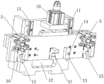
The utility model relates to a welding frock of vaulting pole subassembly in processing, comprises a workbench, the middle part support is installed to the workstation upper end, a tip support is respectively installed to the both sides that the workstation upper end is located the middle part support, the baffle is installed in the outside that the workstation upper end is located one of them tip support, the workstation upper end is located and installs two closing device side by side between two tip supports, the riser is installed to the rear that the workstation upper end is located the middle part support, gliding lift cylinder about lifter plate and drive lifter plate is installed to the riser front end, the mid-mounting of terminal surface has the supporting shoe before the lifter plate, the supporting shoe front end is equipped with the hole site arch, a U-shaped piece is respectively installed to the both sides that the terminal surface is located the supporting shoe before the lifter plate, a closing device is all installed in the outside that the terminal surface is located every U-shaped piece before the lifter plate. The utility model discloses to take the interior pipe that props of crossbeam and the interior pipe that props that does not take the crossbeam to carry out accurate location, be difficult to in the welding process take place to rock, can effectively reduce the welding degree of difficulty.
Description
Technical Field
The utility model relates to a lift table technical field especially relates to a welding frock of stay tube subassembly in processing.
Background
The height of a common table on the market can not be adjusted up and down, and can not meet the requirements of different heights; in order to achieve the purpose of lifting the table, lifting tables are available on the market, which generally comprise a base, a table top plate, a table frame, a lifting frame and the like, wherein an inner supporting pipe component is an important part of the lifting table.
As shown in fig. 4, the inner supporting pipe assembly comprises two inner supporting pipes 25 and a cross beam 22, a supporting leg 23 is welded in the middle of each inner supporting pipe 25, a circular through hole 28 for connection and installation is further formed in each inner supporting pipe 25, the cross beam 22 is welded on one inner supporting pipe 25, the free end of the cross beam 22 and the other inner supporting pipe 25 need to be accurately butted and then welded, shaking is not guaranteed in the welding process, a special welding tool is not provided at present, welding among all parts is not accurate enough, and the machining efficiency is low.
Disclosure of Invention
The utility model aims to solve the technical problem that a welding frock of vaulting pipe subassembly in processing is provided, will take the interior pipe that props of crossbeam and the interior pipe that props that does not take the crossbeam to carry out accurate location, be difficult to take place to rock in the welding process, can effectively reduce the welding degree of difficulty, improve machining efficiency simultaneously. The utility model discloses can also the range estimation take the interior stay pipe of crossbeam whether meet the requirements, it is met the requirements to guarantee the stabilizer blade position through the location detection round pin.
The utility model provides a technical scheme that its technical problem adopted is: the utility model provides a welding frock of vaulting pole subassembly in processing, comprises a workbench, workstation upper end install the middle part support, a tip support is respectively installed to the both sides that this workstation upper end is located the middle part support, workstation upper end be located the outside of one of them tip support and install the baffle, this workstation upper end is located and installs two closing device side by side between two tip supports, workstation upper end be located the rear of middle part support and install the riser, gliding lift cylinder about lifter plate and the drive lifter plate is installed to this riser front end, the mid-mounting of lifter plate front end face have the supporting shoe, the front end of supporting shoe and the upper end of middle part support all be equipped with a hole site arch, lifter plate front end face be located the both sides of supporting shoe and respectively install a U-shaped piece, a closing device is all installed in the outside that this lifter plate front end face is located every U-shaped piece.
It is right as technical scheme's a supplement, workstation upper end be located middle part support one side and install gliding fore-set from top to bottom, workstation bottom vertically install a jacking cylinder, the piston rod upper end of this jacking cylinder links to each other with the fore-set.
As right technical scheme a supplement, the riser front end arranged two vertical guide rails side by side, the lifter plate slide from top to bottom along two vertical guide rails.
As right technical scheme a supplement, riser front end middle part be located two vertical guide rails between seted up the rectangle fretwork.
As right technical scheme a supplement, lifter plate before the terminal surface be located and install an L shape benchmark piece between two U-shaped blocks.
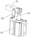
As right technical scheme a supplement, closing device including compressing tightly the cylinder, rotating seat and clamp plate, the piston rod that compresses tightly the cylinder on rotate and be connected with the clamp plate, should compress tightly and lie in piston rod one side on the cylinder and install and rotate the seat, the both sides of rotating the seat respectively rotate and install a connecting plate, two connecting plates rotate with clamp plate middle part both sides respectively and are connected.
As right technical scheme a supplement, lifter plate before the outside that the terminal surface is located one of them U-shaped piece install a curb plate.
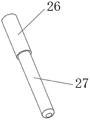
It is right as a supplement to technical scheme, still include the location and detect the round pin, the location detect the round pin and include axial connection's first cylinder and second cylinder, first cylindrical diameter be greater than the cylindrical diameter of second.
Has the advantages that: the utility model relates to a welding frock of stay tube subassembly in processing will take the interior stay pipe of crossbeam and the interior stay pipe that does not take the crossbeam to carry out accurate location, is difficult to take place to rock in the welding process, can effectively reduce the welding degree of difficulty, improves machining efficiency simultaneously. The utility model discloses can also the range estimation take the interior stay pipe of crossbeam whether meet the requirements, detect the round pin through the location and guarantee that the stabilizer blade position meets the requirements.
Drawings
Fig. 1 is a schematic structural diagram of the present invention;
fig. 2 is a schematic structural diagram of the vertical plate according to the present invention;
fig. 3 is a schematic structural view of the compressing device of the present invention;
fig. 4 is a schematic structural view of the inner supporting tube assembly of the present invention;
fig. 5 is a schematic structural view of the positioning detection pin of the present invention.
The figure is as follows: 1. the workstation, 2, the middle part support, 3, the jacking cylinder, 4, the fore-set, 5, closing device, 6, the baffle, 7, the tip support, 8, the lifter plate, 9, the riser, 10, the lifting cylinder, 11, vertical guide rail, 12, the rectangle fretwork, 13, the supporting shoe, 14, the hole site is protruding, 15, U-shaped piece, 16, the curb plate, 17, L shape reference block, 18, compress tightly the cylinder, 19, rotate the seat, 20, the connecting plate, 21, the clamp plate, 22, the crossbeam, 23, the stabilizer blade, 24, the location detects the round pin, 25, the interior pipe that props, 26, first cylinder, 27, the second cylinder, 28, circular through-hole.
Detailed Description
The present invention will be further described with reference to the following specific examples. It should be understood that these examples are for illustrative purposes only and are not intended to limit the scope of the present invention. Furthermore, it should be understood that various changes and modifications of the present invention may be made by those skilled in the art after reading the teachings of the present invention, and these equivalents also fall within the scope of the appended claims.
The utility model discloses an embodiment relates to a welding frock of processing interior vaulting pole subassembly, as shown in fig. 1-5, including workstation 1, workstation 1 upper end install middle part support 2, a tip support 7 is respectively installed to the both sides that this workstation 1 upper end lies in middle part support 2, workstation 1 upper end lie in the outside of one of them tip support 7 and install baffle 6, this workstation 1 upper end lies in and installs two closing devices 5 side by side between two tip supports 7, workstation 1 upper end lie in the rear of middle part support 2 and install riser 9, this riser 9 front end is installed lifter plate 8 and is driven lifter plate 8 gliding lift cylinder 10 from top to bottom, the mid-mounting of lifter plate 8 front end face have a supporting shoe 13, the front end of supporting shoe 13 and the upper end of middle part support 2 all be equipped with a hole site arch 14, lifter plate 8 front end face lie in the both sides of supporting shoe 13 and respectively install a U-shaped piece 15, lifter plate 8 front end face lie in the outside of every U-shaped piece 15 and all install a closing device 5, lifter plate 8 front end face lie in the outside of one of them and install a curb plate 16; the upper end of the end support 7 and the upper end of the middle support 2 are both provided with V-shaped openings, and the inner support tube 25 is limited through the V-shaped openings.
The upper end of the workbench 1 is positioned on one side of the middle support 2 and is provided with a top column 4 which slides up and down, the bottom of the workbench 1 is vertically provided with a jacking cylinder 3, and the upper end of a piston rod of the jacking cylinder 3 is connected with the top column 4.
Two vertical guide rails 11 are arranged at the front end of the vertical plate 9 side by side, the lifting plate 8 slides up and down along the two vertical guide rails 11, a rectangular hollow 12 is arranged between the two vertical guide rails 11 in the middle of the front end of the vertical plate 9, and the rectangular hollow 12 is arranged to effectively reduce the weight of the vertical plate 9.
An L-shaped reference block 17 is arranged between the two U-shaped blocks 15 on the front end face of the lifting plate 8, the L-shaped reference block 17 can calibrate the position of the cross beam 22, and an inner supporting pipe 25 with the cross beam 22 is visually inspected to determine whether the inner supporting pipe meets the requirement or not, if the cross beam 22 is aligned with the L-shaped reference block 17, the inner supporting pipe meets the requirement, otherwise, the inner supporting pipe does not meet the requirement.
Before welding, the inner supporting tube 25 without the cross beam 22 is placed on the two end supports 7 and the middle support 2, the circular through hole 28 in the inner supporting tube 25 is buckled with the hole site bulge 14 in the middle support 2, the left end of the inner supporting tube 25 leans against the baffle 6, the position of the first inner supporting tube 25 is limited, then the corresponding pressing device 5 is started to press the inner supporting tube 25, then the inner supporting tube 25 with the cross beam 22 is placed on the two U-shaped blocks 15 and the supporting block 13, the circular through hole 28 in the inner supporting tube 25 is buckled with the hole site bulge 14 in the supporting block 13, the left end of the inner supporting tube 25 leans against the side plate 16, the second inner supporting tube 25 is accurately positioned, then the corresponding pressing device 5 is started to press the inner supporting tube 25, then the lifting cylinder 10 is started, the lifting plate 8 moves downwards, the free end of the cross beam 22 is accurately butted with the inner supporting tube 25 below, the positioning detection pin 24 is inserted downwards, if the second cylinder 27 sequentially penetrates through the two supporting legs 23, the position between the supporting tube 23 and the inner supporting tube 25 is qualified, otherwise, the inner supporting tube 22 is welded with the lower end of the qualified cross beam. After the welding is finished, the pressing device 5 is loosened, and the jacking cylinder 3 is started to eject the welded workpiece out through the jacking column 4.
The pressing device 5 comprises a pressing cylinder 18, a rotating seat 19 and a pressing plate 21, the pressing plate 21 is rotatably connected to a piston rod of the pressing cylinder 18, the rotating seat 19 is mounted on one side of the piston rod of the pressing cylinder 18, two connecting plates 20 are rotatably mounted on two sides of the rotating seat 19 respectively, and the two connecting plates 20 are rotatably connected with two sides of the middle of the pressing plate 21 respectively; when the pressing is needed, the pressing cylinder 18 is started, and the piston rod of the pressing cylinder 18 extends to press the free end of the pressing plate 21 downwards.
The positioning detection pin 24 is further included, the positioning detection pin 24 comprises a first cylinder 26 and a second cylinder 27 which are axially connected, the diameter of the first cylinder 26 is larger than that of the second cylinder 27, the second cylinder 27 can penetrate through the hole of the support 23, and the first cylinder 26 cannot penetrate through the hole of the support 23.
In the description of the present invention, it should be understood that the orientation or positional relationship indicated by the orientation words such as "front, back, up, down, left, right", "horizontal, vertical, horizontal" and "top, bottom" etc. are usually based on the orientation or positional relationship shown in the drawings, and are only for convenience of description and simplification of description, and in the case of not making a contrary explanation, these orientation words do not indicate and imply that the device or element referred to must have a specific orientation or be constructed and operated in a specific orientation, and therefore, should not be interpreted as limiting the scope of the present invention; the terms "inner and outer" refer to the inner and outer relative to the profile of the respective component itself.
For ease of description, spatially relative terms such as "above … …", "above … …", "above … … upper surface", "above", etc. may be used herein to describe the spatial positional relationship of one device or feature to other devices or features as shown in the figures. It will be understood that the spatially relative terms are intended to encompass different orientations of the device in use or operation in addition to the orientation depicted in the figures. For example, if a device in the figures is turned over, devices described as "above" or "on" other devices or configurations would then be oriented "below" or "under" the other devices or configurations. Thus, the exemplary term "above … …" may include both orientations of "above … …" and "below … …". The device may be otherwise variously oriented (rotated 90 degrees or at other orientations) and the spatially relative descriptors used herein interpreted accordingly.
It should be noted that the terms "first", "second", and the like are used to define the components, and are only used for convenience of distinguishing the corresponding components, and the terms do not have special meanings unless otherwise stated, and therefore, the scope of the present invention should not be construed as being limited.
The welding tool for processing the inner support pipe assembly provided by the application is described in detail, and the principle and the implementation mode of the application are explained by applying the specific examples, and the description of the above embodiments is only used for helping to understand the method and the core idea of the application; meanwhile, for a person skilled in the art, according to the idea of the present application, the specific implementation manner and the application scope may be changed, and in summary, the content of the present specification should not be construed as a limitation to the present application.
Claims (8)
1. The utility model provides a welding frock of vaulting pole subassembly in processing, includes workstation (1), its characterized in that: workstation (1) upper end install middle part support (2), a tip support (7) is respectively installed to the both sides that this workstation (1) upper end is located middle part support (2), workstation (1) upper end be located the outside of one of them tip support (7) and install baffle (6), this workstation (1) upper end is located and installs two closing device (5) side by side between two tip supports (7), workstation (1) upper end be located the rear of middle part support (2) and install riser (9), riser (8) and drive lifter plate (8) gliding lift cylinder (10) from top to bottom are installed to this riser (9) front end, lifter plate (8) front end's mid-mounting have supporting shoe (13), the front end of supporting shoe (13) and the upper end of middle part support (2) all be equipped with one protruding (14), lifter plate (8) front end be located the both sides of supporting shoe (13) and respectively install a U-shaped piece (15), this lifter plate (8) front end is located the outside of every U-shaped piece (15) and all installs closing device (5).
2. The welding tool for machining the inner support pipe assembly according to claim 1, wherein the welding tool comprises: workstation (1) upper end be located middle part support (2) one side and install gliding fore-set (4) from top to bottom, workstation (1) bottom vertically install a jacking cylinder (3), the piston rod upper end of this jacking cylinder (3) links to each other with fore-set (4).
3. The welding tool for machining the inner support pipe assembly according to claim 1, wherein the welding tool comprises: two vertical guide rails (11) are arranged at the front end of the vertical plate (9) side by side, and the lifting plate (8) slides up and down along the two vertical guide rails (11).
4. The welding tool for machining the inner supporting pipe assembly according to claim 3, wherein the welding tool comprises: the middle part of the front end of the vertical plate (9) is positioned between the two vertical guide rails (11) and is provided with a rectangular hollow part (12).
5. The welding tool for machining the inner support pipe assembly according to claim 1, wherein the welding tool comprises: an L-shaped reference block (17) is arranged between the two U-shaped blocks (15) on the front end surface of the lifting plate (8).
6. The welding tool for machining the inner support pipe assembly according to claim 1, wherein the welding tool comprises: the pressing device (5) comprises a pressing cylinder (18), a rotating seat (19) and a pressing plate (21), the pressing cylinder (18) is connected with the pressing plate (21) in a rotating mode on a piston rod, the rotating seat (19) is installed on one side, located on one side of the piston rod, of the pressing cylinder (18), two connecting plates (20) are installed on two sides of the rotating seat (19) in a rotating mode, and the two connecting plates (20) are respectively connected with two sides of the middle of the pressing plate (21) in a rotating mode.
7. The welding tool for machining the inner support pipe assembly according to claim 1, wherein the welding tool comprises: a side plate (16) is arranged on the outer side of one U-shaped block (15) on the front end face of the lifting plate (8).
8. The welding tool for machining the inner support pipe assembly according to claim 1, wherein the welding tool comprises: the positioning detection device further comprises a positioning detection pin (24), wherein the positioning detection pin (24) comprises a first cylinder (26) and a second cylinder (27) which are axially connected, and the diameter of the first cylinder (26) is larger than that of the second cylinder (27).
Priority Applications (1)
| Application Number | Priority Date | Filing Date | Title |
|---|---|---|---|
| CN202220712475.3U CN217965520U (en) | 2022-03-30 | 2022-03-30 | Welding tool for machining inner supporting pipe assembly |
Applications Claiming Priority (1)
| Application Number | Priority Date | Filing Date | Title |
|---|---|---|---|
| CN202220712475.3U CN217965520U (en) | 2022-03-30 | 2022-03-30 | Welding tool for machining inner supporting pipe assembly |
Publications (1)
| Publication Number | Publication Date |
|---|---|
| CN217965520U true CN217965520U (en) | 2022-12-06 |
Family
ID=84254322
Family Applications (1)
| Application Number | Title | Priority Date | Filing Date |
|---|---|---|---|
| CN202220712475.3U Active CN217965520U (en) | 2022-03-30 | 2022-03-30 | Welding tool for machining inner supporting pipe assembly |
Country Status (1)
| Country | Link |
|---|---|
| CN (1) | CN217965520U (en) |
-
2022
- 2022-03-30 CN CN202220712475.3U patent/CN217965520U/en active Active
Similar Documents
| Publication | Publication Date | Title |
|---|---|---|
| CN104015033B (en) | Bulb press-loading device | |
| CN217965520U (en) | Welding tool for machining inner supporting pipe assembly | |
| CN217965519U (en) | Device for processing inner support pipe welding assembly | |
| CN214816133U (en) | A anchor clamps for processing lift table telescopic link welding piece | |
| CN214044281U (en) | High-layer-number ultra-thick circuit board multi-row connector through hole welding equipment | |
| CN217452736U (en) | Device for processing short beam welding assembly | |
| CN217452737U (en) | Welding tool for machining short legs of lifting table | |
| CN219900885U (en) | Welding fixture for ground hiding support arm of lifting machine | |
| CN219703959U (en) | Tool for machining basic welding piece of lifting table leg | |
| CN112846437A (en) | Device and process for welding multiple rows of connector through holes of high-layer-number super-thick circuit board | |
| CN212095047U (en) | Stay wire elastic tube welding jig | |
| CN208467643U (en) | A kind of high-precision elevator car frame plank welding tooling | |
| CN214816134U (en) | Tool for machining lifting table base welding assembly | |
| CN210908822U (en) | High pipe clamp equipment of security | |
| CN214868296U (en) | Tool for machining lifting table side crosspiece welding assembly | |
| CN220259988U (en) | Welding positioning tool for frame assembly | |
| CN217452738U (en) | Tool for machining lifting table beam welding assembly | |
| CN219391245U (en) | Die casting soaking type air tightness detection device | |
| CN220636834U (en) | Automobile threshold connection angle iron welding auxiliary device | |
| CN212384895U (en) | Seat welding carrier for realizing left and right frame positioning through connecting rod | |
| CN109926781A (en) | A kind of welding tooling | |
| CN211889638U (en) | Welding tool for vertical pressure tank seal head | |
| CN209936214U (en) | Bulldozer floor frame welding tool | |
| CN219542130U (en) | Frame assembly frock on excavator | |
| CN115846987A (en) | Frame group is to frock on excavator |
Legal Events
| Date | Code | Title | Description |
|---|---|---|---|
| GR01 | Patent grant | ||
| GR01 | Patent grant |