CN217925290U - Fender is enclosed in municipal works construction - Google Patents
Fender is enclosed in municipal works construction Download PDFInfo
- Publication number
- CN217925290U CN217925290U CN202221898109.8U CN202221898109U CN217925290U CN 217925290 U CN217925290 U CN 217925290U CN 202221898109 U CN202221898109 U CN 202221898109U CN 217925290 U CN217925290 U CN 217925290U
- Authority
- CN
- China
- Prior art keywords
- frame
- chassis
- fender
- wall
- concatenation
- Prior art date
- Legal status (The legal status is an assumption and is not a legal conclusion. Google has not performed a legal analysis and makes no representation as to the accuracy of the status listed.)
- Active
Links
Images


Landscapes
- Refuge Islands, Traffic Blockers, Or Guard Fence (AREA)
Abstract
The utility model relates to the technical field of municipal works, and discloses a municipal engineering construction enclosure, which comprises an underframe, a splicing frame and frame grooves, wherein the bottom surface of the splicing frame is contacted with the upper surface of the underframe, the inside of each frame groove is clamped with the outer surface of the underframe, the inner top wall of each frame groove is fixedly provided with a connecting rod, the upper surface of the underframe is provided with three jacks, the upper surface of the underframe is provided with a plurality of same fixed grooves, the inside of each fixed groove is clamped with a support plate, the outer surface of each support plate is slidably connected with a sleeve plate, and the inner wall of each sleeve plate is rotatably connected with a rotating shaft; the utility model discloses a be provided with chassis, concatenation frame, frame groove, connecting rod and jack, all install on concatenation frame and the chassis and enclose the fender to can utilize the concatenation frame to increase and enclose the effect of fender height, realize that the concatenation increases and encloses the purpose that keeps off the height and then conveniently change, enclose the problem that the fender height leads to changing the unidimensional fender in order to avoid inconvenient increase.
Description
Technical Field
The utility model relates to a municipal works technical field specifically is a fender is enclosed in municipal works construction.
Background
The municipal infrastructure refers to various buildings, structures, equipment and the like which are arranged in the planning and construction range of urban areas and towns and provide paid or unpaid public products and services for residents based on government responsibilities and obligations, and various public infrastructure constructions matched with urban life belong to the municipal engineering category.
The utility model discloses a fender is enclosed in municipal works construction to current grant notice number CN216277289U, including enclosing fender body and connection structure, connection structure sets up and is enclosing fender body surface, encloses the fender body and includes the base, and fixed surface has the stand on the base, and the spout has all been seted up to the stand left and right sides, and the inside slip of spout is provided with the slide.
Adopt above-mentioned technical scheme, although be used for the guard action in the municipal works work progress through enclosing the fender body, made things convenient for greatly to enclose the installation and the dismantlement of fender, constructor's installation effectiveness has been improved, simultaneously can be according to the in-service use place, the angle that keeps off is enclosed in the activity regulation, the flexibility and the convenience of enclosing the fender have been improved, but the height that keeps off is enclosed in the inconvenient increase of above-mentioned technical scheme, lead to needs to increase and enclose when keeping off the height, must change and enclose the fender, and can not splice to increase and enclose the fender height, it can not stabilize to enclose the fender height after increasing.
SUMMERY OF THE UTILITY MODEL
Technical problem to be solved
Not enough to prior art, the utility model provides a fender is enclosed in municipal works construction possesses the convenient mode increase with the concatenation and encloses the advantage of keeping off the height.
(II) technical scheme
In order to achieve the above object, the utility model provides a following technical scheme: the utility model provides a fender is enclosed in municipal works construction, includes chassis, concatenation frame and frame groove, the bottom surface of concatenation frame contacts with the upper surface of chassis, every the inside in frame groove all with the surface looks joint of chassis, every the equal fixed mounting of the interior roof of frame groove has the connecting rod, three jack has been seted up to the upper surface of chassis, the same fixed slot of a plurality of, every have been seted up to the upper surface of chassis the equal joint in inside of fixed slot has a backup pad, every the equal sliding connection in surface of backup pad has the lagging, and the inner wall of every lagging all rotates and is connected with the pivot, the front of concatenation frame and the equal fixed mounting in the back have the same supporting shoe of a plurality of.
Preferably, the outer surface of each connecting rod is in contact with the inner wall of the jack, and the inner wall of each supporting block is fixedly connected with the outer surface of the rotating shaft.
Preferably, a plurality of identical laying blocks are arranged above the bottom frame, and the outer surface of each laying block is fixedly connected with the outer surface of the splicing frame.
Preferably, a plurality of identical fixing columns are arranged below the splicing frame, and the outer surface of each fixing column is fixedly connected with the inner wall of the bottom frame.
Preferably, the back and the front of the bottom frame are provided with three threaded holes, and the inside of each threaded hole is communicated with the inside of the fixing groove.
Preferably, the inner wall of each support plate is in threaded connection with a fixing bolt, and the outer surface of each fixing bolt is in threaded connection with the inner wall of the corresponding threaded hole.
Preferably, the top of chassis is provided with the concatenation and encloses the fender, every the concatenation encloses the surface of fender and all with the inner wall fixed connection of concatenation frame.
Preferably, a bottom enclosure is arranged below each splicing enclosure, and the outer surface of each bottom enclosure is fixedly connected with the inner wall of the bottom frame.
(III) advantageous effects
Compared with the prior art, the utility model provides a fender is enclosed in municipal works construction possesses following beneficial effect:
1. this fender is enclosed in municipal works construction through being provided with chassis, concatenation frame, frame groove, connecting rod and jack, all installs on concatenation frame and the chassis and encloses the fender to can utilize the concatenation frame to increase and enclose the effect of keeping off the height, realize that the concatenation is increased and encloses the fender height and then conveniently change the purpose, enclose the problem that the fender was enclosed to the not unidimensional change that leads to in order to avoid inconvenient increase to enclose the fender height.
2. This fender is enclosed in municipal works construction, through being provided with fixed slot, backup pad, lagging, pivot and supporting shoe, owing to enclose the increase of keeping off the height, upper portion encloses fender intensity less than, can play to enclose the effect that the fender supported to the concatenation, realizes increasing the purpose of enclosing fender use strength to the concatenation is enclosed and is kept off not stable enough problem.
Drawings
FIG. 1 is a schematic view of the overall three-dimensional structure of the present invention;
FIG. 2 is a schematic structural view of the underframe of the present invention;
FIG. 3 is a schematic structural view of a three-dimensional cross-sectional view of the splicing frame of the present invention;
fig. 4 is a schematic structural view of a three-dimensional cross-sectional view of the sleeve plate of the present invention.
In the figure: 1. a chassis; 2. fixing the bolt; 3. a bottom enclosure; 4. splicing the enclosure; 5. a support block; 6. sheathing; 7. a placing block; 8. a support plate; 9. splicing frames; 10. a jack; 11. fixing a column; 12. fixing grooves; 13. a connecting rod; 14. a rack groove; 15. a rotating shaft; 16. a threaded bore.
Detailed Description
In order to understand the utility model discloses a purpose, structure and function better, combine the figure below, it is right to the utility model relates to a municipal works construction encloses and keeps off and do further detailed description.
Referring to fig. 1-4, the present invention: the utility model provides a fender is enclosed in municipal works construction, includes chassis 1, splice frame 9 and frame groove 14, through chassis 1, the bottom of chassis 1 needs pre-buried in the soil for chassis 1 can stabilize the support, and the appearance of the shape chassis 1 of frame groove 14 makes splice frame 9 can overlap on chassis 1.
The bottom surface of splicing frame 9 contacts with the upper surface of chassis 1, and the inside of every frame groove 14 all with the surface looks joint of chassis 1, the top of chassis 1 is provided with the same piece 7 of shelving of a plurality of, the surface of every piece 7 of shelving all with splicing frame 9's surface fixed connection, through shelving piece 7, can play the effect of support.
The equal fixed mounting of interior roof in every frame groove 14 has connecting rod 13, and the below of splice rack 9 is provided with the same fixed column 11 of a plurality of, and the surface of every fixed column 11 all with chassis 1's inner wall fixed connection, through fixed column 11 for fixed chassis 1 increases chassis 1's stability.
Three jack 10 has been seted up to chassis 1's upper surface, and the surface of every connecting rod 13 all contacts with the inner wall of jack 10, through connecting rod 13 and jack 10, can play the effect of connecting, also can connect the location, and chassis 1's the back all has seted up three screw hole 16 with the front, and every screw hole 16's inside all is linked together with the inside of fixed slot 12.
The same fixed slot 12 of a plurality of has been seted up to chassis 1's upper surface, the equal joint in inside of every fixed slot 12 has backup pad 8, pass through fixed slot 12, be used for fixing support plate 8, make backup pad 8 can not produce the removal after extending, the equal threaded connection of inner wall of every backup pad 8 has fixing bolt 2, every fixing bolt 2's surface all with the inner wall threaded connection of screw hole 16, through fixing bolt 2, play fixing support plate 8's effect, increase the stability that backup pad 8 supported.
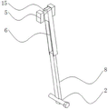
The equal sliding connection of surface of every backup pad 8 has lagging 6, and through lagging 6 and backup pad 8, two device cooperations can stretch out and draw back, conveniently receive and release, and backup pad 8 packs up the back and need put on shelving piece 7, and the top of chassis 1 is provided with the concatenation and encloses fender 4, and every concatenation encloses the surface that keeps off 4 all with the inner wall fixed connection of splice frame 9.
Every concatenation is enclosed the below that keeps off 4 and is provided with end and encloses fender 3, encloses the surface that keeps off 3 at every end and all with chassis 1's inner wall fixed connection, the inner wall of every lagging 6 all rotates and is connected with pivot 15, the equal fixed mounting in front and the back of splice rack 9 has the same supporting shoe 5 of a plurality of, the inner wall of every supporting shoe 5 all with the outer fixed connection of pivot 15, through pivot 15 and supporting shoe 5 for the rotation of lagging 6.
The utility model discloses a theory of operation is: firstly, when needing to use in the work progress and enclosing the fender, can be with chassis 1 pre-buried in the ground, fix chassis 1 with fixed column 11, strengthen chassis 1's stability can, and then can normally use chassis 1 and end to enclose fender 3, when the height that encloses fender 3 at the end can not satisfy the requirement in the work progress, because it is more time-consuming and laboursome to change the higher fender that encloses of height, need all to demolish the back and install, at this moment, can use splice frame 9, when connecting splice frame 9 and chassis 1, insert connecting rod 13 in jack 10, insert the in-process of jack 10 at connecting rod 13, frame groove 14 can cover gradually on chassis 1, thereby use the concatenation to enclose fender 4 and increase end and enclose the height that keeps off 3, because the increase that encloses the fender height, for keeping its original intensity, can rotate lagging 6, lagging 6 leaves and shelve piece 7 after, backup pad 8 can stretch out from lagging 6, put the backup pad 8 that will stretch out in fixed slot 12, fix backup pad 8 with fixing bolt 2, thereby make backup pad 8 and lagging 6 cooperate with the support that the splice frame is enclosed to support 4.
It is to be understood that the present invention has been described with reference to certain embodiments, and that various changes or equivalents may be substituted for elements thereof by those skilled in the art without departing from the spirit and scope of the invention. In addition, many modifications may be made to adapt a particular situation or material to the teachings of the invention without departing from the essential scope thereof. Therefore, the present invention is not limited to the specific embodiments disclosed herein, and all embodiments falling within the scope of the claims of the present application are intended to be covered by the present invention.
Claims (8)
1. The utility model provides a fender is enclosed in municipal works construction, includes chassis (1), splice frame (9) and frame groove (14), its characterized in that: the bottom surface of concatenation frame (9) contacts with the upper surface of chassis (1), every the inside of frame groove (14) all with the surface looks joint of chassis (1), every the equal fixed mounting of the interior roof of frame groove (14) has connecting rod (13), three jack (10) have been seted up to the upper surface of chassis (1), a plurality of same fixed slot (12), every have been seted up to the upper surface of chassis (1) the equal joint in inside of fixed slot (12) has backup pad (8), every the equal sliding connection in surface of backup pad (8) has lagging (6), and the inner wall of every lagging (6) all rotates and is connected with pivot (15), the front of concatenation frame (9) and the equal fixed mounting in the back have the same supporting shoe (5) of a plurality of.
2. The municipal construction fence according to claim 1, wherein: the outer surface of each connecting rod (13) is in contact with the inner wall of the jack (10), and the inner wall of each supporting block (5) is fixedly connected with the outer surface of the rotating shaft (15).
3. The municipal construction fence according to claim 1, wherein: a plurality of identical laying blocks (7) are arranged above the bottom frame (1), and the outer surface of each laying block (7) is fixedly connected with the outer surface of the splicing frame (9).
4. The municipal construction fence according to claim 1, wherein: a plurality of identical fixing columns (11) are arranged below the splicing frame (9), and the outer surface of each fixing column (11) is fixedly connected with the inner wall of the bottom frame (1).
5. The municipal construction fence according to claim 1, wherein: the back and the front of the underframe (1) are provided with three threaded holes (16), and the inside of each threaded hole (16) is communicated with the inside of the fixing groove (12).
6. The municipal construction fence according to claim 5, wherein: every the equal threaded connection of inner wall of backup pad (8) has fixing bolt (2), every the surface of fixing bolt (2) all with the inner wall threaded connection of screw hole (16).
7. The municipal construction fence according to claim 1, wherein: the top of chassis (1) is provided with the concatenation and encloses fender (4), every the concatenation encloses the surface that keeps off (4) and all with the inner wall fixed connection of concatenation frame (9).
8. The municipal construction fence according to claim 7, wherein: a bottom surrounding baffle (3) is arranged below each splicing surrounding baffle (4), and the outer surface of each bottom surrounding baffle (3) is fixedly connected with the inner wall of the bottom frame (1).
Priority Applications (1)
| Application Number | Priority Date | Filing Date | Title |
|---|---|---|---|
| CN202221898109.8U CN217925290U (en) | 2022-07-22 | 2022-07-22 | Fender is enclosed in municipal works construction |
Applications Claiming Priority (1)
| Application Number | Priority Date | Filing Date | Title |
|---|---|---|---|
| CN202221898109.8U CN217925290U (en) | 2022-07-22 | 2022-07-22 | Fender is enclosed in municipal works construction |
Publications (1)
| Publication Number | Publication Date |
|---|---|
| CN217925290U true CN217925290U (en) | 2022-11-29 |
Family
ID=84189756
Family Applications (1)
| Application Number | Title | Priority Date | Filing Date |
|---|---|---|---|
| CN202221898109.8U Active CN217925290U (en) | 2022-07-22 | 2022-07-22 | Fender is enclosed in municipal works construction |
Country Status (1)
| Country | Link |
|---|---|
| CN (1) | CN217925290U (en) |
-
2022
- 2022-07-22 CN CN202221898109.8U patent/CN217925290U/en active Active
Similar Documents
| Publication | Publication Date | Title |
|---|---|---|
| CN217925290U (en) | Fender is enclosed in municipal works construction | |
| CN210577559U (en) | Temporary power utilization cable support for electric engineering construction site | |
| CN215569093U (en) | Surveying and mapping device for informatization management of natural resources | |
| CN108678527B (en) | Auxiliary supporting device | |
| CN211949498U (en) | Movable building scaffold | |
| CN212837906U (en) | Middle-placed walking type end hydraulic support with front beam, top protection and gangue prevention functions | |
| CN211285299U (en) | Protective bracket for bridge construction | |
| CN108678528B (en) | Auxiliary supporting device for preventing telegraph pole from toppling | |
| CN213664641U (en) | Stand bearing device for exhibition | |
| CN219241535U (en) | Protective fence for constructional engineering | |
| CN211186323U (en) | Assembled cabinet | |
| CN216121612U (en) | Temporary cable support for power construction | |
| CN216787770U (en) | Fixing frame for disassembling steel structure | |
| CN210659193U (en) | Movable scaffold for subway tunnel construction | |
| CN218061790U (en) | Fence structure for building construction | |
| CN213805085U (en) | Mountain road protection device for tourism and sightseeing | |
| CN214364686U (en) | Assembled floor | |
| CN219261617U (en) | Assembled stand | |
| CN210622472U (en) | Fender is enclosed with environment-friendly that can reduce dirt to city construction | |
| CN215862093U (en) | Wall-penetrating pipeline connecting and positioning mechanism for water conservancy construction | |
| CN219571441U (en) | Mechanical equipment installation supporting equipment | |
| CN210150234U (en) | Multifunctional device for electromechanical installation of construction engineering | |
| CN217485943U (en) | Portable distribution box | |
| CN215718787U (en) | Supporting device for tunnel building forming | |
| CN220394300U (en) | Steel box girder construction pin-connected panel loading platform |
Legal Events
| Date | Code | Title | Description |
|---|---|---|---|
| GR01 | Patent grant | ||
| GR01 | Patent grant |