CN217906508U - Shoes with training function - Google Patents
Shoes with training function Download PDFInfo
- Publication number
- CN217906508U CN217906508U CN202220864571.XU CN202220864571U CN217906508U CN 217906508 U CN217906508 U CN 217906508U CN 202220864571 U CN202220864571 U CN 202220864571U CN 217906508 U CN217906508 U CN 217906508U
- Authority
- CN
- China
- Prior art keywords
- shoe
- sole body
- support
- sole
- training
- Prior art date
- Legal status (The legal status is an assumption and is not a legal conclusion. Google has not performed a legal analysis and makes no representation as to the accuracy of the status listed.)
- Active
Links
Images


Abstract
The utility model discloses a shoes with training function, including vamp and sole body, the sole body includes insole and the big end, is provided with unstable structure between insole and the big end, and insole, unstable structure and the range upon range of setting of big end, when foot and the contact of sole body, unstable structure atress extrusion produce the physique and change to realize foot and the non-steady contact of sole body. The utility model provides a shoes with training function introduces the notion of wave velocity ball to sports shoes in to realize unstable effect, reach the efficiency of training through daily dress, and can improve human energy consumption.
Description
Technical Field
The utility model relates to a technical field of shoes especially relates to a shoes with training function.
Background
The core strength training is the middle link of the human body, the middle link refers to the area below the shoulder joint and above the hip joint, including the pelvis, is a whole formed by the waist, the pelvis and the hip joint, and comprises 29 muscles. The core muscle group plays roles of stabilizing the center of gravity, transmitting strength and the like, is the main link of overall exertion, and plays a pivotal role in starting up and down the activities and exertion of upper and lower limbs. The powerful core muscle group plays a stabilizing and supporting role in body posture, motor skills and special technical actions in sports. Therefore, the core muscle group is certainly well trained in people with beautiful and straight postures and strong body control force and balance force.
In the prior art, "instability" is achieved by reducing the stabilizing surface area and contact points, leading to greater responses to increased strength of the core musculature to maintain balance and spine stability, requiring mobilization of more muscles, particularly at the core site, improved posture control, reduced recurrence of musculoskeletal injury, improved control of the nervous system over the locomotor system, increased number of muscle activations, facilitated recruitment of locomotor units, improved postural control, stabilized center of gravity, improved dynamic and static balance, improved proprioception, and improved lower limb muscle strength.
With the increasing awareness of consumers in training and the increasing demand for training equipment, it is becoming a trend to design a sports shoe with training function. The sports shoes that have training function that common on the existing market is the negative heel shoes, and its design is the imitation walking on the slope originally to reinforcing and exercise trunk and low limbs muscle strength. The heel of a common sports shoe is about 1.5cm higher than the toe cap, and the toe cap of a negative heel shoe is about 1.5cm higher than the heel, and can generate dorsiflexion of about 10 degrees when the shoe is upright. The function principle of the negative heel shoes is to force the gravity center of the human body to move backwards, so that the gravity center position of the human body is close to the spine, the spine keeps a straight posture, and the functions of posture correction, fat burning, functional exercise and the like can be realized. However, the existing negative heel shoes still have some defects: the multifunctional training device is simple in design and structure, single in function, poor in wearing comfort level, not suitable for daily wearing, poor in training effect, incapable of maintaining self balance in the wearing training process and easy to hurt.
SUMMERY OF THE UTILITY MODEL
For solving the technical problems of simple structure, single function and poor wearing comfort of the traditional negative heel shoes mentioned in the background art, the shoes with the training function are provided, the training effect can be achieved through daily wearing, and the energy consumption of the human body is improved.
In order to achieve the above object, the utility model discloses a specific technical scheme as follows of shoes with training function:
the utility model provides a shoes with training function, includes vamp and sole body, and the sole body includes insole and the big end, is provided with unstable structure between insole and the big end, and insole, unstable structure and the range upon range of setting in order forming the sole body at the big end, and when foot and the contact of sole body, unstable structure atress extrusion produced the physique and changes to realize foot and the non-stationary contact of sole body.
Further, the unstable structure is arranged at the half sole part of the sole body.
Further, the maximum thickness of the half sole part of the sole body is larger than the maximum thickness of the heel part of the sole body.
Further, the difference range of the maximum thickness of the half sole part of the sole body and the maximum thickness of the heel part of the sole body is 10-20 mm.
Further, a supporting plate is arranged between the insole and the unstable structure and extends to the middle foot part of the sole body.
Furthermore, the supporting plate comprises a bearing part and a supporting part, the bearing part is connected with the supporting part to form an installation position of the unstable structure, and the supporting part limits the unstable structure to move in the sole body along the length direction of the sole body.
Further, the support plate includes an anti-twisting portion disposed at the midfoot portion to prevent pronation or supination of the arch region.
Further, the unstable structure is a balloon.
Further, the gasbag includes first laminating portion and second laminating portion, and the supporting part includes first supporting part and second supporting part, and first laminating portion offsets with first supporting part, and second laminating portion offsets with the second supporting part, and first supporting part and second supporting part move along sole body length direction with first laminating portion of restriction and second laminating portion.
Further, the gasbag still includes first side portion laminating portion and second side portion laminating portion, and the outsole includes first body, and the both sides of first body set up first fixed part, and first side portion laminating portion second side portion laminating portion laminates with first fixed part respectively mutually, and first fixed part extends to the lateral wall in insole to avoid the physique displacement of gasbag.
Further, set up first bearing structure and second bearing structure on the first body, the first laminating portion of first bearing structure bearing gasbag, the second laminating portion of second bearing structure bearing gasbag.
Further, the hardness of the first supporting structure and the second supporting structure is smaller than that of the first fixing portion and the second fixing portion, so that a wearer can move and walk along the length direction of the sole body.
Further, the outsole still includes the second body, and the second body links to each other with first body, and the both sides of second body are provided with the second fixed part, and the both sides laminating setting at second fixed part and insole heel position.
Further, the first fixing portion and the second fixing portion include at least one inverted V-shaped supporter to support and protect the foot.
Further, the middle part of the second body is provided with a hollow structure.
The utility model discloses a shoes with training function has following advantage:
the utility model provides a shoes with training function introduces the notion of wave velocity ball to the sports shoes in to realize unstable effect, reach the efficiency of training through daily dress, and can improve human energy consumption.
Drawings
FIG. 1 is an exploded view of a shoe with training function according to the present invention;
FIG. 2 is a schematic view of the whole structure of the shoe with training function of the present invention;
FIG. 3 is a schematic structural view of the midsole of the shoe with training function of the present invention;
FIG. 4 is a schematic view of a support plate of the present invention;
FIG. 5 is a top view of a support plate in the shoe with training function of the present invention;
FIG. 6 is a bottom view of the support plate of the shoe with training function of the present invention;
FIG. 7 is a schematic view of the structure of the bladder in the shoe with training function of the present invention;
FIG. 8 is a top view of the bladder of the shoe with training function of the present invention;
FIG. 9 is a side view of the bladder of the shoe with training function of the present invention;
FIG. 10 is a schematic view of the middle sole and the outsole of the shoe with training function according to the present invention;
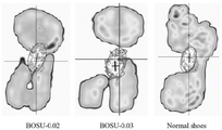
FIG. 11 is a schematic view showing the simulation of the lower limb stability and the change of the sole pressure when the shoes with training function and the standard shoes with different air pressures are walking and standing statically in the embodiment of the present invention;
fig. 12 is a simulation diagram of the lower limb stability and plantar pressure test results of shoes with training functions and standard shoes with different air pressures when walking and standing statically in the embodiment of the present invention.
Detailed Description
In order to make the objects, technical solutions and advantages of the embodiments of the present invention clearer, the embodiments of the present invention will be clearly and completely described below with reference to the accompanying drawings in the embodiments of the present invention, and it is obvious that the described embodiments are some, but not all, embodiments of the present invention. Based on the embodiments in the present invention, all other embodiments obtained by those skilled in the art without creative efforts belong to the protection scope of the present invention.
The technical features mentioned in the different embodiments of the invention described below can be combined with each other as long as they do not conflict with each other.
The following describes the shoes with training function according to the present invention with reference to fig. 1 to 12.
Wave speed balls, also known as semi-circular balance balls, are a device for exercising balance force. Similar to dividing a complete exercise ball into two parts, installing a base on a plane, the wave velocity ball has two surfaces, each surface can assist in exercise, and the wave velocity ball mainly strengthens core muscle groups and can exercise pectoral muscles, shoulder muscles, abdominal muscles and the like. The utility model provides a shoes with training function introduces the notion of wave velocity ball to shoes in to realize unstable efficiency, reach the efficiency of training through daily dress, and improve human energy consumption.
The utility model provides a shoes with training function, including vamp and sole body, the sole body includes preceding palm position, well foot position and heel position, and wherein, preceding palm position is the position of sole body corresponding human foot preceding sole, and well foot position is the position that the sole body corresponds human foot arch of foot region, and the heel position is the position that the sole body corresponds human foot heel.
As shown in fig. 1 and 2, the sole body includes a midsole 1, a support plate 2, an unstable structure, and an outsole 4, and the midsole 1, the support plate 2, the unstable structure, and the outsole 4 are stacked and bonded in multiple layers to form the sole body. The unstable structure is equivalent to the effect of a wave velocity ball, and when the foot is contacted with the sole body, the unstable structure is stressed and extruded to generate body change so as to realize the unstable contact of the foot and the sole body.
Further, unstable structure can set up the half sole position at the sole body, and the half sole position maximum thickness of sole body is greater than the heel position maximum thickness of sole body. The negative heel shoes can play a role in strengthening and training the muscle strength of the trunk and the lower limbs in the daily use process. Therefore, the utility model provides a shoes with training function can strengthen and temper human core strength simultaneously, reaches daily dress and can realize the purpose of training.
The maximum thickness at sole body half sole position is greater than the maximum thickness at sole body heel position and just can realize the training effect of burden with shoes, can reach the effect of taking exercise through daily dress. As a preferred embodiment, the thickness difference characteristic after the sole body is combined is mainly referred to according to the following numerical values, the maximum thickness of the forefoot portion is 20mm to 50mm, the maximum thickness of the heel portion is 20mm to 50mm, and the difference range between the maximum thickness of the forefoot portion of the sole body and the maximum thickness of the heel portion of the sole body is set to 10mm to 20mm. Of course, it should be understood that the above values are only set by the above parameters, and the maximum thickness is the direction extending from the outsole 4 of the sole body to the midsole 1, and is called the thickness. Therefore, when a user wears the sole body, the half sole part is higher than the heel part, the gravity center of the human body is forced to move backwards, the gravity center position of the human body is close to the spine, the spine keeps a straight posture, and the functions of posture correction, fat burning, functional exercise and the like can be realized.
As shown in fig. 3, the midsole 1 is disposed on the uppermost layer of the sole body, and the midsole 1 contacts with the sole of the foot, so that the midsole 1 may be made of a supercritical bead foaming material, which may be one of a nylon elastomer, a thermoplastic polyurethane, and a polyether ester elastomer. The material is characterized in that the hardness (Asker C) is 42 +/-3, the density is 0.10-0.14G/cm < 3>, the rebound resilience is 75% -85%, and the shock absorption (Peak G) is 6-12. The material is light, soft and elastic, and can provide excellent shock absorption and rebound effects for the middle foot part to the half sole part of the human foot during running. Of course, it is understood that the midsole 1 may be made of one, two or more of nylon elastomer, thermoplastic polyurethane (including aromatic type and aliphatic type), cast polyurethane, millable polyurethane, thermoplastic polyether ester elastomer, ethylene-octene copolymer, ethylene-octene block copolymer, ethylene-vinyl acetate copolymer, styrene-butadiene-styrene block copolymer, hydrogenated styrene-butadiene-styrene block copolymer, high styrene rubber, brominated butyl rubber, butadiene rubber, silicone rubber, ethylene propylene diene monomer rubber, natural rubber, isoprene rubber, nitrile rubber, chloroprene rubber, by supercritical foaming or chemical foaming.
As shown in fig. 4 to 6, the supporting plate 2 includes a supporting portion 21 and a supporting portion, the supporting portion 21 and the supporting portion are connected to form an installation position of the unstable structure, and the supporting portion limits the movement of the unstable structure in the sole body along the length direction of the sole body. The bottom surface of the supporting part 21 is attached to the unstable structure, the supporting part 21 of the supporting plate 2 is a plate-shaped structure with a plane, and the supporting part 21 is attached to the unstable structure to support the foot. As a preferred embodiment, the shape of the supporting part 21 is matched with that of the unstable structure, and the supporting part 21 is attached to the upper surface of the unstable structure, so that the comfort of the half sole part can be effectively ensured when the half sole part is worn. Of course, it can be understood that the supporting portion 21 is equivalent to a supporting base of the wave velocity ball, the unstable structure disposed below the supporting portion 21 is equivalent to an unstable ball of the wave velocity ball, and the foot portion is in contact with the supporting portion 21, so that the unstable structure is in an unstable state, thereby achieving the training effect.
In a preferred embodiment, the support portion 21 of the support plate 2 is required to support an unstable structure, and therefore, the support plate 2 is generally made of a hard material. The shore D hardness is 50-95, the supporting plate 2 made of other hard materials can be made of phenolic resin or thermoplastic resin, thermoplastic polyurethane, polycarbonate, polymethyl methacrylate, nylon elastomer, polyether ester elastomer, polyketone, polyether ether ketone, polyether ketone, polyether sulfone, polyphenylene sulfide, ABS (acrylonitrile-butadiene-styrene copolymer) and composite materials formed by the supporting plate and inorganic filler or long fibers or short fibers.
Of course, it can be understood that the supporting portion 21 and the supporting portion of the supporting plate 2 are integrally formed, the first supporting portion 23 and the second supporting portion 24 are disposed at two ends of the supporting portion 21 along the length direction of the sole body, the first supporting portion 23 and the second supporting portion 24 are respectively disposed at the front end and the rear end of the supporting portion 21, the front end is disposed at the forefoot portion, and the rear end is disposed at the midfoot portion, so that the supporting plate 2 is abutted to the unstable structure, thereby restricting the movement of the unstable structure along the length direction of the sole body.
As a preferred embodiment, the first and second support portions 23 and 24 are configured to fit the front and rear ends of the unstable structure, respectively, to abut the support plate 2 against the unstable structure.
Furthermore, the supporting plate 2 further comprises an anti-torsion portion 22, the anti-torsion portion 22 is arranged at the middle foot position, so that the excessive inward rotation or outward rotation of the arch region is prevented in the training process, and a better stable and anti-torsion effect can be achieved. The structure of the anti-torsion portion 22 is a strip-shaped plate-shaped structure, the end of the anti-torsion portion 22 is arranged at the middle foot part, and concave arcs are arranged on two sides of the anti-torsion portion 22, so that the sole body can ensure the light weight design and simultaneously prevent the foot from generating large internal rotation or external rotation in the training process.
The non-stable structure is the balloon 3 as a preferred example, but it is understood that the non-stable structure may be configured in other structures, for example, the non-stable structure may be filled with a flowable liquid or gel ice, and instability of the non-stable structure may be achieved. The unstable structure will be described as an example of the balloon 3.
As shown in fig. 7 to 9, the shape of the airbag 3 and the shape of the receiver 21 are adapted so that both ends of the airbag 3 abut against the front and rear ends of the receiver 21. The airbag 3 includes a first attaching portion 33 and a second attaching portion 31, the supporting portion includes a first supporting portion 23 and a second supporting portion 24, the first attaching portion 33 abuts against the first supporting portion 23, the second attaching portion 31 abuts against the second supporting portion 24, and the first supporting portion 23 and the second supporting portion 24 limit the first attaching portion 33 and the second attaching portion 31 to move along the length direction of the sole body.
Specifically, the first attaching portion 33 is disposed at the front end of the front sole portion, the second attaching portion 31 is disposed at the rear end of the front sole portion, the first attaching portion 33 is a first assembling groove disposed along the direction of the support plate 2, the front end of the first support portion 23 is arc-shaped, so that the front end of the first support portion 23 is in clamping connection with the assembling groove, and the first support portion 23 abuts against the first attaching portion 33. The second attaching portion 31 is configured as an arc-shaped end face, the second supporting portion 24 is configured on the bottom surface of the supporting plate 2, the second supporting portion 24 is a second assembling groove, and the second assembling groove abuts against the end face of the second attaching portion 31, so that the front end and the rear end of the airbag 3 abut against the front end and the rear end of the supporting plate 2 respectively, and excessive form displacement of the airbag 3 is avoided.
Further, the both sides of gasbag 3 set up first side laminating portion 32 and second side laminating portion 34, and first side laminating portion 32 and second side laminating portion 34 laminate with undersole 4 mutually respectively, and the bearing structure who sets up on the undersole 4 extends to insole 1, wraps up gasbag 3 completely to provide support nature and stability. The thickness of first side laminating portion 32 and second side laminating portion 34 and first laminating portion 33 and second laminating portion 31 is greater than the thickness of other positions of gasbag 3, through four laminating parts all around, guarantees that gasbag 3 can provide comparatively reasonable unstable training effect in the half sole below, avoids too much physique displacement, leads to gasbag 3 downside holding surface area grow, influences unstable training effect.
Further, 3 inside gas that injects into of gasbag can adjust according to the training degree, adjusts 3 gasbag's the internal pressure of utricule to reach different training effects, atmospheric pressure is big more, and the utricule is more bloated, and is less with the contact on ground, can provide unstable effect more.
Further, the material of the air bag 3 is one or more of thermoplastic polyurethane, nylon, polyethylene, polypropylene, ethylene-octene copolymer, ethylene-vinyl acetate copolymer and ethylene/vinyl alcohol copolymer, and the two layers are prepared by a multilayer co-extrusion process, wherein the air bag 3 is characterized in that the air pressure is 0.01-0.15MPa, the wall thickness of the air bag 3 is 0.1-2.0mm, and the maximum thickness of the air bag 3 after being inflated is 5-40mm.
As shown in fig. 10, the outsole 4 is disposed at the lowest layer of the sole body and contacts with the ground, and the outsole 4 may be made of a casting polyurethane material, or may be made of one, two or more materials selected from nylon elastomer, thermoplastic polyurethane (including aromatic type and aliphatic type), casting polyurethane, mixing polyurethane, thermoplastic polyether ester elastomer, ethylene-octene copolymer, ethylene-octene block copolymer, ethylene-vinyl acetate copolymer, styrene-butadiene-styrene block copolymer, hydrogenated styrene-butadiene-styrene block copolymer, high styrene rubber, bromobutyl rubber, butadiene rubber, silicone rubber, ethylene propylene diene monomer, natural rubber, isoprene rubber, nitrile rubber, and chloroprene rubber.
Further, outsole 4 includes first body and second body, and first body and second body link to each other, and first body and second body be integrated into one piece. The first body is arranged at the half sole part, and the second body is arranged at the midfoot part and the heel part. The first body is provided with a first supporting structure 49 and a second supporting structure 410, the first supporting structure 49 is arranged at the front end of the front palm part, the second supporting structure 410 is arranged at the rear end of the front palm part, and the air bag 3 is attached to the outsole 4. A first edge of the airbag 3 is provided at the front end of the front sole portion, and a second edge of the airbag 3 is provided at the rear end of the front sole portion. The first edge of the air-bag 3 is in contact with the first bearing structure 49 so that the first bearing structure 49 supports the first edge of the air-bag 3. The second edge of the bladder 3 contacts the second support structure 410 to enable the second support structure 410 to support the second edge of the bladder 3 so that the upper and lower surfaces of the bladder 3 are wrapped within the sole body by the support plate 2 and outsole 4.
Further, the opposite two side walls of the first body are respectively provided with a first supporting member 41, a second supporting member 42, a third supporting member 47 and a fourth supporting member 48, and the first supporting member 41, the second supporting member 42, the third supporting member 47 and the fourth supporting member 48 are respectively arranged along the side wall of the outsole 4 towards the direction of the midsole 1 and are attached to the side wall of the midsole 1 to form the sole body. The first and second support members 41 and 42 are attached to the first side attachment portion 32 of the bladder 3, and the third and fourth support members 47 and 48 are combined with the second side attachment portion 34 of the bladder 3, so that the first, second, third, and fourth support members 41, 42, 47, and 48 wrap the bladder 3 within the sole body to provide support and stability of the sole body.
In a preferred embodiment, the first support 41, the second support 42, the third support 47 and the fourth support 48 are symmetrically disposed on two opposite sidewalls of the outsole 4, the first support 41, the second support 42, the third support 47 and the fourth support 48 are in an inverted V-shaped structure, the sidewall of the midsole 1 is provided with a first groove 11 and a second groove 12, the positions of the first groove 11 and the second groove 12 correspond to the first support 41, the second support 42, the third support 47 and the fourth support 48, and similarly, the first groove 11 and the second groove 12 are also in an inverted V-shaped structure, so that the first support 41, the second support 42, the third support 47 and the fourth support 48 are respectively attached to the first groove 11 and the second groove 12. The support piece of the inverted V-shaped structure can not only play a powerful role in supporting, but also ensure the lightness, and the four support pieces can ensure that the air bag 3 does not shift too much on the left side and the right side of the front palm, so that the air bag 3 is enabled to gather under the front palm with good pressure, and an unstable training state is provided.
Further, the first support member 41, the second support member 42, the third support member 47 and the fourth support member 48 are stiffer than the first support structure 49 and the second support structure 410 to facilitate movement and walking in the fore-aft direction for the wearer.
Furthermore, the second body is arranged at the heel part of the outsole 4, the fifth support member 43, the sixth support member 44, the seventh support member 45 and the eighth support member 46 are arranged on two opposite side walls of the second body, the fifth support member 43, the sixth support member 44, the seventh support member 45 and the eighth support member 46 are in an inverted V-shaped structure, the third groove 13 is arranged on the side wall of the midsole 1, the position of the third groove 13 corresponds to the fifth support member 43, the sixth support member 44, the seventh support member 45 and the eighth support member 46, so that the fifth support member 43, the sixth support member 44, the seventh support member 45, the eighth support member 46 and the third groove 13 are attached to each other, similarly, the fixing grooves are also in an inverted V-shaped structure, the supporting and protecting effects are achieved, and the weight of the support members is reduced.
Further, the middle part of the second body is arranged to be a hollow structure, so that the weight of the sole body is reduced, and meanwhile the flexibility of the foot of a user can be improved.
As shown in fig. 11 and 12, for the shoe design experimental scheme provided by the present invention:
(1) the test purpose is as follows: the air pressure of the air bag 3 is 0.02MPa and 0.03MPa, and the lower limb stability and the change condition of the sole pressure when the standard shoe is walking and standing are compared with the two types of shoes with different air pressures and training functions.
(2) Subject: several general public US7 foot size female subjects were recruited as subjects.
(3) Experimental equipment: rsscan plantar pressure plate and Noraxon surface myoelectricity.
(4) The experimental steps are as follows: the subject passes through the timer and the plantar pressure plate at the natural walking speed, and the plantar pressure and the electromyogram data are collected at the same time. Three walks per shoe pair, the speed between the three walks was controlled using a timer to minimize the difference, after which a static fatigue test of one foot open to the eyes for 120s was performed on a plantar pressure plate. The comparison of the shoes with training function and the conventional shoes through biomechanical test has the following results:
as shown in fig. 12, COP indices (left and right, front and back): BOSU0.03> BOSU0.02> Normal, COP means Center of pressure, represents the change condition of the pressure Center of gravity of the human body, and the larger the fluctuation is, the more unstable the fluctuation is. COP travel distance: BOSU0.03> BOSU0.02> Normal, the larger the travel distance the more unstable. Elliptical area, radius: BOSU0.03> BOSU0.02> Normal, the larger the elliptical area the more unstable.
Because the front part of the shoe with the training function is high and the back part of the shoe with the training function is high, more muscle fibers are required to be additionally used for transition to the stretching and the pedaling in the middle and later periods of the support, the front sole height is expected to be standard shoes < shoes with small air pressure < shoes with large air pressure, and therefore the shoes with large air pressure need to use more muscle fibers to maintain the pace than the front two shoes. The shoes with training function with large air pressure need more fibers of medial muscles of gastrocnemius to participate in work when being used for pedaling and stretching, which means that the gastrocnemius needs to consume more energy in the later period of walking.
The utility model provides a shoes with training function introduces the notion of wave velocity ball to sports shoes in to realize unstable effect, reach the efficiency of training through daily dress, and can improve human energy consumption.
It is to be understood that the present invention has been described with reference to certain embodiments, and that various changes or equivalents may be substituted for elements thereof by those skilled in the art without departing from the spirit and scope of the invention. In addition, many modifications may be made to adapt a particular situation or material to the teachings of the invention without departing from the essential scope thereof. Therefore, the present invention is not limited to the specific embodiments disclosed herein, and all embodiments falling within the scope of the claims of the present application are intended to be covered by the present invention.
Claims (14)
1. The utility model provides a shoes with training function, includes vamp and sole body, its characterized in that, and the sole body includes insole and the big end, is provided with unstable structure between insole and the big end, and insole, unstable structure and the range upon range of setting of big end set up the backup pad between insole and the unstable structure, and the backup pad extends to the mid-foot position setting of sole body, and when foot and the contact of sole body, unstable structure atress extrusion production physique change to realize foot and the non-stationary contact of sole body.
2. The shoe with exercise function according to claim 1, wherein the non-stable structure is provided at a half sole portion of the sole body.
3. The shoe with exercise function according to claim 2, wherein the maximum thickness of the half sole portion of the shoe sole body is greater than the maximum thickness of the heel portion of the shoe sole body.
4. The shoe having an exercise function according to claim 3, wherein the difference between the maximum thickness of the ball portion of the sole body and the maximum thickness of the heel portion of the sole body ranges from 10mm to 20mm.
5. The shoe with exercise function according to claim 1, wherein the support plate includes a support portion and a support portion, the support portion and the support portion are connected to form a mounting position of the unstable structure, and the support portion limits the unstable structure from moving in the sole body along the length direction of the sole body.
6. The shoe with exercise function according to claim 1, wherein the support plate further comprises an anti-twist portion provided at the midfoot region to prevent the inner or outer rotation of the arch region.
7. A shoe with training functions according to any one of claims 5 or 6, wherein the non-stabilized structure is a bladder.
8. The shoe with training function according to claim 7, wherein the air bag includes a first attaching portion and a second attaching portion, the support portion includes a first support portion and a second support portion, the first attaching portion abuts against the first support portion, the second attaching portion abuts against the second support portion, and the first support portion and the second support portion restrict the first attaching portion and the second attaching portion from moving in the longitudinal direction of the sole body.
9. The shoe with training function of claim 8, wherein the airbag further comprises a first side attaching portion and a second side attaching portion, the outsole comprises a first body, first fixing portions are disposed on two sides of the first body, the first side attaching portion and the second side attaching portion are respectively attached to the first fixing portions, and the first fixing portions extend to the side walls of the midsole to prevent the body of the airbag from being displaced.
10. The shoe with training function of claim 9, wherein a first supporting structure and a second supporting structure are provided on the first body, the first supporting structure supporting a first edge of the air bag, and the second supporting structure supporting a second edge of the air bag.
11. The shoe with training function of claim 10, wherein the outsole further comprises a second body, the second body is connected to the first body, the second body is provided with second fixing parts at both sides thereof, and the second fixing parts are attached to both sides of the heel portion of the midsole.
12. An exercise shoe according to claim 11 wherein the stiffness of the first support structure and the second support structure is less than the stiffness of the first attachment means and the second attachment means.
13. The shoe with exercise function of claim 11, wherein the first fixing portion and the second fixing portion comprise at least one inverted V-shaped supporter to support and protect the foot.
14. The shoe having training function of claim 11, wherein the middle portion of the second body is provided with a hollow structure.
Priority Applications (1)
| Application Number | Priority Date | Filing Date | Title |
|---|---|---|---|
| CN202220864571.XU CN217906508U (en) | 2022-04-15 | 2022-04-15 | Shoes with training function |
Applications Claiming Priority (1)
| Application Number | Priority Date | Filing Date | Title |
|---|---|---|---|
| CN202220864571.XU CN217906508U (en) | 2022-04-15 | 2022-04-15 | Shoes with training function |
Publications (1)
| Publication Number | Publication Date |
|---|---|
| CN217906508U true CN217906508U (en) | 2022-11-29 |
Family
ID=84175146
Family Applications (1)
| Application Number | Title | Priority Date | Filing Date |
|---|---|---|---|
| CN202220864571.XU Active CN217906508U (en) | 2022-04-15 | 2022-04-15 | Shoes with training function |
Country Status (1)
| Country | Link |
|---|---|
| CN (1) | CN217906508U (en) |
-
2022
- 2022-04-15 CN CN202220864571.XU patent/CN217906508U/en active Active
Similar Documents
| Publication | Publication Date | Title |
|---|---|---|
| US11612211B2 (en) | Sole and article of footwear having a pod assembly | |
| CN112956780B (en) | Article of footwear with stabilizing fence | |
| US10016017B2 (en) | Sole and article of footwear having a pod assembly | |
| US4183156A (en) | Insole construction for articles of footwear | |
| US8307569B2 (en) | Training footwear | |
| EP3379963B1 (en) | Sole, particularly for shoes | |
| US20130212909A1 (en) | Sole And Article Of Footwear Having A Pod Assemby | |
| US8776399B2 (en) | Shoe insole | |
| AU2008243999B2 (en) | An item of footwear | |
| CN104602560A (en) | Footwear sheet and footwear | |
| CN217906508U (en) | Shoes with training function | |
| KR100761897B1 (en) | duplicated shock absorbing shoe-sole | |
| US20030029059A1 (en) | Biomechanical sole unit | |
| KR101463544B1 (en) | Functional molding air insole for impact absorption and pain relieving | |
| CN115644558A (en) | Sole and shoes with training function | |
| JP2004337262A (en) | Shoe | |
| KR101245973B1 (en) | Midsole of shoes | |
| KR200341150Y1 (en) | Health shoes | |
| CN205214368U (en) | Burden is with sole | |
| CN220369566U (en) | Shoe sole and shoe with long-time walking tiredness | |
| KR200431327Y1 (en) | A footwear with springy device at outsole | |
| KR100979262B1 (en) | A health shoes constructed double hills | |
| KR20070110858A (en) | Mechanical cushioning system for footwear | |
| JPH0727307U (en) | Insole structure and insole | |
| KR200413646Y1 (en) | duplicated shock absorbing shoe-sole |
Legal Events
| Date | Code | Title | Description |
|---|---|---|---|
| GR01 | Patent grant | ||
| GR01 | Patent grant |