CN217890534U - Double-abrasive-belt knife grinding device - Google Patents
Double-abrasive-belt knife grinding device Download PDFInfo
- Publication number
- CN217890534U CN217890534U CN202222216702.6U CN202222216702U CN217890534U CN 217890534 U CN217890534 U CN 217890534U CN 202222216702 U CN202222216702 U CN 202222216702U CN 217890534 U CN217890534 U CN 217890534U
- Authority
- CN
- China
- Prior art keywords
- winding roller
- mounting
- belt
- support
- shaft
- Prior art date
- Legal status (The legal status is an assumption and is not a legal conclusion. Google has not performed a legal analysis and makes no representation as to the accuracy of the status listed.)
- Active
Links
Images

Landscapes
- Finish Polishing, Edge Sharpening, And Grinding By Specific Grinding Devices (AREA)
Abstract
The utility model relates to a grinding device field specifically is a two abrasive band knife sharpening device. The device comprises a base, a coarse sand belt grinding cutter assembly, a fine sand belt grinding cutter assembly, a supporting assembly, a driving mechanism and an adjusting assembly; the coarse abrasive belt sharpening assembly comprises a winding roller a, a coarse abrasive belt, a winding roller b, a mounting shaft a, a mounting seat a and a support a, wherein the coarse abrasive belt is wound on the winding roller a and the winding roller b, the winding roller b is arranged on the mounting shaft a, the mounting shaft a is rotatably arranged on the mounting seat a, the mounting seat a is arranged on the support a, and the support a is arranged on the base; the fine abrasive belt sharpening assembly comprises a winding roller c, a fine abrasive belt, a winding roller d, an installation shaft b, an installation frame, a rotating shaft and an installation seat b, wherein the winding roller c is arranged on the rotating shaft, the fine abrasive belt is wound on the winding roller c and the winding roller d, the winding roller d is arranged on the installation shaft b, and the installation shaft b is rotatably arranged on the installation frame. The utility model discloses can carry out the corase grind in proper order to the cutter and grind with the fine grinding and improve the efficiency of whetting a knife.
Description
Technical Field
The utility model relates to a grinding device field especially relates to a two abrasive band knife sharpening device.
Background
Domestic cutter or other cutters use the back for a long time, and the blade can become dull, need use the whetstone to grind the cutter, but to the mode of whetting a knife through the whetstone simply, rely on manual operation completely, manual round trip movement cutter scratches the cutter on the whetstone, whets a knife inefficiency.
SUMMERY OF THE UTILITY MODEL
The utility model discloses the purpose is to the problem that exists among the background art, provides one kind and can carry out the corase grind in proper order to the cutter and grind with the fine grinding and improve the two abrasive band knife sharpening device who whets a knife efficiency.
The technical scheme of the utility model is that the double-abrasive belt knife sharpening device comprises a base, a coarse abrasive belt knife sharpening component, a fine abrasive belt knife sharpening component, a supporting component, a driving mechanism and an adjusting component;
the coarse abrasive belt sharpening assembly comprises a winding roller a, a coarse abrasive belt, a winding roller b, a mounting shaft a, a mounting seat a and a support a, wherein the coarse abrasive belt is wound on the winding roller a and the winding roller b, the winding roller b is arranged on the mounting shaft a, the mounting shaft a is rotatably arranged on the mounting seat a, the mounting seat a is arranged on the support a, and the support a is arranged on the base; the fine sand belt sharpening assembly comprises a winding roller c, a fine sand belt, a winding roller d, a mounting shaft b, a mounting frame, a rotating shaft and a mounting seat b, wherein the winding roller c is arranged on the rotating shaft; the supporting component is arranged on the base and is used for supporting the mounting seat b; the driving mechanism is arranged on the base and is used for driving the winding roller a and the winding roller c to rotate; the adjusting assembly is arranged on the bracket b and is used for adjusting the position of the mounting bracket so as to adjust the tensioning degree of the fine sand belt.
Preferably, the mounting bracket is screwed with a compression bolt a abutting on the mounting shaft b.
Preferably, actuating mechanism includes motor, action wheel, belt and follows the driving wheel, and the motor setting is on the base, and the motor is connected with the action wheel drive, and the action wheel passes through the belt to be connected from the driving wheel, follows the driving wheel setting in the axis of rotation.
Preferably, the supporting component comprises an installation platform and a plurality of groups of installation components, each installation component comprises a screw rod and two nuts, the screw rods are vertically arranged on the base, the screw rods penetrate through the installation platform, the two nuts are in threaded connection with the screw rods, the two nuts are respectively tightly pressed on the upper side surface and the lower side surface of the installation platform, and the installation seat is arranged on the installation platform.
Preferably, the adjusting part includes the link, the slide bar, the elastic component, the guide cylinder, adjusting bolt, clamp bolt b, support b and additional strengthening, the link sets up on the mounting bracket, the slide bar tip is connected with the link, the elastic component is the spring and the cover is established on the slide bar, the elastic component both ends are connected with link and guide cylinder respectively, the guide cylinder sets up on support b, adjusting bolt and guide cylinder threaded connection, adjusting bolt is towards the slide bar, clamp bolt b and guide cylinder threaded connection, clamp bolt b butt is on the slide bar, the additional strengthening both ends are connected with screw rod and support b respectively, support b sets up on the base.
Preferably, a supporting table a is arranged on the base and is supported on the top surface of the inner side of the coarse sand belt; and a support platform b is arranged on the support b and supported on the inner top surface of the fine sand belt.
Compared with the prior art, the utility model discloses following profitable technological effect has:
the utility model discloses can carry out the corase grind in proper order to the cutter and grind with the fine grinding and improve the efficiency of whetting a knife. When the tool sharpener is used, a tool is firstly polished on a coarse abrasive belt and then polished on a fine abrasive belt, the tool can be rapidly sharpened by the progressive polishing mode, time is saved, and the sharpening efficiency is improved. The tensioning degree of the fine abrasive belt is adjusted through the adjusting assembly, so that the polishing condition is adjusted, the fine abrasive belt is tensioned more, the fine abrasive belt can rotate along with the winding roller c and the winding roller d, the rotating speed of the fine abrasive belt can be increased more, and the polishing speed and efficiency of the cutter can be increased more.
Drawings
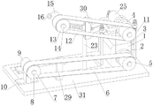
Fig. 1 and fig. 2 are schematic structural diagrams of two viewing angles according to an embodiment of the present invention.
Reference numerals are as follows: 1. a motor; 2. a driving wheel; 3. a belt; 4. a driven wheel; 5. a winding roller a; 6. a coarse abrasive belt; 7. a wind roller b; 8. mounting a shaft a; 9. a mounting seat a; 10. a bracket a; 11. a wind roller c; 12. a fine abrasive belt; 13. a wind-up roller d; 14. mounting a shaft b; 15. a mounting frame; 16. a compression bolt a; 17. a connecting frame; 18. a slide bar; 19. an elastic member; 20. a guide cylinder; 21. adjusting the bolt; 22. a compression bolt b; 23. a bracket b; 231. a reinforcing frame; 24. a rotating shaft; 25. a mounting seat b; 26. an installation table; 27. a screw; 28. a nut; 29. a support table a; 30. a support table b; 31. a base.
Detailed Description
Example one
As shown in fig. 1-2, the double-abrasive-belt knife sharpening device provided in this embodiment includes a base 31, a coarse-abrasive-belt knife sharpening assembly, a fine-abrasive-belt knife sharpening assembly, a supporting assembly, a driving mechanism, and an adjusting assembly;
the coarse abrasive belt sharpening assembly comprises a winding roller a5, a coarse abrasive belt 6, a winding roller b7, a mounting shaft a8, a mounting seat a9 and a support a10, wherein the coarse abrasive belt 6 is wound on the winding roller a5 and the winding roller b7, the winding roller b7 is arranged on the mounting shaft a8, the mounting shaft a8 is rotatably arranged on the mounting seat a9, the mounting seat a9 is arranged on the support a10, and the support a10 is arranged on a base 31; the fine sand belt sharpening assembly comprises a winding roller c11, a fine sand belt 12, a winding roller d13, a mounting shaft b14, a mounting frame 15, a rotating shaft 24 and a mounting seat b25, wherein the winding roller c11 is arranged on the rotating shaft 24, the fine sand belt 12 is wound on the winding roller c11 and the winding roller d13, the winding roller d13 is arranged on the mounting shaft b14, the mounting shaft b14 is rotatably arranged on the mounting frame 15, and the rotating shaft 24 is rotatably arranged on the mounting seat b25; the supporting component is arranged on the base 31 and used for supporting the mounting seat b25; the driving mechanism is arranged on the base 31 and is used for driving the winding roller a5 and the winding roller c11 to rotate; an adjustment assembly is provided on bracket b23 and is used to adjust the position of mounting bracket 15 to adjust the tension of the abrasive belt 12.
The embodiment can carry out rough grinding and fine grinding on the cutter in sequence and improve the grinding efficiency. When the tool sharpener is used, a tool is firstly ground on the thick abrasive belt 6 and then ground on the thin abrasive belt 12, the tool can be rapidly sharpened by the progressive grinding mode, time is saved, and the sharpening efficiency is improved. The tensioning degree of the fine abrasive belt 12 is adjusted through the adjusting assembly, so that the grinding condition is adjusted, the more the fine abrasive belt 12 is tensioned, the more the fine abrasive belt 12 can rotate along with the winding roller c11 and the winding roller d13, the more the rotating speed of the fine abrasive belt 12 can be increased, and the grinding speed and efficiency of the cutter can be increased.
Example two
As shown in fig. 1, in the present embodiment, compared to the first embodiment, in the first embodiment, the mounting frame 15 is connected with the pressing bolt a16 abutting on the mounting shaft b14 in a threaded manner, the slower the pressing bolt a16 presses against the mounting shaft b14, the slower the rotation speed of the mounting shaft b14 is, the slower the rotation speed of the sanding belt 12 is, so as to slow down the sanding speed of the tool, and the sanding process is safer.
EXAMPLE III
As shown in fig. 1-2, compared with the first embodiment, in the first embodiment, the driving mechanism includes a motor 1, a driving wheel 2, a belt 3, and a driven wheel 4, the motor 1 is disposed on the base 31, the motor 1 is in driving connection with the driving wheel 2, the driving wheel 2 is connected with the driven wheel 4 through the belt 3, the driven wheel 4 is disposed on the rotating shaft 24, the motor 1 can drive the driving wheel 2 to rotate, the driving wheel 2 drives the driven wheel 4 to rotate through the belt 3, the driven wheel 4 drives the rotating shaft 24 to rotate, so as to rotate the winding roller c11, and drive the fine abrasive belt 12 to move.
Example four
As shown in fig. 1-2, compared with the third embodiment, in the third embodiment, the supporting component includes an installation table 26 and a plurality of sets of installation components, each installation component includes a screw 27 and two nuts 28, the screw 27 is vertically disposed on a base 31, the screw 27 penetrates through the installation table 26, both the nuts 28 are in threaded connection with the screw 27, and the two nuts 28 are respectively pressed on the upper and lower side surfaces of the installation table 26, an installation seat b25 is disposed on the installation table 26, the installation table 26 can be fixed by the two nuts 28, so as to determine the position of the installation seat b25, the threaded connection position of the two nuts 28 on the screw 27 can be adjusted, so as to adjust the height of the installation table 26, and further adjust the tensioning degree of the belt 3, and can be installed conveniently.
The adjusting assembly comprises a connecting frame 17, a sliding rod 18, an elastic piece 19, a guide cylinder 20, an adjusting bolt 21, a pressing bolt b22, a support b23 and a reinforcing frame 231, the connecting frame 17 is arranged on the mounting frame 15, the end portion of the sliding rod 18 is connected with the connecting frame 17, the elastic piece 19 is a spring and is sleeved on the sliding rod 18, two ends of the elastic piece 19 are respectively connected with the connecting frame 17 and the guide cylinder 20, the guide cylinder 20 is arranged on the support b23, the adjusting bolt 21 is in threaded connection with the guide cylinder 20, the adjusting bolt 21 faces the sliding rod 18, the pressing bolt b22 is in threaded connection with the guide cylinder 20, the pressing bolt b22 abuts against the sliding rod 18, two ends of the reinforcing frame 231 are respectively connected with a screw 27 and the support b23, and the support b23 is arranged on the base 31. The sliding rod 18 can be tightly pushed by rotating the position of the adjusting bolt 21, when the adjusting bolt 21 is screwed in, the connecting frame 17 is pushed outwards by the sliding rod 18, the connecting frame 17 drives the mounting frame 15 to move outwards, the distance between the winding roller c11 and the winding roller d13 is increased, the tensioning degree of the fine abrasive belt 12 is increased, the cutter is conveniently sharpened, and the elastic piece 19 is stretched; when the adjusting bolt 21 is loosened, the elastic member 19 is loosened and the fine abrasive belt 12 becomes loosened.
A supporting table a29 is arranged on the base 31, the supporting table a29 is supported on the top surface of the inner side of the coarse sand belt 6, and a cutter can be conveniently placed on the coarse sand belt 6 at the supporting table a29 for polishing; the support b23 is provided with a support table b30, the support table b30 is supported on the top surface of the inner side of the fine abrasive belt 12, and a cutter can be conveniently placed on the fine abrasive belt 12 at the support table b30 for polishing.
The embodiments of the present invention have been described in detail with reference to the accompanying drawings, but the present invention is not limited thereto, and various changes can be made without departing from the gist of the present invention within the scope of knowledge possessed by those skilled in the art.
Claims (6)
1. A double abrasive belt knife sharpening device is characterized by comprising:
a base (31);
the coarse sand belt sharpening assembly comprises a winding roller a (5), a coarse sand belt (6), a winding roller b (7), a mounting shaft a (8), a mounting seat a (9) and a support a (10), wherein the coarse sand belt (6) is wound on the winding roller a (5) and the winding roller b (7), the winding roller b (7) is arranged on the mounting shaft a (8), the mounting shaft a (8) is rotatably arranged on the mounting seat a (9), the mounting seat a (9) is arranged on the support a (10), and the support a (10) is arranged on a base (31);
the fine sand belt sharpening assembly comprises a winding roller c (11), a fine sand belt (12), a winding roller d (13), a mounting shaft b (14), a mounting frame (15), a rotating shaft (24) and a mounting seat b (25), wherein the winding roller c (11) is arranged on the rotating shaft (24), the fine sand belt (12) is wound on the winding roller c (11) and the winding roller d (13), the winding roller d (13) is arranged on the mounting shaft b (14), the mounting shaft b (14) is rotatably arranged on the mounting frame (15), and the rotating shaft (24) is rotatably arranged on the mounting seat b (25);
a support component arranged on the base (31) and used for supporting the mounting seat b (25);
a driving mechanism which is arranged on the base (31) and is used for driving the winding roller a (5) and the winding roller c (11) to rotate; and
and the adjusting component is arranged on the bracket b (23) and is used for adjusting the position of the mounting frame (15) so as to adjust the tensioning degree of the thin sanding belt (12).
2. The dual belt sharpener of claim 1 where the mounting bracket (15) has a compression bolt a (16) threaded thereon that abuts the mounting shaft b (14).
3. The double-abrasive-belt knife sharpening device according to claim 1, characterized in that the driving mechanism comprises a motor (1), a driving wheel (2), a belt (3) and a driven wheel (4), the motor (1) is arranged on the base (31), the motor (1) is in driving connection with the driving wheel (2), the driving wheel (2) is connected with the driven wheel (4) through the belt (3), and the driven wheel (4) is arranged on the rotating shaft (24).
4. The double-abrasive-belt knife grinding device according to claim 3, wherein the supporting component comprises a mounting table (26) and a plurality of sets of mounting components, each mounting component comprises a screw (27) and two nuts (28), the screw (27) is vertically arranged on the base (31), the screw (27) penetrates through the mounting table (26), the two nuts (28) are both in threaded connection with the screw (27), the two nuts (28) are respectively pressed on the upper side surface and the lower side surface of the mounting table (26), and the mounting seat b (25) is arranged on the mounting table (26).
5. The double-abrasive-belt knife sharpening device according to claim 4, characterized in that the adjusting assembly comprises a connecting frame (17), a sliding rod (18), an elastic member (19), a guide cylinder (20), an adjusting bolt (21), a pressing bolt b (22), a support b (23) and a reinforcing frame (231), wherein the connecting frame (17) is arranged on the mounting frame (15), the end part of the sliding rod (18) is connected with the connecting frame (17), the elastic member (19) is a spring and is sleeved on the sliding rod (18), two ends of the elastic member (19) are respectively connected with the connecting frame (17) and the guide cylinder (20), the guide cylinder (20) is arranged on the support b (23), the adjusting bolt (21) is in threaded connection with the guide cylinder (20), the adjusting bolt (21) faces the sliding rod (18), the pressing bolt b (22) is in threaded connection with the guide cylinder (20), the pressing bolt b (22) abuts against the sliding rod (18), two ends of the reinforcing frame (231) are respectively connected with the screw rod (27) and the support b (23), and the support b (23) is arranged on the base (31).
6. A double abrasive belt grinding device according to claim 5, characterized in that the base (31) is provided with a support table a (29), the support table a (29) is supported on the inner top surface of the coarse abrasive belt (6); the support b (23) is provided with a support table b (30), and the support table b (30) is supported on the top surface of the inner side of the fine sand belt (12).
Priority Applications (1)
| Application Number | Priority Date | Filing Date | Title |
|---|---|---|---|
| CN202222216702.6U CN217890534U (en) | 2022-08-22 | 2022-08-22 | Double-abrasive-belt knife grinding device |
Applications Claiming Priority (1)
| Application Number | Priority Date | Filing Date | Title |
|---|---|---|---|
| CN202222216702.6U CN217890534U (en) | 2022-08-22 | 2022-08-22 | Double-abrasive-belt knife grinding device |
Publications (1)
| Publication Number | Publication Date |
|---|---|
| CN217890534U true CN217890534U (en) | 2022-11-25 |
Family
ID=84142628
Family Applications (1)
| Application Number | Title | Priority Date | Filing Date |
|---|---|---|---|
| CN202222216702.6U Active CN217890534U (en) | 2022-08-22 | 2022-08-22 | Double-abrasive-belt knife grinding device |
Country Status (1)
| Country | Link |
|---|---|
| CN (1) | CN217890534U (en) |
-
2022
- 2022-08-22 CN CN202222216702.6U patent/CN217890534U/en active Active
Similar Documents
| Publication | Publication Date | Title |
|---|---|---|
| JPH05261695A (en) | Cutter head for cutting sheet material | |
| CN102765031A (en) | Variable cross-section outer cylinder surface sander suitable for timber | |
| US2279798A (en) | Lawn mower sharpening apparatus | |
| US4119004A (en) | Cutting blade | |
| CN217890534U (en) | Double-abrasive-belt knife grinding device | |
| US6364750B2 (en) | Blade sharpener for curved and straight edge blades | |
| CN219926249U (en) | Cutting and grinding integrated machine for optical filter | |
| CN201702619U (en) | Knife sharpener | |
| CN212122619U (en) | Grinding machine for industrial production and processing | |
| CN215394173U (en) | Damping mechanism of high-precision knife sharpener | |
| CN210210567U (en) | Efficient rubber section device | |
| CN2312097Y (en) | Miniature machine for sharpening teeth of saw disc | |
| CN217942759U (en) | Grinding wheel angle adjusting mechanism for sharpening machine | |
| CN220902707U (en) | Adjustable knife grinder | |
| CN220408239U (en) | Shutter processing and cutting equipment | |
| US6572448B1 (en) | Combination blade sharpener and curved or straight edge blade | |
| CN218557449U (en) | Bamboo chopsticks sharpening and polishing machine | |
| CN220178847U (en) | Dislocation type double-abrasive belt knife grinder | |
| CN219582363U (en) | Automatic knife grinder | |
| CN214186409U (en) | Cutter grinding device | |
| CN213945945U (en) | Novel workpiece polishing device | |
| CN219582364U (en) | Knife clamping workbench of knife grinder | |
| CN216731132U (en) | Grinding mechanism of aluminum strip chopper | |
| CN219924750U (en) | Sharpening machine for band saw blade | |
| CN217702753U (en) | Chopping block edging device |
Legal Events
| Date | Code | Title | Description |
|---|---|---|---|
| GR01 | Patent grant | ||
| GR01 | Patent grant |