CN217890229U - Transverse groove machining device for drilling machine - Google Patents
Transverse groove machining device for drilling machine Download PDFInfo
- Publication number
- CN217890229U CN217890229U CN202221295370.9U CN202221295370U CN217890229U CN 217890229 U CN217890229 U CN 217890229U CN 202221295370 U CN202221295370 U CN 202221295370U CN 217890229 U CN217890229 U CN 217890229U
- Authority
- CN
- China
- Prior art keywords
- bottom plate
- drilling machine
- worm
- fixed welding
- transverse groove
- Prior art date
- Legal status (The legal status is an assumption and is not a legal conclusion. Google has not performed a legal analysis and makes no representation as to the accuracy of the status listed.)
- Active
Links
Images


Landscapes
- Drilling And Boring (AREA)
Abstract
The utility model discloses a cross slot processingequipment for drilling machine relates to processing equipment technical field, to current cross slot processingequipment for drilling machine, the function singleness can't treat that the machined part carries out all-round stable centre gripping, treats that the skew of machined part can influence the finished product quality in the course of working, and the result of use is poor, the problem that work efficiency is low provides following scheme now, comprising a base plate, the fixed welding in top side of bottom plate has the riser that two symmetries set up, the both sides of bottom plate all rotate and are provided with the pivot, fixed cover is equipped with worm wheel and gear in the pivot, the fixed welding of gear is in the rear side of worm wheel, the worm that is connected with the level setting is all rotated to the both sides of bottom plate. The utility model has the advantages of reasonable design, can treat the machined part and carry out all-round stable centre gripping, make and treat that the machined part can not take place the skew man-hour, guaranteed to treat the off-the-shelf quality of machined part, excellent in use effect, work efficiency is high, is worth using widely.
Description
Technical Field
The utility model relates to a processing equipment technical field especially relates to a cross slot processingequipment for drilling machine.
Background
The drilling machine is a machine tool which mainly uses a drill bit to process holes on a workpiece, usually, the drill bit rotates to move mainly, the drill bit moves axially to move in a feeding mode, the drilling machine is simple in structure, machining precision is relatively low, through holes and blind holes can be drilled, special cutters can be replaced, expanding, spot facing and reaming or tapping and the like can be carried out, the workpiece is fixed in the machining process, the cutters move, the centers of the cutters are aligned with the center of the hole, the cutters rotate (move mainly), and the drilling machine is characterized in that the workpiece is fixed and the cutters do rotating motion. In order to improve the processing efficiency, a need exists for a transverse groove processing device for a drilling machine.
However, the existing transverse groove machining device for the drilling machine is single in function, cannot clamp workpieces in an all-round and stable mode, can influence the quality of finished products due to deviation of the workpieces to be machined in the machining process, and is poor in using effect and low in working efficiency.
SUMMERY OF THE UTILITY MODEL
The utility model aims at solving current cross slot processingequipment for drilling machine, the function singleness can't treat the machined part and carry out all-round stable centre gripping, treats that the skew of machined part can influence the finished product quality in the course of working, and the result of use is poor, shortcoming that work efficiency is low, and the cross slot processingequipment for drilling machine that provides.
In order to realize the purpose, the utility model adopts the following technical scheme:
the utility model provides a cross slot processingequipment for drilling machine, includes the bottom plate, the top side fixed welding of bottom plate has the riser that two symmetries set up, the both sides of bottom plate are all rotated and are provided with the pivot, fixed cover is equipped with worm wheel and gear in the pivot, the fixed welding of gear is in the rear side of worm wheel, the both sides of bottom plate are all rotated and are connected with the worm that the level set up, the worm is with corresponding the worm wheel meshes mutually, two all slide on the riser and be provided with the rack, two the equal fixed welding of one end that the rack is close to each other has a locating plate, two the equal fixed welding in one side that the locating plate is close to each other has the diaphragm, the top side threaded connection of diaphragm has two threaded rods, four the equal fixed mounting in bottom of threaded rod has rubber disc.
In a preferred embodiment, the rotating shaft is fixedly sleeved with inner rings of two first bearings, the outer ring of each first bearing is fixedly welded with a support rod, and one end of the support rod, which is close to the threaded rod, is fixedly welded with the bottom plate.
In a preferred embodiment, a circular hole is formed in one side of the bottom plate, one ends, close to each other, of the two worms are fixedly welded, a second bearing is fixedly sleeved on each of the two worms, and an outer ring of each second bearing is fixedly arranged on an inner wall of the corresponding circular hole.
In a preferred embodiment, a fixed shaft is fixedly welded on both the front side and the rear side of the positioning plate, a roller is rotatably sleeved on the fixed shaft, and the roller and the bottom plate are arranged in a rolling manner.
In a preferred embodiment, rectangular holes are formed in the two vertical plates, two limiting seats which are symmetrically arranged are fixedly welded on the inner wall of each rectangular hole, two grooves are formed in the rack, and the limiting seats are arranged in the corresponding grooves in a sliding mode.
In a preferred embodiment, four threaded holes are formed in the top side of the transverse plate, a group of internal threads are arranged in each of the four threaded holes, a group of external threads are arranged on each of the four threaded rods, and the external threads are meshed with the corresponding internal threads.
The utility model discloses a, a cross slot processingequipment for drilling machine, at first place the work piece of waiting on the bottom plate when needing to carry out cross slot processing, the hand wheel is rotated, the rotation of hand wheel drives two worms and rotate simultaneously, the rotation of worm meshes with corresponding worm wheel, two worm wheel counter-rotations, the rotation of worm wheel drives the gear rotation, the gear meshes with corresponding rack and makes two racks be close to each other, the removal of rack drives two locating plates and is close to each other, stop rotating the hand wheel when two locating plates treat the work piece and carry out centre gripping spacing, rotate four knobs, the rotation of knob drives the threaded rod and rotates, one side of the threaded rod rotates and slowly moves down, can stop rotating the knob when the work piece is treated to the rubber disc and fix a position, the cooperation realizes the effect of carrying out stable centre gripping on the work piece of treating, make the work piece of treating can not take place the skew in processing, the processing effect is better;
in the utility model, the transverse groove processing device for the drilling machine reversely rotates the four knobs after processing, the threaded rod removes the positioning of the workpiece to be processed, and then reversely rotates the hand wheel, the two positioning plates are mutually far away, and the workpiece to be processed is taken out, so that the operation is simple;
the utility model has the advantages of reasonable design, can treat the machined part and carry out all-round stable centre gripping, make and treat that the machined part can not take place the skew man-hour, guaranteed to treat the off-the-shelf quality of machined part, excellent in use effect, work efficiency is high, is worth using widely.
Drawings
Fig. 1 is a schematic perspective view of a transverse groove processing device for a drilling machine according to the present invention;
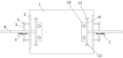
fig. 2 is a schematic sectional view of a front view of a transverse groove processing device for a drilling machine according to the present invention;
fig. 3 is a top view of a transverse groove processing device for a drilling machine according to the present invention;
fig. 4 is a side view of the cross slot processing device for the drilling machine provided by the utility model.
In the figure: 1. a base plate; 2. a vertical plate; 3. a rotating shaft; 4. a worm gear; 5. a gear; 6. a first bearing; 7. a worm; 8. a rack; 9. positioning a plate; 10. a transverse plate; 11. a threaded rod; 12. a rubber disc; 13. a fixed shaft; 14. a roller; 15. a groove; 16. a rectangular hole; 17. a limiting seat; 18. a circular hole; 19. a second bearing.
Detailed Description
The technical solutions in the embodiments of the present invention will be described clearly and completely with reference to the accompanying drawings in the embodiments of the present invention, and it is obvious that the described embodiments are only some embodiments of the present invention, not all embodiments.
Referring to fig. 1-4, this scheme provides one embodiment: the utility model provides a transverse groove processingequipment for drilling machine, comprising a base plate 1, the top side fixed welding of bottom plate 1 has riser 2 that two symmetries set up, the both sides of bottom plate 1 all rotate and are provided with pivot 3, fixed cover is equipped with worm wheel 4 and gear 5 in the pivot 3, 5 fixed welding of gear is at the rear side of worm wheel 4, the both sides of bottom plate 1 all rotate the worm 7 that are connected with the level setting, worm 7 meshes with corresponding worm wheel 4 mutually, it is provided with rack 8 all to slide on two riser 2, the equal fixed welding of the one end that two rack 8 are close to each other has locating plate 9, the equal fixed welding in one side that two locating plates 9 are close to each other has diaphragm 10, the top side threaded connection of diaphragm 10 has two threaded rods 11, the equal fixed mounting in bottom of four threaded rods 11 has rubber disc 12.
Referring to fig. 1, in this embodiment, the rotating shaft 3 is fixedly sleeved with the inner rings of the two first bearings 6, the outer ring of the first bearing 6 is fixedly welded with the supporting rod, and one end of the supporting rod, which is close to the threaded rod 11, is fixedly welded with the bottom plate 1, so that the rotating shaft 3 rotates more stably.
Referring to fig. 2, in this embodiment, a circular hole 18 is formed in one side of the bottom plate 1, one ends of the two worms 7, which are close to each other, are fixedly welded, a second bearing 19 is fixedly sleeved on each of the two worms 7, and an outer ring of the second bearing 19 is fixedly arranged on an inner wall of the circular hole 18, so that the two worms 7 rotate more stably.
Referring to fig. 2, in this embodiment, four screw holes have been seted up to the top side of diaphragm 10, all are equipped with a set of internal thread in four screw holes, all are equipped with a set of external screw thread on four threaded rods 11, and the external screw thread meshes with corresponding internal thread mutually, and the machined part is treated to the adjusting threaded rod 11 of being convenient for fixes a position.
Referring to fig. 3, in this embodiment, a fixed shaft 13 is fixedly welded to both the front side and the rear side of the positioning plate 9, a roller 14 is rotatably sleeved on the fixed shaft 13, and the roller 14 and the bottom plate 1 are arranged in a rolling manner, so as to reduce the friction force generated during the movement of the positioning plate 9.
Referring to fig. 4, in this embodiment, rectangular hole 16 has all been seted up on two risers 2, and fixed welding has two spacing seats 17 that the symmetry set up on the inner wall of rectangular hole 16, has seted up two recesses 15 on the rack 8, and spacing seat 17 slides and sets up in corresponding recess 15, plays the spacing effect of direction to rack 8.
The working principle is that when a transverse groove is needed to be machined, a workpiece to be machined is placed on the bottom plate 1 at first, a hand wheel is rotated, the rotation of the hand wheel drives the two worms 7 to rotate simultaneously, the worms 7 rotate to be meshed with the corresponding worm gears 4, the two worm gears 4 rotate in opposite directions, the gears 4 rotate to drive the gears 5 to rotate, the gears 5 are meshed with the corresponding racks 8 to enable the two racks 8 to be close to each other, the two positioning plates 9 are driven to move by the racks 8 to enable the two positioning plates 9 to be close to each other, when the two positioning plates 9 clamp and limit the workpiece to be machined, the hand wheel stops rotating, the four knobs rotate, the threaded rod 11 rotates, one side of the threaded rod 11 rotates and moves downwards slowly, when the workpiece to be machined is positioned by the rubber disc 12, the knobs stop rotating, stable clamping effect of the workpiece to be machined is achieved in a matched mode, the workpiece to be machined cannot deviate in machining, the machining effect is better, when the threaded rod is machined, the four knobs rotate in opposite directions, the threaded rod 11 relieves the positioning of the workpiece to be machined, the hand wheel rotates in opposite directions, the two positioning plates 9 are far away from each other, the workpiece to be taken out, and the workpiece to be machined is simple to operate.
The above, only be the embodiment of the preferred of the present invention, but the protection scope of the present invention is not limited thereto, and any person skilled in the art is in the technical scope of the present invention, according to the technical solution of the present invention and the utility model, which are designed to be replaced or changed equally, all should be covered within the protection scope of the present invention.
Claims (6)
1. The utility model provides a cross slot processingequipment for drilling machine, includes bottom plate (1), its characterized in that: the top side fixed welding of bottom plate (1) has riser (2) that two symmetries set up, the both sides of bottom plate (1) are all rotated and are provided with pivot (3), fixed cover is equipped with worm wheel (4) and gear (5) on pivot (3), gear (5) fixed welding is in the rear side of worm wheel (4), the both sides of bottom plate (1) are all rotated and are connected with worm (7) that the level set up, worm (7) and corresponding worm wheel (4) mesh mutually, two equal slip is provided with rack (8) on riser (2), two the equal fixed welding of one end that rack (8) are close to each other has locating plate (9), two the equal fixed welding in one side that locating plate (9) are close to each other has diaphragm (10), the top side threaded connection of diaphragm (10) has two threaded rod (11), four the equal fixed mounting in bottom of threaded rod (11) has rubber disc (12).
2. The transverse groove processing device for the drilling machine as claimed in claim 1, wherein: the fixed cover is equipped with the inner circle of two first bearings (6) in pivot (3), the fixed welding of outer lane of first bearing (6) has the bracing piece, the bracing piece is close to the one end of threaded rod (11) with bottom plate (1) fixed welding.
3. The transverse groove processing device for the drilling machine as claimed in claim 1, wherein: round hole (18) have been seted up to one side of bottom plate (1), two the one end fixed weld that worm (7) are close to each other, two all fixed cover is equipped with second bearing (19) on worm (7), the outer lane of second bearing (19) with the inner wall of round hole (18) is fixed to be set up.
4. The transverse groove processing device for the drilling machine as claimed in claim 1, wherein: the front side and the rear side of the positioning plate (9) are fixedly welded with a fixing shaft (13), the fixing shaft (13) is rotatably sleeved with a roller (14), and the roller (14) and the bottom plate (1) are arranged in a rolling mode.
5. The transverse groove processing device for the drilling machine as claimed in claim 1, wherein: two rectangular hole (16) have all been seted up on riser (2), fixed welding has spacing seat (17) that two symmetries set up on the inner wall of rectangular hole (16), two recesses (15) have been seted up on rack (8), spacing seat (17) slide to set up correspondingly in recess (15).
6. The transverse groove processing device for the drilling machine as claimed in claim 1, wherein: four threaded holes are formed in the top side of the transverse plate (10), a group of internal threads are arranged in the four threaded holes, a group of external threads are arranged on the four threaded rods (11), and the external threads are meshed with the corresponding internal threads.
Priority Applications (1)
| Application Number | Priority Date | Filing Date | Title |
|---|---|---|---|
| CN202221295370.9U CN217890229U (en) | 2022-05-26 | 2022-05-26 | Transverse groove machining device for drilling machine |
Applications Claiming Priority (1)
| Application Number | Priority Date | Filing Date | Title |
|---|---|---|---|
| CN202221295370.9U CN217890229U (en) | 2022-05-26 | 2022-05-26 | Transverse groove machining device for drilling machine |
Publications (1)
| Publication Number | Publication Date |
|---|---|
| CN217890229U true CN217890229U (en) | 2022-11-25 |
Family
ID=84112644
Family Applications (1)
| Application Number | Title | Priority Date | Filing Date |
|---|---|---|---|
| CN202221295370.9U Active CN217890229U (en) | 2022-05-26 | 2022-05-26 | Transverse groove machining device for drilling machine |
Country Status (1)
| Country | Link |
|---|---|
| CN (1) | CN217890229U (en) |
Cited By (1)
| Publication number | Priority date | Publication date | Assignee | Title |
|---|---|---|---|---|
| CN117984041A (en) * | 2024-03-22 | 2024-05-07 | 众智伟业智能科技(苏州)有限公司 | Fixing method and fixture for welding based on power electronic components |
-
2022
- 2022-05-26 CN CN202221295370.9U patent/CN217890229U/en active Active
Cited By (1)
| Publication number | Priority date | Publication date | Assignee | Title |
|---|---|---|---|---|
| CN117984041A (en) * | 2024-03-22 | 2024-05-07 | 众智伟业智能科技(苏州)有限公司 | Fixing method and fixture for welding based on power electronic components |
Similar Documents
| Publication | Publication Date | Title |
|---|---|---|
| CN217890229U (en) | Transverse groove machining device for drilling machine | |
| CN212664961U (en) | Drilling machine convenient to operate and used for machining steel pipes | |
| CN112692322A (en) | Special multi-head drill for drilling from inside to outside | |
| CN108145194A (en) | A kind of multiple degrees of freedom drilling machine | |
| CN216989935U (en) | Bench drill that possesses splashproof function | |
| CN210648598U (en) | Drilling machine | |
| CN116141030A (en) | Swing-head type five-axis cam rotary table machining machine tool and use method thereof | |
| CN214770278U (en) | Cabinet metal plate processing and cutting device | |
| CN116690263B (en) | Column type double-sided boring and milling machine | |
| CN213135793U (en) | Inclined lathe body double-spindle turning and milling composite machine tool | |
| CN215919341U (en) | Sprocket wire-electrode cutting processing strutting arrangement | |
| CN215468599U (en) | Tapping machine tool convenient for replacing workpiece | |
| CN112077606B (en) | Universal fixing support for drilling and milling | |
| CN213104558U (en) | Multi-station feeding type drilling machine | |
| US4162565A (en) | Press brake milling machine | |
| CN113909917A (en) | Bolt perforation, reaming and chamfering integrated device on flange plate | |
| CN203843227U (en) | Hole machining tool | |
| CN218396013U (en) | Drilling device for machining cylindrical shell-shaped workpiece by lathe | |
| CN219704136U (en) | Multi-station fixing support based on numerical control lathe and used for workpiece machining | |
| CN217018676U (en) | Hydraulic directional positioning multi-hole internal expansion type gang drill equipment for motor rotor | |
| CN218310991U (en) | Differential mechanism shell cross drilling bed | |
| CN221870389U (en) | Drilling device for workpiece machining | |
| CN214602085U (en) | Drilling machine | |
| CN210359383U (en) | Ball joint drilling machine | |
| CN212398868U (en) | Accurate five metals tool |
Legal Events
| Date | Code | Title | Description |
|---|---|---|---|
| GR01 | Patent grant | ||
| GR01 | Patent grant |