CN217855516U - Flat membrane module structure - Google Patents
Flat membrane module structure Download PDFInfo
- Publication number
- CN217855516U CN217855516U CN202221619430.8U CN202221619430U CN217855516U CN 217855516 U CN217855516 U CN 217855516U CN 202221619430 U CN202221619430 U CN 202221619430U CN 217855516 U CN217855516 U CN 217855516U
- Authority
- CN
- China
- Prior art keywords
- flange
- nut
- inner flange
- pressure
- outer flange
- Prior art date
- Legal status (The legal status is an assumption and is not a legal conclusion. Google has not performed a legal analysis and makes no representation as to the accuracy of the status listed.)
- Active
Links
Images
Landscapes
- Separation Using Semi-Permeable Membranes (AREA)
Abstract
A flat membrane module structure is provided with a central rod, a lower nut, a lower outer flange, a lower inner flange, a lower sealing ring, a pressed part, a fastening flange, an upper inner flange, an upper sealing ring, an upper outer flange, a sleeve, an upper nut and a pressure-bearing shell; the central rod sequentially penetrates through the lower nut, the lower outer flange, the lower inner flange, the pressed part, the fastening flange, the upper inner flange and the upper outer flange from bottom to top; the lower sealing ring is filled between the pressure-bearing shell and the lower inner flange; the upper sealing ring is filled between the pressure-bearing shell and the upper inner flange; the lower end of the sleeve is positioned in the mounting opening of the fastening flange, and the upper end of the sleeve penetrates through the lower inner flange and is exposed out of the lower outer flange; the upper end of the central rod passes through the fastening flange and then is exposed out of the upper end of the sleeve, and the upper nut is connected to the top end of the central rod; the lower inner flange, the lower sealing ring, the pressure-bearing component, the fastening flange, the upper inner flange and the upper sealing ring are positioned in the pressure-bearing shell. The utility model discloses simple to operate avoids repeated reversal, and is safe secure.
Description
Technical Field
The utility model belongs to the technical field of water treatment, concretely relates to dull and stereotyped membrane module structure.
Background
At present, traditional dull and stereotyped membrane module because structural design's problem, in the installation, need repeated installation of reversing, the complicated pipeline in bottom can't be avoided, and the installation location is more, and the fastening is inconvenient, leads to the installation inconvenient, and processing materials is big, and the processing cost is high. In addition, the weight of the flat membrane module exceeds 180Kg, and the repeated creeping of the internal components of the membrane module, the deformation or the displacement of the components can be caused by carrying the flat membrane module back and forth or repeated upside-down installation; if the operation is improper in the subsequent hoisting process, the safety of personnel can be threatened. How to provide a simple to operate, avoid repeated reversal, safe guaranteed flat membrane module has realistic meaning.
SUMMERY OF THE UTILITY MODEL
The utility model discloses not enough to prior art exists provides a dull and stereotyped membrane module structure, and solution traditional scheme installation process needs to be repeated and reverses, and the installation is inconvenient, and has the problem of follow-up potential safety hazard.
The utility model provides an above-mentioned technical problem's technical scheme as follows: a flat membrane component structure comprises a central rod, a lower nut, a lower outer flange, a lower inner flange, a lower sealing ring, a pressed part, a fastening flange, an upper inner flange, an upper sealing ring, an upper outer flange, a sleeve, an upper nut and a pressure-bearing shell;
the central rod sequentially penetrates through the lower nut, the lower outer flange, the lower inner flange, the pressed part, the fastening flange, the upper inner flange and the upper outer flange from bottom to top;
the lower sealing ring is filled between the pressure-bearing shell and the lower inner flange; the upper sealing ring is filled between the pressure-bearing shell and the upper inner flange; the lower end of the sleeve is positioned in the mounting opening of the fastening flange, and the upper end of the sleeve penetrates through the lower inner flange and is exposed out of the lower outer flange;
the upper end of the central rod penetrates through the fastening flange and then is exposed out of the upper end of the sleeve, and the upper nut is connected to the top end of the central rod;
the lower inner flange, the lower sealing ring, the pressed part, the fastening flange, the upper inner flange and the upper sealing ring are positioned in the pressure-bearing shell.
As a preferable scheme of the structure of the flat membrane assembly, the flat membrane assembly further comprises an auxiliary pull rod, the auxiliary pull rod is connected between the lower outer flange and the upper outer flange, a lower auxiliary nut is connected to the lower portion of the lower outer flange of the auxiliary pull rod, and an upper auxiliary nut is connected to the upper portion of the upper outer flange of the auxiliary pull rod.
As a preferable scheme of the structure of the flat membrane module, an upper gasket is filled between the upper nut and the sleeve; and a lower gasket is filled between the lower nut and the lower outer flange.
As a preferable scheme of the structure of the flat membrane component, the pressure-bearing part comprises a flow guide disc, and membranes are distributed on the flow guide disc.
As a preferable scheme of the structure of the flat membrane module, the lower outer flange is connected with a water inlet joint, and a water flow channel is formed between the pressure-bearing component and the pressure-bearing shell;
the water inlet joint is communicated with the water flow channel through the lower inner flange.
As the optimal scheme of the structure of the flat membrane component, the fastening flange is provided with a water guide opening, and the water flow channel is communicated with the pressed part through the water guide opening.
As a preferable scheme of the structure of the flat membrane module, the lower outer flange is connected with a water outlet connector, and the water outlet connector is communicated with a concentrated water inlet positioned below the pressure part.
As a preferable scheme of the structure of the flat membrane module, a purified water inlet is distributed on the side part of the central rod, a purified water outlet is arranged at the bottom of the central rod, and the purified water inlet is communicated with the purified water outlet.
The utility model is provided with a central rod, a lower nut, a lower outer flange, a lower inner flange, a lower sealing ring, a pressed part, a fastening flange, an upper inner flange, an upper sealing ring, an upper outer flange, a sleeve, an upper nut and a pressure-bearing shell; the central rod sequentially penetrates through the lower nut, the lower outer flange, the lower inner flange, the pressed part, the fastening flange, the upper inner flange and the upper outer flange from bottom to top; the lower sealing ring is filled between the pressure-bearing shell and the lower inner flange; the upper sealing ring is filled between the pressure-bearing shell and the upper inner flange; the lower end of the sleeve is positioned in the mounting opening of the fastening flange, and the upper end of the sleeve penetrates through the lower inner flange and is exposed out of the lower outer flange; the upper end of the central rod passes through the fastening flange and then is exposed out of the upper end of the sleeve, and the upper nut is connected to the top end of the central rod; the lower inner flange, the lower sealing ring, the compression part, the fastening flange, the upper inner flange and the upper sealing ring are positioned in the pressure-bearing shell. The utility model changes the structure form of the flat membrane component, can be installed from bottom to top, and solves the problem of difficult installation of the flat membrane component during installation and later maintenance; the membrane module has the advantages of less processing materials, low processing cost, less installation and positioning, better carrying and easier maintenance; the accessible becomes flexible top part, realizes from last dismouting down, avoids the repetition of on-the-spot direction to reverse, reduces artifical and relevant corollary equipment's live time, obtains effectively guaranteeing in the aspect of safety.
Drawings
In order to more clearly illustrate the embodiments of the present invention or the technical solutions in the prior art, the drawings used in the description of the embodiments or the prior art will be briefly described below. It should be apparent that the drawings in the following description are merely exemplary, and that other embodiments can be derived from the drawings provided by those of ordinary skill in the art without inventive effort.
The structure, ratio, size and the like shown in the present specification are only used for matching with the content disclosed in the specification, so as to be known and read by people familiar with the technology, and are not used for limiting the limit conditions which can be implemented by the present invention, so that the present invention has no technical essential significance, and any structure modification, ratio relationship change or size adjustment should still fall within the scope which can be covered by the technical content disclosed by the present invention without affecting the efficacy and the achievable purpose of the present invention.
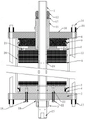
Fig. 1 is a schematic structural view of a flat membrane module provided in an embodiment of the present invention.
In the figure, 1, a center rod; 2. a lower nut; 3. a lower outer flange; 4. a lower inner flange; 5. a lower seal ring; 6. a pressure receiving member; 7. fastening a flange; 8. an upper inner flange; 9. an upper sealing ring; 10. an upper outer flange; 11. a sleeve; 12. screwing a nut; 13. a pressure-bearing housing; 14. an auxiliary pull rod; 15. a lower auxiliary nut; 16. an upper auxiliary nut; 17. an upper gasket; 18. a lower gasket; 19. a water inlet joint; 20. a water flow channel; 21. a water guide port; 22. a water outlet joint; 23. a concentrated water introduction port; 24. a purified water introduction port; 25. and (5) outputting the purified water.
Detailed Description
In order to make the above objects, features and advantages of the present invention more comprehensible, embodiments of the present invention are described in detail below with reference to the accompanying drawings. In the following description, numerous specific details are set forth in order to provide a thorough understanding of the present invention. The invention may be embodied in many other forms different from those described herein and similar modifications may be made by those skilled in the art without departing from the spirit and scope of the invention and, therefore, the invention is not to be limited to the specific embodiments disclosed below.
Unless defined otherwise, all technical and scientific terms used herein have the same meaning as commonly understood by one of ordinary skill in the art to which this invention belongs. The terminology used herein in the description of the invention is for the purpose of describing particular embodiments only and is not intended to be limiting of the invention. As used herein, the term "and/or" includes any and all combinations of one or more of the associated listed items.
Referring to fig. 1, an embodiment of the present invention provides a flat membrane module structure, including a central rod 1, a lower nut 2, a lower outer flange 3, a lower inner flange 4, a lower sealing ring 5, a pressed part 6, a fastening flange 7, an upper inner flange 8, an upper sealing ring 9, an upper outer flange 10, a sleeve 11, an upper nut 12, and a pressure-bearing housing 13;
the central rod 1 sequentially penetrates through the lower nut 2, the lower outer flange 3, the lower inner flange 4, the compression part 6, the fastening flange 7, the upper inner flange 8 and the upper outer flange 10 from bottom to top;
the lower sealing ring 5 is filled between the pressure-bearing outer shell 13 and the lower inner flange 4; the upper sealing ring 9 is filled between the pressure-bearing outer shell 13 and the upper inner flange 8; the lower end of the sleeve 11 is positioned in the mounting opening of the fastening flange 7, and the upper end of the sleeve 11 passes through the lower inner flange 4 and is exposed out of the lower outer flange 3;
the upper end of the central rod 1 passes through the fastening flange 7 and then is exposed out of the upper end of the sleeve 11, and the upper nut 12 is connected to the top end of the central rod 1;
the lower inner flange 4, the lower seal ring 5, the pressure receiving member 6, the fastening flange 7, the upper inner flange 8, and the upper seal ring 9 are located inside the pressure-receiving housing 13.
In this embodiment, the flange structure further comprises an auxiliary pull rod 14, the auxiliary pull rod 14 is connected between the lower outer flange 3 and the upper outer flange 10, a lower auxiliary nut 15 is connected to the lower portion of the lower outer flange 3 of the auxiliary pull rod 14, and an upper auxiliary nut 16 is connected to the upper portion of the upper outer flange 10 of the auxiliary pull rod 14. An upper gasket 17 is filled between the upper nut 12 and the sleeve 11; a lower gasket 18 is filled between the lower nut 2 and the lower outer flange 3.
Specifically, the lower outer flange 3 and the upper outer flange 10 are fastened through the auxiliary pull rod 14, the upper auxiliary nut 16 and the lower auxiliary nut 15, the upper nut 12 and the upper gasket 17 are matched to fasten the sleeve 11, the lower nut 2 and the lower gasket 18 are matched to fasten the lower outer flange 3, and the fastened upper auxiliary nut 16, the lower auxiliary nut 15, the upper nut 12 and the lower nut 2 have a fixing effect on the whole flat membrane module. Meanwhile, the upper gasket 17 can increase the contact area between the upper nut 12 and the sleeve 11, and the lower gasket 18 can increase the contact area between the lower nut 2 and the lower outer flange 3, so that the pressure is reduced, and the looseness is prevented.
In this embodiment, the compression part 6 includes a diversion disc, and a membrane is distributed on the diversion disc. The lower outer flange 3 is connected with a water inlet joint 19, and a water flow channel 20 is formed between the pressure-bearing part 6 and the pressure-bearing shell 13; the water inlet joint 19 is communicated with the water flow channel 20 through the lower inner flange 4. The fastening flange 7 is provided with a water guide opening 21, and the water flow channel 20 is communicated with the pressure receiving part 6 through the water guide opening 21. The lower outer flange 3 is connected with a water outlet joint 22, and the water outlet joint 22 is communicated with a concentrated water inlet 23 below the pressure part 6. The lateral part of the central rod 1 is distributed with a purified water inlet 24, the bottom of the central rod 1 is provided with a purified water outlet 25, and the purified water inlet 24 is communicated with the purified water outlet 25.
Specifically, the pressed part 6 per se is in the prior art, and plays a role in purifying water flow through the superposition and matching of the flow guide disc and the membrane. The water flow introduced from the water inlet joint 19 enters the water flow passage 20 through the lower inner flange 4, is introduced into the pressure receiving part 6 through the water guide port 21 for purification due to the sealing action of the upper seal ring 9 and the lower seal ring 5, and is discharged from the purified water outlet 25 through the purified water introduction port 24. The concentrated water enters the concentrated water inlet 23 and is discharged from the water outlet joint 22.
The utility model discloses a follow ascending installation as follows from down:
the central rod 1 is used as a guide rod, all parts are sequentially installed from bottom to top, the lower nut 2 and the lower gasket 18 are matched and screwed on the central rod 1 through threads, the lower outer flange 3, the lower inner flange 4 and the lower sealing ring 5 are fixed upwards, the water outlet joint 22 and the water inlet joint 19 are fixed after aligning to hole sites of the lower outer flange 3 and the lower inner flange 4, and positioning and pipeline connection are carried out; the upside is established ties and is pressed part 6, and the fastening inner flange is laid at the top after the installation, lays sleeve 11 in proper order, goes up gasket 17, upper nut 12 fastens, then installs inner flange 8 and upper seal ring 9, installs pressure-bearing shell 13 again, and outer flange 10 is installed at the top after the installation is accomplished, carries out system's fastening and fixing through auxiliary pull rod 14, last auxiliary nut 16 and lower auxiliary nut 15, carries out inside fluid seal through upper seal ring 9 and lower seal ring 5.
To sum up, the utility model is provided with a central rod 1, a lower nut 2, a lower outer flange 3, a lower inner flange 4, a lower sealing ring 5, a pressed part 6, a fastening flange 7, an upper inner flange 8, an upper sealing ring 9, an upper outer flange 10, a sleeve 11, an upper nut 12 and a pressed shell 13; the central rod 1 sequentially penetrates through a lower nut 2, a lower outer flange 3, a lower inner flange 4, a pressed part 6, a fastening flange 7, an upper inner flange 8 and an upper outer flange 10 from bottom to top; the lower sealing ring 5 is filled between the pressure-bearing shell 13 and the lower inner flange 4; the upper sealing ring 9 is filled between the pressure-bearing shell 13 and the upper inner flange 8; the lower end of the sleeve 11 is positioned in the mounting opening of the fastening flange 7, and the upper end of the sleeve 11 penetrates through the lower inner flange 4 and is exposed out of the lower outer flange 3; the upper end of the central rod 1 passes through the fastening flange 7 and then is exposed out of the upper end of the sleeve 11, and the upper nut 12 is connected to the top end of the central rod 1; the lower inner flange 4, the lower sealing ring 5, the pressure-bearing part 6, the fastening flange 7, the upper inner flange 8 and the upper sealing ring 9 are positioned inside the pressure-bearing shell 13. The utility model changes the structure form of the flat membrane component, and solves the problem of difficult installation of the flat membrane component during installation and later maintenance; the membrane component has the advantages of less processing materials, low processing cost, less installation and positioning, better carrying and easier maintenance, can be locked by the upper nut 12 in the maintenance process, is convenient for personnel to fasten at the top, and avoids a pipeline with complicated bottom; the accessible becomes flexible top part, realizes from last dismouting down, avoids the repetition of on-the-spot direction to reverse, reduces artifical and relevant corollary equipment's live time, obtains effectively guaranteeing in the aspect of safety.
The technical features of the embodiments described above may be arbitrarily combined, and for the sake of brevity, all possible combinations of the technical features in the embodiments described above are not described, but should be considered as being within the scope of the present specification as long as there is no contradiction between the combinations of the technical features.
The above-mentioned embodiments only represent some embodiments of the present invention, and the description thereof is specific and detailed, but not to be construed as limiting the scope of the present invention. It should be noted that, for those skilled in the art, without departing from the concept of the present invention, several variations and modifications can be made, which all fall within the scope of the present invention. Therefore, the protection scope of the present invention should be subject to the appended claims.
Claims (8)
1. A flat membrane module structure is characterized by comprising a central rod (1), a lower nut (2), a lower outer flange (3), a lower inner flange (4), a lower sealing ring (5), a pressed part (6), a fastening flange (7), an upper inner flange (8), an upper sealing ring (9), an upper outer flange (10), a sleeve (11), an upper nut (12) and a pressure-bearing shell (13);
the central rod (1) sequentially penetrates through the lower nut (2), the lower outer flange (3), the lower inner flange (4), the pressed part (6), the fastening flange (7), the upper inner flange (8) and the upper outer flange (10) from bottom to top;
the lower sealing ring (5) is filled between the pressure-bearing shell (13) and the lower inner flange (4); the upper sealing ring (9) is filled between the pressure-bearing shell (13) and the upper inner flange (8); the lower end of the sleeve (11) is positioned in a mounting opening of the fastening flange (7), and the upper end of the sleeve (11) penetrates through the lower inner flange (4) and is exposed out of the lower outer flange (3);
the upper end of the central rod (1) penetrates through the fastening flange (7) and then is exposed out of the upper end of the sleeve (11), and the upper nut (12) is connected to the top end of the central rod (1);
the lower inner flange (4), the lower sealing ring (5), the pressure-bearing part (6), the fastening flange (7), the upper inner flange (8) and the upper sealing ring (9) are positioned inside the pressure-bearing shell (13).
2. The flat membrane module structure according to claim 1, further comprising an auxiliary pull rod (14), wherein the auxiliary pull rod (14) is connected between the lower outer flange (3) and the upper outer flange (10), the auxiliary pull rod (14) is connected with a lower auxiliary nut (15) at the lower part of the lower outer flange (3), and the auxiliary pull rod (14) is connected with an upper auxiliary nut (16) at the upper part of the upper outer flange (10).
3. A flat sheet membrane module structure according to claim 1, wherein an upper spacer (17) is filled between said upper nut (12) and said sleeve (11); and a lower gasket (18) is filled between the lower nut (2) and the lower outer flange (3).
4. A flat sheet membrane module structure according to claim 1, wherein the pressure receiving member (6) comprises a flow guiding disc, and the flow guiding disc is distributed with membrane sheets.
5. A flat-sheet membrane module structure according to claim 1, wherein a water inlet connector (19) is connected to the lower outer flange (3), and a water flow passage (20) is formed between the pressure receiving member (6) and the pressure-receiving housing (13);
the water inlet joint (19) is communicated with the water flow channel (20) through the lower inner flange (4).
6. A flat-sheet membrane module structure according to claim 5, wherein said fastening flange (7) is provided with a water guiding opening (21), and said water flow channel (20) leads said pressure receiving member (6) through said water guiding opening (21).
7. A flat-sheet membrane module structure according to claim 6, wherein the lower outer flange (3) is connected with a water outlet connector (22), and the water outlet connector (22) is communicated with a concentrated water inlet (23) below the pressure receiving part (6).
8. The flat sheet membrane module structure according to claim 7, wherein the side of the central rod (1) is distributed with purified water inlet ports (24), the bottom of the central rod (1) is provided with purified water outlet ports (25), and the purified water inlet ports (24) are communicated with the purified water outlet ports (25).
Priority Applications (1)
| Application Number | Priority Date | Filing Date | Title |
|---|---|---|---|
| CN202221619430.8U CN217855516U (en) | 2022-06-27 | 2022-06-27 | Flat membrane module structure |
Applications Claiming Priority (1)
| Application Number | Priority Date | Filing Date | Title |
|---|---|---|---|
| CN202221619430.8U CN217855516U (en) | 2022-06-27 | 2022-06-27 | Flat membrane module structure |
Publications (1)
| Publication Number | Publication Date |
|---|---|
| CN217855516U true CN217855516U (en) | 2022-11-22 |
Family
ID=84098421
Family Applications (1)
| Application Number | Title | Priority Date | Filing Date |
|---|---|---|---|
| CN202221619430.8U Active CN217855516U (en) | 2022-06-27 | 2022-06-27 | Flat membrane module structure |
Country Status (1)
| Country | Link |
|---|---|
| CN (1) | CN217855516U (en) |
-
2022
- 2022-06-27 CN CN202221619430.8U patent/CN217855516U/en active Active
Similar Documents
| Publication | Publication Date | Title |
|---|---|---|
| CN217855516U (en) | Flat membrane module structure | |
| WO2012055092A1 (en) | Combination unit and combination method of multiple membrane shells | |
| CN207552020U (en) | A kind of film degasser in pharmacy purifying water treatment system | |
| CN208406643U (en) | Hyperfiltration membrane assembly | |
| CN201147675Y (en) | Water purifier | |
| CN201537422U (en) | Stainless steel straight-through filter with pressure detecting device | |
| CN211141671U (en) | Rubber plate type microporous aerator | |
| CN208687207U (en) | A kind of universal water pipe joint assembly and drive motor controller | |
| CN209828733U (en) | Membrane core connecting piece, sanitary membrane filtration assembly and membrane separation device | |
| CN209501371U (en) | A kind of reverse osmosis water quality purifying equipment convenient for cleaning | |
| CN208858631U (en) | A kind of sealing structure of vertical multiple-stage conduit centrifugal pump | |
| CN218582534U (en) | Environment-friendly low-pressure pump input shaft flange | |
| CN217092433U (en) | Filter | |
| CN212127627U (en) | Efficient filtering device of reverse osmosis equipment | |
| CN218741291U (en) | Pipeline backflow structure of reverse osmosis equipment | |
| CN213018277U (en) | Inner tank and outer tank communicating device for sewage treatment | |
| CN212669285U (en) | Reverse osmosis equipment of pharmaceutical factory | |
| CN212616605U (en) | Drinking water monitoring and purifying device | |
| CN214233535U (en) | Novel disc ultra-high pressure resistant membrane column | |
| CN215654197U (en) | Large-flux pollution discharge pre-filter | |
| CN2573064Y (en) | Capillary ultrafilter membrane assembly | |
| CN104128095B (en) | A kind of high resistant to pollution hollow fiber film assembly | |
| CN216604774U (en) | Reverse osmosis membrane medical water purification device | |
| CN213049594U (en) | Sewage plant tap water inlet pipe with water loss calculation device | |
| CN216472375U (en) | Intelligent self-adaptation column type membrane module |
Legal Events
| Date | Code | Title | Description |
|---|---|---|---|
| GR01 | Patent grant | ||
| GR01 | Patent grant |