CN217855326U - Waste gas purification device - Google Patents
Waste gas purification device Download PDFInfo
- Publication number
- CN217855326U CN217855326U CN202222242941.9U CN202222242941U CN217855326U CN 217855326 U CN217855326 U CN 217855326U CN 202222242941 U CN202222242941 U CN 202222242941U CN 217855326 U CN217855326 U CN 217855326U
- Authority
- CN
- China
- Prior art keywords
- box body
- box
- brush
- exhaust gas
- filter plate
- Prior art date
- Legal status (The legal status is an assumption and is not a legal conclusion. Google has not performed a legal analysis and makes no representation as to the accuracy of the status listed.)
- Active
Links
Images


Abstract
The utility model belongs to the technical field of exhaust-gas purification, concretely relates to exhaust-gas purification device, including the box, the box is equipped with the spray tube, and the spray tube is equipped with the atomizer, and the box is equipped with the water tank, and the box is equipped with the water pump, and the box is equipped with the filter, and the box is equipped with cleans the mechanism, and the box is equipped with the intake pipe, and the box is equipped with the outlet duct, and the intake pipe is equipped with first solenoid valve; the cleaning mechanism comprises a boss, a sliding groove is formed in the boss, a screw rod is arranged in the sliding groove and provided with a first sliding block, a brush is arranged on the first sliding block, a motor is arranged in the box body, a liquid outlet is formed in the box body, and a second electromagnetic valve is arranged at the liquid outlet; the utility model discloses set up atomizer and filter and clear away the particulate matter, can carry out more thorough processing to the particulate matter that produces in the balloon production process, set up the brush simultaneously and clear up the filter lower extreme, keep the cleanness of filter in order to keep its filtration efficiency to the particulate matter.
Description
Technical Field
The utility model belongs to the technical field of exhaust purification, concretely relates to exhaust gas purification device.
Background
Most balloons are all made by latex, later wrap up pigment mixture among the latex, just can make the balloon of different colors, and latex can produce the waste gas of many pungent smells in process of production, including various pollutants such as big particulate matter, sulfur dioxide, nitrogen dioxide, when handling the particulate matter in the latex waste gas at present, adopt dry-type processing usually, the effect of cleaing away the particulate matter is perfect inadequately, lead to easily purifying incomplete waste gas and discharge in the air, cause the pollution to the air, influence near people's life.
SUMMERY OF THE UTILITY MODEL
The utility model aims at: aims at providing an exhaust gas purification device, has set up atomizer and filter and has clear away the particulate matter, can carry out more thorough processing to the particulate matter that produces in the balloon production process, can in time clear up the particulate matter of gathering together on the dust removal filter plate simultaneously, guarantees that the device clears away the effect of particulate matter in the waste gas.
In order to realize the technical purpose, the utility model adopts the following technical scheme:
the lower part of the outer side wall of the box body is provided with an air inlet pipe, the air inlet pipe is provided with a first electromagnetic valve, the upper part of the outer side wall of the box body is provided with an air outlet pipe, the other end of the air outlet pipe is connected with a purification tower, the right end of the purification tower is provided with an air outlet, the left side and the right side of the interior of the box body are symmetrically provided with spray pipes, the opposite sides of the two spray pipes are uniformly provided with a plurality of atomization nozzles, the upper end of the outer part of the box body is provided with a water tank, the upper end of the outer part of the box body is provided with a water pump, the water inlet of the water pump is connected with the water tank through a short pipe, the water outlet of the water pump is connected with the two spray pipes through a water pipe, a filter plate is detachably arranged in the middle part of the box body, and the middle part of the box body is provided with a cleaning mechanism matched with the filter plate;
the cleaning mechanism comprises a boss, the boss is fixedly arranged on the inner rear side wall of the box body, a sliding groove is formed in the boss, a screw rod is arranged in the sliding groove in a rotating mode, the screw rod is connected with a first sliding block matched with the sliding groove in a threaded mode, the first sliding block extends out of one side of the sliding groove and is provided with a brush plate, a brush is arranged at the upper end of the brush plate and is abutted to the lower end of the filter plate, a motor is fixedly arranged on the outer side wall of the box body, an output shaft of the motor penetrates through the box body and is connected with the screw rod in a transmission mode, the lower end of the box body is conical, a liquid outlet is formed in the conical bottom of the box body, and a second electromagnetic valve is arranged on the liquid outlet.
The side wall is fixed and is equipped with the slide rail before the box is inside, the slide rail is fixed and is equipped with the round bar, the round bar slides be equipped with the second slider that the slide rail matches, the second slider stretches out slide rail one side with brush board fixed connection.
The lower end of the box body is provided with four supporting legs, and the four supporting legs are provided with non-slip mats.
The inside lower extreme of purification tower is equipped with the drying plate, the drying plate top is equipped with the active carbon adsorption board.
And the air outlet is provided with an air pump.
The novel multifunctional cabinet is characterized in that a U-shaped lug is arranged inside the cabinet body, a U-shaped groove matched with the filter plate is formed in the U-shaped lug, a sealing ring is arranged on the front side of the U-shaped groove, a cabinet door is formed in the front end of the cabinet body, a sealing gasket is arranged on the inner side of the cabinet door (), and the cabinet door is abutted to the front end of the filter plate.
The utility model discloses set up atomizer and filter and clear away the particulate matter, can carry out more thorough processing to the particulate matter that produces in the balloon production process, set up the brush simultaneously and clear up the filter lower extreme, keep the cleanness of filter in order to keep its filtration efficiency to the particulate matter.
Drawings
The invention can be further illustrated by means of non-limiting examples given in the figures.
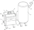
Fig. 1 is a schematic structural diagram of a first embodiment of an exhaust gas purification apparatus according to the present invention;
FIG. 2 is a first schematic sectional view of the structure of the tank, the water pump, the water tank, etc. of the present invention;
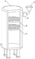
FIG. 3 is a schematic sectional view of the purification tower of the present invention;
FIG. 4 is a schematic sectional view of the structure of the tank, the water pump, the water tank, etc. of the present invention;
FIG. 5 is a schematic view of the structure at A in FIG. 4;
fig. 6 is a schematic structural view of the brush, the first slider and the second slider.
The main element symbols are as follows:
the device comprises a box body 1, an air inlet pipe 2, a first electromagnetic valve 3, an air outlet pipe 4, a purification tower 5, an air outlet 6, a spray pipe 7, an atomization nozzle 8, a water tank 9, a water pump 10, a filter plate 11, a boss 101, a sliding groove 102, a screw 103, a first sliding block 104, a brush plate 105, a brush 106, a motor 107, a liquid outlet 108, a second electromagnetic valve 109, a sliding rail 21, a round rod 22, a second sliding block 23, a supporting leg 31, an anti-skid pad 32, a drying plate 41, an activated carbon adsorption plate 42, an air outlet 43, an air suction pump 51, a U-shaped convex block 61, a U-shaped groove 62 and a box door 63.
Detailed Description
In order to make the present invention better understood by those skilled in the art, the technical solutions of the present invention are further described below with reference to the accompanying drawings and examples.
The first embodiment is as follows:
as shown in fig. 1-6, the utility model discloses a waste gas purifying device, including box 1, the lower part of the outer side wall of box 1 is provided with an air inlet pipe 2, air inlet pipe 2 is provided with a first solenoid valve 3, the upper part of the outer side wall of box 1 is provided with an air outlet pipe 4, the other end of air outlet pipe 4 is connected with a purifying tower 5, the right end of purifying tower 5 is provided with an air outlet 6, the left and right sides inside box 1 are symmetrically provided with spray pipes 7, the opposite sides of two spray pipes 7 are both provided with a plurality of atomizing spray heads 8, the upper end outside box 1 is provided with a water tank 9, the upper end outside box 1 is provided with a water pump 10, the water inlet of water pump 10 is connected with water tank 9 through a short pipe, the water outlet of water pump 10 is connected with two spray pipes 7 through a water pipe, the middle part inside box 1 is detachably provided with a filter plate 11, the middle part of box 1 is provided with a cleaning mechanism matched with filter plate 11;
the cleaning mechanism comprises a boss 101, the boss 101 is fixedly arranged on the inner rear side wall of the box body 1, a sliding groove 102 is formed in the boss 101, a screw 103 is rotatably arranged in the sliding groove 102, the screw 103 is in threaded connection with a first sliding block 104 matched with the sliding groove 102, a brush plate 105 is arranged on one side, extending out of the sliding groove 102, of the first sliding block 104, a brush 106 is arranged at the upper end of the brush plate 105, the brush 106 is abutted to the lower end of the filter plate 10, a motor 107 is fixedly arranged on the outer side wall of the box body 1, an output shaft of the motor 107 penetrates through the box body 1 and is in transmission connection with the screw 103, the lower end of the box body 1 is conical, a liquid outlet 108 is formed in the conical bottom of the box body 1, and the liquid outlet 108 is provided with a second electromagnetic valve 109;
in the initial state, the two electromagnetic valves are both in a closed state, the brush board 105 is positioned at the leftmost end of the filter board 11, when the device is used, the first electromagnetic valve 3 is opened, waste gas generated by balloon production is connected into the air inlet pipe 4, the water pump 10 is started, the waste gas enters the box body 1 and then flows upwards, the water in the water tank 4 is pumped out by the water pump 10, the water is conveyed to the two oppositely arranged spray pipes 7 through the water pipe and is sprayed out by the uniformly distributed atomizing spray heads 8, the water is sprayed to the waste gas and is contacted with particulate matters in the waste gas to take most of the particulate matters away from the waste gas, the treated waste gas continuously flows upwards, when passing through the filter board 11, the filter board 11 further filters the particulate matters in the waste gas, the waste gas after twice particulate matters filtration is discharged from the air outlet pipe 4, and when the particulate matters in the waste gas are filtered, some particulate matters are adhered to the lower end of the filter plate 11, so that the lower end of the filter plate 11 needs to be cleaned, the motor 107 is turned on, the motor 107 rotates forward to drive the screw 103 to rotate forward, the first slide block 104 slides rightwards along the chute 102 along with the rotation of the screw 103, the first slide block 104 drives the brush 106 to clean the lower end of the filter plate 11 from left to right, when the brush plate 105 moves to the rightmost end of the filter plate 11, the motor 107 rotates reversely to drive the screw 103 to rotate reversely, the first slide block 104 slides leftwards along the chute 102 along with the rotation of the screw 103, the first slide block 104 drives the brush 106 to clean the lower end of the filter plate 10 from right to left, the reciprocating is complete cleaning, the purified exhaust gas enters the purification tower 5 from the gas outlet pipe 4, and the exhaust gas purified by the gas outlet 6 of the purification tower 5 is discharged into the air; the waste water with the particles and the particles cleaned from the filter plate 11 fall into the conical bottom of the box body 1, and when the waste water needs to be cleaned, the second electromagnetic valve 109 is opened to discharge the waste water from the liquid outlet 108; the device can purify the particulate matters in the waste gas twice, remove the particulate matters in the waste gas more thoroughly, and clean the lower surface of the filter plate 11, so that the filter holes of the filter plate 10 are prevented from being blocked, and the filtering effect of the filter plate 11 is ensured;
the utility model discloses set up atomizer 7 and filter 10 and clear away the particulate matter, can carry out more thorough processing to the particulate matter that produces in the balloon production process, set up brush 106 simultaneously and clear up the filter lower extreme, keep the cleanness of filter 10 in order to keep its filtration efficiency to the particulate matter.
The left and the right inside the box body 1; a sliding rail 21 is fixedly arranged between the side walls, a round rod 22 is fixedly arranged on the sliding rail 21, a second sliding block 23 matched with the sliding rail 21 is arranged on the round rod 22 in a sliding mode, and the second sliding block 23 extends out of one side of the sliding rail 21 and is fixedly connected with the brush plate 105;
when the first sliding block 104 drives the brush plate 105 to move left and right, the second sliding block 23 slides left and right along the sliding rail 21, so that the moving stability of the brush plate 105 is increased.
The lower end of the box body 1 is provided with four supporting legs 31, and the four supporting legs 31 are provided with anti-skid pads 32;
supporting legs 31 through four evenly distributed support box 1 like this, can make box 1 more stable, and slipmat 32 can further increase stability for the device is difficult for sliding.
A U-shaped lug 61 is arranged in the box body 1, the U-shaped lug 61 is provided with a U-shaped groove 62 matched with the filter plate 11, the front side of the U-shaped groove 62 is provided with a sealing ring, the front end of the box body 1 is provided with a box door 63, the inner side of the box door (63) is provided with a sealing gasket, and the box door 63 is abutted against the front end of the filter plate 11;
although the brush 106 can clean the filter plate 11, the filter plate 11 is often replaced after being used for a period of time to keep the effect of removing particles of the device, when the filter plate 11 needs to be replaced, the box door 63 is opened, the old filter plate 11 is pulled out from the U-shaped groove 62, the front end of the new filter plate 11 is aligned with the opening at the front end of the U-shaped groove 62, the filter plate 11 is pushed into the rear end of the box door 62 and clamped into the rear end of the U-shaped groove 62, and the box door 63 is closed, so that the sealing ring and the sealing gasket can prevent exhaust gas from leaking out of the gap and affecting the overall purification effect; this setting makes the staff can conveniently change filter 11, can not influence the purification efficiency of device to waste gas because of the old and old of filter 11, easy operation, convenient and fast.
The second embodiment:
as shown in fig. 1-3, as a modification of the previous embodiment, a drying plate 41 is disposed at the lower end inside the purification tower 5, an activated carbon adsorption plate 42 is disposed above the drying plate 41, and an air outlet 43 is disposed at the right side of the purification tower 5;
the exhaust gas entering the purification tower 5 first passes through the drying plate 41, the drying plate 41 adsorbs water vapor in the exhaust gas, the dried exhaust gas passes through the activated carbon adsorption plate 42, and the activated carbon adsorption plate 42 can perform dry desulfurization on the exhaust gas, SO that SO in the exhaust gas is removed 2 The ammonia sulfate or sulfuric acid is generated by conversion, so that the desulfurization has the advantages of simple process and low energy consumption, and the treated waste gas is discharged into the air from the air outlet 6.
The air outlet 6 is provided with an air pump 51;
the air pump 51 can make the exhaust gas flow rapidly in a certain direction, thereby increasing the efficiency of the exhaust gas treatment.
The above embodiments are merely illustrative of the principles and effects of the present invention, and are not to be construed as limiting the invention. Modifications and variations can be made to the above-described embodiments by those skilled in the art without departing from the spirit and scope of the present invention. Accordingly, it is intended that all equivalent modifications or changes which may be made by those skilled in the art without departing from the spirit and technical spirit of the present invention shall be covered by the claims of the present invention.
Claims (6)
1. An exhaust gas purification device, includes the box, its characterized in that: the lower part of the outer side wall of the box body is provided with an air inlet pipe, the air inlet pipe is provided with a first electromagnetic valve, the upper part of the outer side wall of the box body is provided with an air outlet pipe, the other end of the air outlet pipe is connected with a purification tower, the right end of the purification tower is provided with an air outlet, the left side and the right side of the interior of the box body are symmetrically provided with spray pipes, the opposite sides of the two spray pipes are uniformly provided with a plurality of atomization nozzles, the upper end of the outer part of the box body is provided with a water tank, the upper end of the outer part of the box body is provided with a water pump, the water inlet of the water pump is connected with the water tank through a short pipe, the water outlet of the water pump is connected with the two spray pipes through a water pipe, a filter plate is detachably arranged in the middle part of the box body, and the middle part of the box body is provided with a cleaning mechanism matched with the filter plate;
the cleaning mechanism comprises a boss, the boss is fixedly arranged on the inner rear side wall of the box body, a sliding groove is formed in the boss, a screw rod is arranged in the sliding groove in a rotating mode, the screw rod is connected with a first sliding block matched with the sliding groove in a threaded mode, the first sliding block extends out of one side of the sliding groove and is provided with a brush plate, the upper end of the brush plate is provided with a brush, the brush is abutted to the lower end of the filter plate, a motor is fixedly arranged on the outer side wall of the box body, an output shaft of the motor penetrates through the box body and is connected with the screw rod in a transmission mode, the lower end of the box body is conical, a liquid outlet is formed in the conical bottom of the box body, and a second electromagnetic valve is arranged on the liquid outlet.
2. An exhaust gas purifying apparatus as set forth in claim 1, characterized in that: the brush box is characterized in that a sliding rail is fixedly arranged between the left side wall and the right side wall inside the box body, a round rod is fixedly arranged on the sliding rail, a second sliding block matched with the sliding rail is arranged on the round rod in a sliding mode, and the second sliding block extends out of one side of the sliding rail and is fixedly connected with the brush plate.
3. An exhaust gas purification apparatus according to claim 1, characterized in that: the lower end of the box body is provided with four supporting legs, and the four supporting legs are provided with non-slip mats.
4. An exhaust gas purifying apparatus as set forth in claim 1, characterized in that: the inside lower extreme of purification tower is equipped with the drying plate, the drying plate top is equipped with the active carbon adsorption board.
5. An exhaust gas purifying apparatus as set forth in claim 1, characterized in that: and the air outlet is provided with an air pump.
6. An exhaust gas purifying apparatus as set forth in claim 1, characterized in that: the box is characterized in that a U-shaped lug is arranged inside the box body, a U-shaped groove matched with the filter plate is formed in the U-shaped lug, a sealing ring is arranged in the U-shaped groove, a box door is formed in the front end of the box body, a sealing gasket is arranged on the inner side of the box door, and the box door is abutted to the front end of the filter plate.
Priority Applications (1)
| Application Number | Priority Date | Filing Date | Title |
|---|---|---|---|
| CN202222242941.9U CN217855326U (en) | 2022-08-25 | 2022-08-25 | Waste gas purification device |
Applications Claiming Priority (1)
| Application Number | Priority Date | Filing Date | Title |
|---|---|---|---|
| CN202222242941.9U CN217855326U (en) | 2022-08-25 | 2022-08-25 | Waste gas purification device |
Publications (1)
| Publication Number | Publication Date |
|---|---|
| CN217855326U true CN217855326U (en) | 2022-11-22 |
Family
ID=84080186
Family Applications (1)
| Application Number | Title | Priority Date | Filing Date |
|---|---|---|---|
| CN202222242941.9U Active CN217855326U (en) | 2022-08-25 | 2022-08-25 | Waste gas purification device |
Country Status (1)
| Country | Link |
|---|---|
| CN (1) | CN217855326U (en) |
-
2022
- 2022-08-25 CN CN202222242941.9U patent/CN217855326U/en active Active
Similar Documents
| Publication | Publication Date | Title |
|---|---|---|
| CN210251718U (en) | Dust collecting equipment with water recycling function | |
| CN205461588U (en) | Papermaking waste gas treatment system | |
| CN217855326U (en) | Waste gas purification device | |
| CN212010143U (en) | Air purification warning sign | |
| CN215610252U (en) | Industrial waste gas treatment device | |
| CN215276308U (en) | Novel chemical waste gas treatment device | |
| CN115608058A (en) | Harmful gas treatment device for environmental protection engineering | |
| CN215428003U (en) | Environment-friendly flue gas desulfurization dust collector | |
| CN211411488U (en) | Organic waste gas treatment device | |
| CN211462562U (en) | High-efficient clean dust pelletizing system of biomass fuel boiler | |
| CN109011962A (en) | Paint spray booth exhaust treatment system | |
| CN207769468U (en) | A kind of environmental protection and energy saving spraying and dedusting degraded equipment | |
| CN213885517U (en) | A exhaust gas purification device for atmospheric pollution administers | |
| CN111544995A (en) | Multi-effect flue gas purification device and purification method thereof | |
| CN216755774U (en) | Semidry method gas cleaning processing apparatus | |
| CN216024083U (en) | Special organic waste gas VOC processing apparatus | |
| CN216935129U (en) | Pipeline formula industrial spray adsorbs exhaust gas purification device for environmental protection | |
| CN216321061U (en) | Copper smelting flue gas processing apparatus | |
| CN218553541U (en) | Flue gas purification equipment | |
| CN220478476U (en) | Waste gas purification environmental protection equipment | |
| CN220090912U (en) | Exhaust emission device of liquid paint spray booth | |
| CN220861073U (en) | Tail gas purifying device | |
| CN220696358U (en) | Ozone enhanced microwave waste gas catalytic device | |
| CN219647085U (en) | Central purification dust removal deodorization structure is used in production of obstetric area | |
| CN220802538U (en) | Dust removing device for fine dust |
Legal Events
| Date | Code | Title | Description |
|---|---|---|---|
| GR01 | Patent grant | ||
| GR01 | Patent grant |