CN217852603U - Kitchen appliance - Google Patents
Kitchen appliance Download PDFInfo
- Publication number
- CN217852603U CN217852603U CN202221198596.7U CN202221198596U CN217852603U CN 217852603 U CN217852603 U CN 217852603U CN 202221198596 U CN202221198596 U CN 202221198596U CN 217852603 U CN217852603 U CN 217852603U
- Authority
- CN
- China
- Prior art keywords
- battery pack
- mounting
- kitchen appliance
- installation
- limiting
- Prior art date
- Legal status (The legal status is an assumption and is not a legal conclusion. Google has not performed a legal analysis and makes no representation as to the accuracy of the status listed.)
- Active
Links
- 238000009434 installation Methods 0.000 claims abstract description 167
- 230000000670 limiting effect Effects 0.000 claims description 135
- 235000013311 vegetables Nutrition 0.000 claims description 38
- 235000013305 food Nutrition 0.000 claims description 18
- 238000003756 stirring Methods 0.000 claims description 12
- 235000013372 meat Nutrition 0.000 claims description 10
- 235000011389 fruit/vegetable juice Nutrition 0.000 claims description 9
- 230000005484 gravity Effects 0.000 claims description 3
- 230000000717 retained effect Effects 0.000 claims 1
- 238000010586 diagram Methods 0.000 description 14
- 210000004027 cell Anatomy 0.000 description 11
- 238000003825 pressing Methods 0.000 description 9
- 238000000034 method Methods 0.000 description 7
- 238000002156 mixing Methods 0.000 description 7
- 230000008569 process Effects 0.000 description 7
- 230000008859 change Effects 0.000 description 5
- 238000013461 design Methods 0.000 description 3
- 238000005498 polishing Methods 0.000 description 3
- 230000009471 action Effects 0.000 description 2
- 230000006978 adaptation Effects 0.000 description 2
- 230000009286 beneficial effect Effects 0.000 description 2
- 238000010411 cooking Methods 0.000 description 2
- 239000000428 dust Substances 0.000 description 2
- 239000007788 liquid Substances 0.000 description 2
- 239000000463 material Substances 0.000 description 2
- 238000012986 modification Methods 0.000 description 2
- 230000004048 modification Effects 0.000 description 2
- 239000000178 monomer Substances 0.000 description 2
- 229910000831 Steel Inorganic materials 0.000 description 1
- 210000002421 cell wall Anatomy 0.000 description 1
- 238000011161 development Methods 0.000 description 1
- 238000006073 displacement reaction Methods 0.000 description 1
- 230000005611 electricity Effects 0.000 description 1
- 238000005516 engineering process Methods 0.000 description 1
- 230000002349 favourable effect Effects 0.000 description 1
- 238000003780 insertion Methods 0.000 description 1
- 230000037431 insertion Effects 0.000 description 1
- 238000007689 inspection Methods 0.000 description 1
- 230000003014 reinforcing effect Effects 0.000 description 1
- 238000000926 separation method Methods 0.000 description 1
- 239000010959 steel Substances 0.000 description 1
Images


Classifications
-
- A—HUMAN NECESSITIES
- A47—FURNITURE; DOMESTIC ARTICLES OR APPLIANCES; COFFEE MILLS; SPICE MILLS; SUCTION CLEANERS IN GENERAL
- A47J—KITCHEN EQUIPMENT; COFFEE MILLS; SPICE MILLS; APPARATUS FOR MAKING BEVERAGES
- A47J19/00—Household machines for straining foodstuffs; Household implements for mashing or straining foodstuffs
-
- A—HUMAN NECESSITIES
- A47—FURNITURE; DOMESTIC ARTICLES OR APPLIANCES; COFFEE MILLS; SPICE MILLS; SUCTION CLEANERS IN GENERAL
- A47J—KITCHEN EQUIPMENT; COFFEE MILLS; SPICE MILLS; APPARATUS FOR MAKING BEVERAGES
- A47J43/00—Implements for preparing or holding food, not provided for in other groups of this subclass
- A47J43/04—Machines for domestic use not covered elsewhere, e.g. for grinding, mixing, stirring, kneading, emulsifying, whipping or beating foodstuffs, e.g. power-driven
- A47J43/07—Parts or details, e.g. mixing tools, whipping tools
-
- H—ELECTRICITY
- H01—ELECTRIC ELEMENTS
- H01M—PROCESSES OR MEANS, e.g. BATTERIES, FOR THE DIRECT CONVERSION OF CHEMICAL ENERGY INTO ELECTRICAL ENERGY
- H01M50/00—Constructional details or processes of manufacture of the non-active parts of electrochemical cells other than fuel cells, e.g. hybrid cells
- H01M50/20—Mountings; Secondary casings or frames; Racks, modules or packs; Suspension devices; Shock absorbers; Transport or carrying devices; Holders
- H01M50/244—Secondary casings; Racks; Suspension devices; Carrying devices; Holders characterised by their mounting method
-
- Y—GENERAL TAGGING OF NEW TECHNOLOGICAL DEVELOPMENTS; GENERAL TAGGING OF CROSS-SECTIONAL TECHNOLOGIES SPANNING OVER SEVERAL SECTIONS OF THE IPC; TECHNICAL SUBJECTS COVERED BY FORMER USPC CROSS-REFERENCE ART COLLECTIONS [XRACs] AND DIGESTS
- Y02—TECHNOLOGIES OR APPLICATIONS FOR MITIGATION OR ADAPTATION AGAINST CLIMATE CHANGE
- Y02E—REDUCTION OF GREENHOUSE GAS [GHG] EMISSIONS, RELATED TO ENERGY GENERATION, TRANSMISSION OR DISTRIBUTION
- Y02E60/00—Enabling technologies; Technologies with a potential or indirect contribution to GHG emissions mitigation
- Y02E60/10—Energy storage using batteries
Abstract
The application relates to a kitchen appliance comprising: the device comprises a machine body, a first connecting piece and a second connecting piece, wherein a mounting cavity is formed in the machine body and provided with a mounting opening located on the surface of the machine body; the battery pack is detachably connected to the machine body; the battery pack has an installation state and a disassembly state, in the disassembly state, the battery pack can move into or out of the installation cavity through the installation opening, and after the battery pack is separated from the machine body, the installation cavity is exposed out of the surface of the machine body; in the installation state, the battery pack is installed in the installation cavity, and one end of the battery pack is exposed through the installation opening. This kitchen appliance can strengthen the duration through the mode of changing the battery package to it is more convenient when changing, makes to strengthen this operation of duration through changing the battery package and can go on smoothly.
Description
Technical Field
The utility model relates to the technical field of household appliances, especially relate to kitchen appliance.
Background
With the continuous development of science and technology, kitchen appliances such as juice extractor, meat grinder, cooking machine get into our kitchen gradually, make daily culinary art more convenient. In the related art, in order to make such an electric appliance more portable, the electric appliance is usually designed to be powered by a battery pack, and the electric appliance supplies power to components such as a motor and the like through the battery pack so as to ensure the normal operation of the kitchen electric appliance. However, in the related art, some kitchen appliances have a weak endurance, and some kitchen appliances may have a troublesome battery replacement although the battery replacement may enhance the endurance.
SUMMERY OF THE UTILITY MODEL
Based on this, the utility model provides a kitchen appliance can strengthen duration through the mode of changing the battery package to it is more convenient when changing, makes and can go on smoothly through changing this operation of battery package reinforcing duration.
A kitchen appliance comprising:
the device comprises a machine body, a first fixing device and a second fixing device, wherein a mounting cavity is formed in the machine body and provided with a mounting opening positioned on the surface of the machine body; and
the battery pack is detachably connected to the machine body;
the battery pack has an installation state and a disassembly state, in the disassembly state, the battery pack can move into or out of the installation cavity through the installation opening, and after the battery pack is separated from the machine body, the installation cavity is exposed out of the surface of the machine body; in the installation state, the battery pack is installed in the installation cavity, and one end of the battery pack is exposed through the installation opening.
In one embodiment, the body comprises a first clamping part, and the battery pack comprises a second clamping part;
in the installation state, the first clamping portion is clamped in the second clamping portion.
In one embodiment, the battery pack includes a plurality of second clamping portions, and the second clamping portions are respectively adapted to the first clamping portions in the bodies of different types.
In one embodiment, the direction in which the battery pack moves into the mounting cavity through the mounting opening is taken as a mounting direction, and the plurality of second clamping portions are arranged on the side wall of the battery pack at intervals along the mounting direction.
In one embodiment, the machine body is a vegetable cutter, a juice extractor or a meat grinder, the machine body comprises a base and a first machine body, the first machine body is detachably connected to the base, a motor is installed in the base, the first machine body comprises a working cavity, a cutting piece is installed in the working cavity, and the cutting piece is driven by the motor to rotate so as to cut;
the installation cavity is located in the base, the installing port is located the bottom surface of base.
In one embodiment, the two second clamping parts are arranged on the side wall of the battery pack at intervals along the installation direction, and one of the two second clamping parts, which is positioned at the rear end in the installation direction, is used for adapting to the first clamping part in the vegetable cutter, the juice extractor or the meat grinder.
In one embodiment, the vegetable cutter comprises a first locking part, a button and a first elastic part, wherein the button is exposed out of the bottom surface of the base, the button comprises a first inclined surface, and the first locking part comprises a second inclined surface;
the first elastic piece abuts against the first locking piece so that the second inclined surface is attached to the first inclined surface, and the first elastic piece is configured to push the first clamping portion to be relatively close to the second clamping portion through the elastic force of the first elastic piece;
the button can move towards the first locking piece, so that the first inclined plane pushes the first clamping portion and the second clamping portion to be relatively far away through abutting against the second inclined plane, wherein the direction of the first clamping portion and the direction of the second clamping portion which are relatively far away are perpendicular to the moving direction of the button.
In one embodiment, the vegetable cutter comprises a mounting frame, the mounting frame is fixedly mounted on the base, the button and the first locking piece are both connected to the mounting frame in a sliding mode, and the first elastic piece is arranged between the first locking piece and the mounting frame.
In one embodiment, the battery pack has a first depth and a second depth extending into the mounting cavity through the mounting opening, and the second depth is greater than the first depth;
when the battery pack extends into the first depth through the mounting port, the battery pack is in the mounting state; when the battery pack moves from the first depth to the second depth, the battery pack is switched to the detached state.
In one embodiment, the vegetable cutter comprises a second locking piece and a limiting piece, in the disassembly state, the battery pack is configured to move towards the installation cavity and push the second locking piece to move synchronously until the battery pack is clamped and fixed with the second locking piece, and the second locking piece is limited by the limiting piece to maintain the installation state; in the installation state, the battery pack is configured to continue to move towards the installation cavity and push the second locking piece to move synchronously, so that the second locking piece is separated from the limiting part, and the battery pack is separated from the second locking piece.
In one embodiment, the vegetable cutter comprises a mounting sleeve, the limiting member is connected to the mounting sleeve, a third sliding groove is formed in the mounting sleeve, the second locking member extends into the third sliding groove, a second elastic member is arranged between the second locking member and the mounting sleeve, a limiting portion is arranged on the second locking member, and the battery pack comprises a locking block;
when the battery pack is pressed in the disassembly state, the second locking piece slides into the third sliding groove along the installation direction under the support of the locking piece and gradually folds under the limit of the third sliding groove, when the battery pack is stopped to be pressed, the second locking piece slides out of the third sliding groove along the reverse direction of the installation direction under the drive of the second elastic piece, and until the limiting part locks the limiting part, the second locking piece clasps the locking piece tightly;
in the installation state, when the battery pack is pressed, the second locking piece abuts against the locking block and slides into the third sliding groove along the installation direction, so that the limiting piece is separated from the limiting part, and when the battery pack stops being pressed, the second locking piece is driven by the second elastic piece to slide out of the third sliding groove along the reverse direction of the installation direction and gradually opens until the second locking piece is separated from the locking block.
In one embodiment, the second locking member is provided with a first limiting groove and a second limiting groove which are communicated with each other, the first limiting groove and the second limiting groove are arranged around the limiting part, and the limiting part moves in the first limiting groove when the battery pack is mounted; when the battery pack is disassembled, the limiting part moves in the second limiting groove.
In one embodiment, the limiting part is in a V shape to form a locking groove, a first limiting surface is arranged on the limiting part, and the second limiting groove comprises a second limiting surface;
in the disassembly state, when the battery pack is pressed, the limiting piece is attached to the first limiting surface and moves oppositely along the installation direction, and when the battery pack is stopped being pressed, the limiting piece moves oppositely along the installation direction and is clamped in the locking groove;
in the installation state, when the battery pack is pressed, the limiting part is separated from the locking groove and is attached to the second limiting surface in the reverse direction of the installation direction in a relative motion mode, and when the battery pack stops being pressed, the limiting part moves in the relative motion mode in the installation direction and reaches the outlet of the second limiting groove.
In one embodiment, the limiting member is an elastic rod, the elastic rod is fixedly connected with the mounting sleeve, a free end of the elastic rod is bent relative to the main body section of the elastic rod, and the free end can be clamped in the locking groove.
In one embodiment, the projected outer contours of the base, the motor and the battery pack along the installation direction are all circular or similar to circular, and the motor is positioned in the center of the working cavity along the radial direction of the base;
the radius of the base is R, the diameter of the battery pack is d, the radius of the motor is R, R = K (d + R), and K is more than or equal to 1 and less than or equal to 1.2.
In one embodiment, in the installed state, in a plane perpendicular to the installation direction, a projection of a center of the battery pack is a first position, a projection of a center of the motor is a second position, and a projection of a center of gravity of the kitchen appliance is a third position, and the third position passes through a connecting line between the first position and the second position.
In one embodiment, the second position is spaced from the third position by s, the weight of the battery pack is m, and 0.024 ≦ s/m ≦ 0.032.
In one embodiment, the machine body is a stirrer, the stirrer comprises a second machine body, a handle and a stirring head capable of stirring under the driving of a motor, one side of the second machine body is connected to the handle, the other side of the second machine body is connected to the stirring head, the extending direction of the handle is basically parallel to the extending direction of the second machine body, and the extending direction of the stirring head is basically vertical to the extending direction of the second machine body;
the installing port is located deviate from on the handle the lateral wall of stirring head, the installation cavity certainly inside the handle extends to inside the second fuselage.
In one embodiment, the two second clamping portions are arranged on the side wall of the battery pack at intervals along the installation direction, and one of the two second clamping portions, which is located at the front end in the installation direction, is used for adapting to the first clamping portion in the stirrer.
In one embodiment, the handle is connected with the second body through a connecting part, the extending direction of the connecting part is basically vertical to the extending direction of the second body, and the mounting cavities are at least distributed on the handle and the connecting part;
the ratio of the radial dimension of the battery pack to the dimension of the connecting part along the radial direction of the battery pack ranges from 0.63 to 0.96, and the ratio of the axial dimension of the battery pack to the sum of the axial dimensions of the handle, the connecting part and the second machine body along the axial direction of the battery pack ranges from 0.5 to 0.7.
In one embodiment, the machine body is a handheld food processor, and the handheld food processor comprises a third machine body and a grinding head capable of grinding and crushing under the drive of a motor;
the mounting cavity is located inside the third machine body, one end of the third machine body in the extending direction of the third machine body is connected to the grinding head, and the other end of the third machine body is provided with the mounting opening.
In one embodiment, two second joint portions set up in the lateral wall of battery package along installation direction interval, two in the second joint portion, be located one of front end in the installation direction and be used for the adaptation first joint portion in the handheld cooking machine.
In one embodiment, the ratio of the radial dimension of the battery pack to the dimension of the third body in the radial direction of the battery pack ranges from 0.62 to 0.95, and the ratio of the axial dimension of the battery pack to the dimension of the third body in the axial direction of the battery pack ranges from 0.1 to 0.3.
In one embodiment, the kitchen appliance comprises a display screen for displaying the residual capacity of the battery pack, and the display screen is arranged on the machine body.
In one embodiment, the battery pack comprises a display screen for displaying the residual electric quantity, the direction in which the battery pack moves into the mounting cavity through the mounting port is taken as the mounting direction, and the display screen is positioned at the rear end of the battery pack along the mounting direction.
In one embodiment, the direction in which the battery pack moves into the mounting cavity through the mounting opening is taken as a mounting direction, and the rear end of the battery pack along the mounting direction protrudes out of the surface of the machine body or is flush with the surface of the machine body.
In one embodiment, the direction in which the battery pack moves into the mounting cavity through the mounting opening is taken as a mounting direction, and the projection outline of the mounting cavity along the mounting direction is coincident with the projection outline of the battery pack along the mounting direction.
In one embodiment, the battery pack comprises a fitting portion, the fitting portion is located on at least a partial region of a side wall of the battery pack along the installation direction, and in the installation state, the fitting portion is fitted with a cavity wall of the installation cavity.
In one embodiment, the battery pack comprises a shell and three battery monomers arranged in the shell, the direction in which the battery pack moves into the installation cavity through the installation opening is taken as an installation direction, and the central connecting lines of the projections of the three battery monomers along the installation direction form a triangle.
In one embodiment, the central connecting lines of the projections of the three battery cells along the installation direction form a regular triangle.
In one embodiment, the housing comprises a first housing part and a second housing part which are sequentially arranged along the mounting direction, a circuit board is mounted in the first housing part, and the battery cells are mounted in the second housing part;
the size of the first shell part along the installation direction is L1, the size of the second shell part along the installation direction is L2, and L1/L2 is more than or equal to 0.2 and less than or equal to 0.4.
In one embodiment, the first and second shell portions are connected by a threaded fastener; and/or the first shell part is clamped with the second shell part.
In one embodiment, the first shell portion is provided with a plurality of hooks arranged at intervals along the circumferential direction of the battery pack, the second shell portion is provided with a plurality of clamping blocks arranged at intervals along the circumferential direction of the battery pack, and the clamping blocks are clamped into the hooks in a one-to-one correspondence manner; and the number of the first and second groups,
the battery pack is characterized in that a plurality of connecting columns are arranged on the first shell portion at intervals along the circumferential direction of the battery pack, and the connecting columns stretch into the second shell portion and are connected with the second shell portion through threaded fasteners.
In one embodiment, a female terminal is arranged at the front end of the second shell part along the installation direction, a male terminal is arranged on the machine body, and the female terminal is plugged with the male terminal to realize the electrical connection between the battery pack and the machine body.
In one embodiment, the kitchen appliance comprises a charging seat, the battery pack is detachably connected to the charging seat, and the battery pack separated from the body can be connected to the charging seat for charging.
In the kitchen appliance, the battery pack is detachably connected with the machine body, so that if the electric quantity of the battery pack is insufficient, a user can detach the battery pack and replace the fully charged battery pack so as to enhance the cruising ability of the kitchen appliance; and because the battery package can be dismantled for the battery package has the possibility of adaptation to different types of organisms, the commonality is higher. Under the dismantlement state, the battery package separates the back with the organism, the installation cavity exposes in the surface of organism, under the installation state, the one end of battery package exposes through the installing port, it is visible battery package installation to the organism after, its one end that is close to the installing port does not install parts such as extra lid and shelter from, this makes kitchen electrical apparatus overall structure simpler, also saved this step of dismouting lid during dismouting battery package, it is more convenient when needing to change the battery package, also further guaranteed to improve this operation of duration through changing the battery package and can go on smoothly.
Drawings
Fig. 1 is a schematic structural diagram of a kitchen appliance in an embodiment of the present application (a machine body is a vegetable cutter);
FIG. 2 is a schematic structural diagram of a kitchen appliance according to another embodiment of the present application (the machine body is a stirrer);
fig. 3 is a schematic structural diagram of a kitchen appliance in another embodiment of the present application (the machine body is a handheld food processor);
fig. 4 is a schematic structural diagram of a battery pack according to an embodiment of the present application;
FIG. 5 is a schematic view of the battery pack of FIG. 4 at another angle;
FIG. 6 is a front view of the battery pack of FIG. 4 in an embodiment of the present application;
FIG. 7 is a top view of the battery pack of FIG. 4 in an embodiment of the present application;
FIG. 8 is a layout view (looking down) of the position of the motor and the battery pack in the kitchen appliance of FIG. 1;
FIG. 9 is a layout view (looking down) of the position of the motor and the battery pack in the kitchen appliance of FIG. 1;
fig. 10 is an exploded view of the battery pack of fig. 4;
fig. 11 is a structural schematic diagram of a second shell portion of the battery pack in fig. 4;
fig. 12 is a schematic structural diagram of a charging stand according to an embodiment of the present application;
fig. 13 is a schematic view of a locking structure of a battery pack and a vegetable cutter according to an embodiment of the present invention;
FIG. 14 is a schematic view of the battery pack of FIG. 13 from another angle with respect to the locking structure of the shredder;
FIG. 15 is a cross-sectional view of the locking structure of the shredder of FIG. 13;
fig. 16 is a schematic view of a locking structure of a battery pack and a vegetable cutter according to another embodiment of the present invention;
FIG. 17 is a schematic structural view of the battery pack and the second locking member shown in FIG. 16;
FIG. 18 is a schematic view of the internal structure of the mounting sleeve of FIG. 16;
FIG. 19 is a schematic structural view of the limiting member and the second locking member shown in FIG. 16;
FIG. 20 is a schematic view of the positions of the retainer and the second locking member when the battery pack of FIG. 16 is not mounted;
FIG. 21 is a schematic view of the position of the limiting member and the second locking member when the battery pack of FIG. 16 is in place;
FIG. 22 is a schematic view of the positions of the locking member and the second locking member when the battery pack of FIG. 16 is not disassembled;
fig. 23 is a schematic view showing the positions of the locking member and the second locking member when the battery pack of fig. 16 is completely disassembled.
Reference numerals:
the battery pack comprises a battery pack 100, a first shell part 110, a clamping hook 111, a connecting column 112, a second shell part 120, a clamping block 121, a connecting sleeve 122, a through groove 123, a convex ring 124, a first bump 125, a second bump 126, a single battery 130, a slot 131 and a locking block 140;
the vegetable cutter comprises a vegetable cutter 200, a base 210, a first mounting cavity 211, a first machine body 220, a motor 230, a first locking piece 240, a clamping block 241, a second inclined surface 242, a button 250, a first inclined surface 251, an extension arm 252, a mounting frame 260, a first sliding groove 261, a second sliding groove 262, a second locking piece 270, a third clamping part 271, a fourth clamping part 272, a clamping groove 273, a first limiting groove 274, a second limiting groove 275, a second limiting surface 2751, a limiting part 276, a first limiting surface 2761, a locking groove 2762, a containing groove 277, a mounting sleeve 280, a third sliding groove 281, a limiting piece 290, a locking groove section 291, a free end 292 and a second elastic piece 2100;
the stirrer 300, the second body 310, the handle 320, the stirring head 330, the second mounting cavity 340 and the connecting part 350;
the handheld food processor 400, the third body 410, the third mounting cavity 411 and the grinding head 420;
a charging socket 500 and a charging interface 510.
Detailed Description
In order to make the above objects, features and advantages of the present invention more comprehensible, embodiments of the present invention are described in detail below with reference to the accompanying drawings. In the following description, numerous specific details are set forth in order to provide a thorough understanding of the present invention. The invention may be embodied in many other forms different from those described herein and similar modifications may be made by those skilled in the art without departing from the spirit and scope of the invention and, therefore, the invention is not to be limited to the specific embodiments disclosed below.
In the description of the present invention, it is to be understood that the terms "center", "longitudinal", "lateral", "length", "width", "thickness", "upper", "lower", "front", "rear", "left", "right", "vertical", "horizontal", "top", "bottom", "inner", "outer", "clockwise", "counterclockwise", "axial", "radial", "circumferential", and the like, indicate the orientation or positional relationship based on the orientation or positional relationship shown in the drawings, and are only for convenience of description and simplicity of description, and do not indicate or imply that the device or element referred to must have a particular orientation, be constructed and operated in a particular orientation, and therefore, should not be construed as limiting the present invention.
Furthermore, the terms "first", "second" and "first" are used for descriptive purposes only and are not to be construed as indicating or implying relative importance or implicitly indicating the number of technical features indicated. Thus, a feature defined as "first" or "second" may explicitly or implicitly include at least one of the feature. In the description of the present invention, "a plurality" means at least two, e.g., two, three, etc., unless specifically limited otherwise.
In the present invention, unless otherwise expressly stated or limited, the terms "mounted," "connected," and "fixed" are to be construed broadly and may, for example, be fixedly connected, detachably connected, or integrally formed; can be mechanically or electrically connected; they may be directly connected or indirectly connected through intervening media, or they may be connected internally or in any other suitable relationship, unless expressly stated otherwise. The specific meaning of the above terms in the present invention can be understood according to specific situations by those of ordinary skill in the art.
In the present application, unless expressly stated or limited otherwise, a first feature "on" or "under" a second feature may be directly contacting the second feature or the first and second features may be indirectly contacting the second feature through intervening media. Also, a first feature "on," "over," and "above" a second feature may be directly or diagonally above the second feature, or may simply indicate that the first feature is at a higher level than the second feature. A first feature being "under," "below," and "beneath" a second feature may be directly under or obliquely under the first feature, or may simply mean that the first feature is at a lesser elevation than the second feature.
It will be understood that when an element is referred to as being "secured to" or "disposed on" another element, it can be directly on the other element or intervening elements may also be present. When an element is referred to as being "connected" to another element, it can be directly connected to the other element or intervening elements may also be present. The terms "vertical," "horizontal," "upper," "lower," "left," "right," and the like as used herein are for illustrative purposes only and do not denote a unique embodiment.
Fig. 1 is a schematic structural diagram of a kitchen appliance in an embodiment of the present application (a machine body is a vegetable cutter); FIG. 2 is a schematic structural diagram of a kitchen appliance according to another embodiment of the present application (the machine body is a stirrer); fig. 3 is a schematic structural diagram of a kitchen appliance according to another embodiment of the present application (the machine body is a handheld food processor); fig. 4 is a schematic structural diagram of a battery pack according to an embodiment of the present application.
Referring to fig. 1 to 4, an embodiment of the present invention provides a kitchen appliance including a body and a battery pack 100, wherein an installation cavity is disposed inside the body, and the installation cavity has an installation opening located on a surface of the body. The battery pack 100 is detachably connected to the body. The battery pack 100 has an installation state and a disassembly state, in the disassembly state, the battery pack 100 can move into or out of the installation cavity through the installation opening, and after the battery pack 100 is separated from the machine body, the installation cavity is exposed on the surface of the machine body; in the installed state, the battery pack 100 is installed in the installation cavity, and one end of the battery pack 100 is exposed through the installation opening. Wherein, the machine body in fig. 1 is a vegetable cutter 200, the installation cavity is a first installation cavity 211, and the installation opening is a first installation opening; in fig. 2, the machine body is a stirrer 300, the installation cavity is a second installation cavity 340, and the installation port is a second installation port; in fig. 3, the body is a handheld food processor 400, the installation cavity is a third installation cavity 411, and the installation opening is a third installation opening.
In the application, the battery pack 100 is detachably connected with the machine body, so that if the electric quantity of the battery pack 100 is insufficient, a user can detach the battery pack 100 and replace the fully charged battery pack 100, so as to enhance the cruising ability of the kitchen appliance; and because the battery pack 100 can be detached, the battery pack 100 has the possibility of being adapted to different types of bodies, and the universality is high, for example, the battery pack 100 can be installed on the vegetable cutter 200 shown in fig. 1, the stirrer 300 shown in fig. 2, or the handheld food processor 400 shown in fig. 3. Under the dismantlement state, battery package 100 and organism separation back, the installation cavity exposes in the surface of organism, under the installation state, the one end of battery package 100 exposes through the installing port, it is visible battery package 100 installs to the organism after, it is close to the one end of installing port and does not install parts such as extra lid and shelter from, this makes kitchen appliance overall structure simpler, also saved this step of dismouting lid during dismouting battery package 100, it is more convenient to operate when needing to change battery package 100, also further guaranteed to improve this operation of duration through changing battery package 100 and can go on smoothly.
Specifically, the machine body may be the vegetable cutter 200, the stirrer 300 or the handheld food processor 400, or may be a juice extractor or a meat grinder. The battery pack 100 can be mounted in any of the above-described devices, that is, one battery pack 100 can be shared by a plurality of devices, which is highly versatile. The battery pack 100 is mounted in different positions on the various bodies, and the specific positions are described in the following embodiments.
In some embodiments, the body includes a first clip portion, and the battery pack 100 includes a second clip portion; under the installation state, the first clamping part is clamped in the second clamping part. Specifically, in the first clamping portion and the second clamping portion, one of the first clamping portion and the second clamping portion is a protrusion, and the other one of the first clamping portion and the second clamping portion is a groove or a hook, and the protrusion is clamped into the groove or the hook to lock the position between the battery pack 100 and the body; or, in the first clamping portion and the second clamping portion, both are bumps, and the position locking between the battery pack 100 and the body is realized through the mutual clamping of the two bumps. The specific structure of first joint portion and second joint portion does not do the restriction, and common joint structure all can be applied to in this application.
Referring to fig. 4, further, in some embodiments, the battery pack 100 includes a plurality of second clamping portions respectively adapted to the first clamping portions in different types of bodies. The shape and size of each type of body are different, the positions of the battery pack 100 mounted on each type of body are also different, and the positions of the first clamping portions arranged in each type of body are also different. Therefore, the plurality of second clamping portions are arranged on the battery pack 100 and can be adapted to the first clamping portions on different machine bodies, so that the plurality of machine bodies can share one battery pack 100.
With reference to fig. 4, in some embodiments, the direction in which the battery pack 100 moves into the mounting cavity through the mounting opening is taken as the mounting direction, and the plurality of second clamping portions are disposed at intervals on the side wall of the battery pack 100 along the mounting direction. Specifically, the battery pack 100 is moved into the mounting cavity on the body in the back-to-front direction shown in the drawing to realize mounting, that is, the mounting direction is the back-to-front direction; the battery pack 100 is removed from the mounting cavity of the body in a front-to-rear direction to achieve disassembly. In the embodiment shown in the drawings, the second locking portion is provided in the form of a protrusion, and the battery pack 100 includes a first protrusion 125 and a second protrusion 126 that are spaced apart from each other in the mounting direction. The first protrusion 125 and the second protrusion 126 are located on the outer sidewall of the battery pack 100. Of course, in other embodiments, the first protrusion 125 and the second protrusion 126 may be disposed at other positions on the battery pack 100, such as the front end wall. In other embodiments, a greater number of the projections may be provided, for example, three or four projections may be provided, each projection being for being engaged with the first engaging portion in one or more types of bodies.
In other embodiments, the battery pack 100 and the body may be detachably connected by magnetic attraction or a threaded fastener. Of course, other common detachable connection structures are possible.
Fig. 8 is a position distribution diagram (top view) of the motor and the battery pack in the kitchen appliance of fig. 1.
Referring to fig. 1, 4 and 8, in some embodiments, the machine body is a vegetable cutter 200, a juice extractor or a meat grinder, the machine body includes a base 210 and a first machine body 220, the first machine body 220 is detachably connected to the base 210, a motor 230 is installed in the base 210, the first machine body 220 includes a working cavity, and a cutting element is installed in the working cavity and is driven by the motor 230 to rotate so as to perform cutting. The first mounting cavity 211 is located in the base 210, and the first mounting opening is located on the bottom surface of the base 210. Specifically, after the battery pack 100 is mounted in the first mounting cavity 211, power can be supplied to the motor 230 so that the motor can drive the cutter to rotate. In the embodiment shown in fig. 1, the vegetable cutter 200 is placed in a viewing angle that the first body 220 is located above the base 210 in a use state, an installation direction (a direction from back to front) is a direction from bottom to top, and the size of the battery pack 100 in the installation direction is the largest. The first mounting cavity 211 extends upward from the bottom surface of the base 210, and a first mounting opening is formed at the bottom end of the first mounting cavity 211. The battery pack 100 can be moved into the first mounting cavity 211 from below to above for mounting, and can be moved out of the first mounting cavity 211 from above to below for dismounting. The structure of the juice extractor or meat grinder is similar to that of the vegetable cutter 200, and thus, the description thereof is omitted.
In this embodiment, since the battery pack 100 is installed in the first installation cavity 211 through the first installation opening on the bottom surface of the base 210, when the kitchen appliance is in use, the first installation opening faces a bearing surface for bearing the kitchen appliance, and after the battery pack 100 is installed in place, the first installation opening and the battery pack 100 installed through the first installation opening are not exposed when the kitchen appliance is in use, so that the safety and the aesthetic property are higher, and therefore, a cover body is not required to be additionally arranged to shield the battery pack 100, the cost is reduced, the structural complexity can be reduced, and the operation is simpler when the battery pack 100 is replaced. Moreover, since the size of the battery pack 100 in the mounting direction is the largest, the mounting direction is parallel to the axial direction of the base 210, the radial size of the base 210 occupied by the battery pack 100 is small, and the radial size of the base 210 does not need to be designed to be too large to accommodate the battery pack 100, which is beneficial to the miniaturization design of the kitchen appliance, so that the requirement of the corresponding placement space of the kitchen appliance is low.
Referring to fig. 1 and 4, in some embodiments, the two second clamping portions are disposed at an interval along the installation direction on the side wall of the battery pack 100, and one of the two second clamping portions, which is located at the rear end in the installation direction, is adapted to the first clamping portion of the vegetable cutter 200, the juice extractor or the meat grinder. Specifically, the first protrusion 125 and the second protrusion 126 are disposed at an interval on the sidewall of the battery pack 100 along the installation direction, wherein the first protrusion 125 is adapted to a first clamping portion of the vegetable cutter 200, the juicer, or the meat grinder.
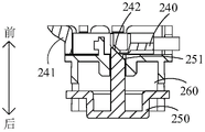
Fig. 13 is a schematic view of a locking structure of the battery pack and the vegetable cutter according to an embodiment of the present invention; FIG. 14 is a schematic view of the battery pack of FIG. 13 from another angle with respect to the locking structure of the shredder; fig. 15 is a cross-sectional view of a locking structure in the shredder of fig. 13.
Referring to fig. 13 to 15, in some embodiments, when the body is the vegetable cutter 200, the first clamping portion is a clamping block 241, and the battery pack 100 and the vegetable cutter 200 are assembled and disassembled by clamping the clamping block 241 with the first protrusion 125.
Referring to fig. 1, 13-15, in some embodiments, the vegetable cutter 200 includes a first locking member 240, a button 250 and a first elastic member, the button 250 is exposed through a bottom surface of the base 210, the button 250 includes a first inclined surface 251, and the first locking member 240 includes a second inclined surface 242. The first elastic member abuts against the first locking member 240, so that the second inclined surface 242 is attached to the first inclined surface 251, and the first elastic member is configured to push one of the two second clamping portions located at the rear end in the mounting direction to be relatively close to the first clamping portion through its own elastic force, specifically, push the clamping block 241 to be relatively close to the first protrusion 125. The button 250 can move towards the first locking member 240, so that the first inclined surface 251 pushes one of the two second clamping portions located at the rear end in the installation direction to be relatively far away from the first clamping portion by abutting against the second inclined surface 242, specifically, the clamping block 241 is pushed to be relatively far away from the first protrusion 125, wherein a direction in which the clamping block 241 is relatively far away from the first protrusion 125 is perpendicular to a moving direction of the button 250.
Specifically, in the perspective of fig. 13 and 15, the snap-in piece 241 is located at the left end of the first locking member 240, and the first protrusion 125 is located on the outer side wall of the battery can 210 located at the right side. The button 250 is exposed through the bottom surface of the base 210, and the second inclined surface 242 is matched with the first inclined surface 251 in shape and size so as to be attached to the same. One end of the first elastic member is connected to the first locking member 240, and the other end is directly or indirectly connected to the base 210. The position of the first elastic member is not limited as long as the first elastic member can support the first locking member 240 by its own elastic force, so that the first locking member has a movement tendency close to the battery pack 100, and meanwhile, it is also required that the first elastic member can support the first locking member 240 by its own elastic force, so that the second inclined surface 242 provided thereon has a tendency of moving toward the first inclined surface 251 to implement attachment. When the button 250 is pressed upward, the first inclined surface 251 will abut against the second inclined surface 242, so as to push the first locking member 240 to move in a direction away from the first protrusion 125 (i.e., to the right), thereby separating the latch 241 from the first protrusion 125 to achieve unlocking. When the button 250 is released, the first locking member 240 moves in a direction close to the first protrusion 125 (i.e., to the left) under the driving of the resilience force of the first elastic member, so that the clamping block 241 is clamped with the first protrusion 125 to achieve locking. Meanwhile, when the first locking member 240 moves to the left, the second inclined surface 242 resets by pushing the button 250 to move downward by abutting against the first inclined surface 251. In this embodiment, the movement of the button 250 in the vertical direction is converted into the horizontal movement of the catching block 241 by the inclined surface fit, so as to realize unlocking or locking. The structure enables the button 250 to be arranged on the base 210, and the button 250 is not exposed in the using process, so that the phenomenon that the battery pack 100 is disconnected and powered off due to mistaken touch of the button 250 in the working state can be avoided.
In some embodiments, the distance of the up and down movement of the button 250 is 2.5mm, the distance of the left and right movement of the first locking member 240 is 3mm, and the interference amount between the engaging block 241 and the first protrusion 125 in the moving direction of the first locking member 240 is 2mm.
With continued reference to fig. 13-15, in some embodiments, the vegetable cutter 200 includes a mounting bracket 260, the mounting bracket 260 is fixedly mounted on the base 210, the button 250 and the first locking member 240 are slidably connected to the mounting bracket 260, and the first elastic member is disposed between the first locking member 240 and the mounting bracket 260. Specifically, the mounting bracket 260 is provided with a first sliding slot 261 extending horizontally, and the first locking member 240 is installed in the first sliding slot 261. When the button 250 is pressed upward, the first locking member 240 slides rightward in the first sliding groove 261, and when the button 250 is released, the first locking member 240 slides leftward in the first sliding groove 261 under the driving of the resilient force of the first elastic member. The sliding of the first locking member 240 can be guided by the first sliding slot 261 to make the movement thereof more stable, and at the same time, the sliding of the first locking member 240 can be limited to make it have a proper sliding stroke. The mounting frame 260 is further provided with a second sliding slot 262 extending vertically, a main body part of the button 250 for being pressed is mounted in the inner cavity of the mounting frame 260, and an extension arm 252 connected to a side wall of the main body part of the button 250 extends into the second sliding slot 262. When the button 250 is pressed upwards, the extension arm 252 slides upwards in the second sliding groove 262, and when the button 250 is released, the button 250 moves downwards to be reset under the driving of the resilience force of the first elastic member, and the extension arm 252 slides downwards in the second sliding groove 262. The sliding of the button 250 can be guided by the second sliding groove 262 to make the movement thereof more stable. Meanwhile, the sliding of the button 250 can be limited, so that the button can slide upwards to reach an upper limit position when being blocked by the top wall of the second sliding groove 262.
Referring to fig. 16, in some embodiments, the battery pack 100 has a first depth extending into the first mounting cavity 211 through the first mounting opening and a second depth, the second depth being greater than the first depth. When the battery pack 100 extends into the first depth through the first mounting port, the battery pack 100 is in a mounting state; when the battery pack 100 moves from the first depth to the second depth, the battery pack 100 is switched to the detached state. Specifically, when the battery pack 100 is not installed, the battery pack 100 is pushed upward into the first installation cavity 211, and after the battery pack 100 is pushed to the first depth, the battery pack 100 will automatically realize locking and switch to the installation state. In the installation state, the battery pack 100 is continuously pushed upwards, and after the battery pack 100 is pushed to the second depth, the battery pack 100 is switched to the disassembly state, and can be withdrawn downwards from the first installation cavity 211.
Referring to fig. 16 and 17, in some embodiments, the vegetable cutter 200 includes a second locking member 270 and a limiting member 290, in a disassembled state, the battery pack 100 is configured to move toward the first installation cavity 211 and push the second locking member 270 to move synchronously until the battery pack 100 is clamped and fixed with the second locking member 270, and the second locking member 270 is limited by the limiting member 290 to maintain an installed state; in the mounted state, the battery pack 100 is configured to move continuously toward the first mounting cavity 211 and push the second locking member 270 to move synchronously, so that the second locking member 270 is separated from the position of the position-limiting member 290, and the battery pack 100 is separated from the second locking member 270. Specifically, when the battery pack 100 is not mounted, the battery pack 100 is pushed upward into the first mounting cavity 211, the second locking member 270 moves synchronously therewith, and after the battery pack 100 is pushed to a certain position, the second locking member 270 locks the position of the battery pack 100, and meanwhile, the second locking member 270 is limited at the current position by the limiting member 290 to maintain the locking of the battery pack 100. In the mounted state, the battery pack 100 is continuously pushed upward, the second locking member 270 moves synchronously therewith, after the battery pack 100 and the second locking member 270 move to a certain position, the second locking member 270 is separated from the limiting member 290, the battery pack 100 and the second locking member 270 can move in opposite directions, and when the battery pack 100 and the second locking member 270 move to a certain position, the battery pack 100 is separated from the second locking member 270, so that unlocking is realized.
Referring to fig. 16 to 19, in particular, in some embodiments, the vegetable cutter 200 includes a mounting sleeve 280, the limiting member 290 is connected to the mounting sleeve 280, a third sliding slot 281 is formed in the mounting sleeve 280, the second locking member 270 extends into the third sliding slot 281, a second elastic member 2100 is disposed between the second locking member 270 and the mounting sleeve 280, a limiting portion 276 is disposed on the second locking member 270, and the battery pack 100 includes a locking block 140. In a disassembled state, when the battery pack 100 is pressed, the second locking member 270 slides into the third sliding slot 281 along the installation direction under the support of the locking piece 140, and gradually folds under the limit of the third sliding slot 281, when the pressing of the battery pack 100 is stopped, the second locking member 270 slides out of the third sliding slot 281 along the reverse direction of the installation direction under the drive of the second elastic member 2100, and when the limiting member 290 locks the limiting portion 276, the second locking member 270 clasps the locking piece 140, and the installation of the battery pack 100 is completed. In the mounted state, when the battery pack 100 is pressed, the second locking member 270 slides into the third sliding slot 281 along the mounting direction under the support of the locking piece 140, so that the limiting member 290 is separated from the limiting portion 276, and when the pressing of the battery pack 100 is stopped, the second locking member 270 slides out of the third sliding slot 281 along the reverse direction of the mounting direction under the drive of the second elastic member 2100, and is gradually opened, so as not to clasp the locking piece 140, until the second locking member 270 is separated from the locking piece 140, that is, the dismounting of the battery pack 100 is completed.
Referring to fig. 17 to 23, in particular, the mounting sleeve 280 is fixedly mounted on the base 210 and extends into the first mounting cavity 211. The second locking member 270 includes a third clamping portion 271 and a fourth clamping portion 272, and a clamping groove 273 is defined between the third clamping portion 271 and the fourth clamping portion 272. The locking piece 140 is coupled to the top end of the battery pack 100. The third clamping portion 271 and the fourth clamping portion 272 are made of a material with certain elasticity, and when the third clamping portion 271 and the fourth clamping portion 272 are located outside the third sliding slot 281 of the mounting sleeve 280, the third clamping portion is in an open state, and the size of the formed clamping slot 273 is far larger than that of the locking block 140, so that the locking block 140 cannot be clamped. Pressing battery package 100 up, locking piece 140 will support in the cell wall of draw-in groove 273, makes second locking piece 270 slide in third spout 281 up, and third joint portion 271 and fourth joint portion 272 will draw in gradually under the limiting displacement of third spout 281, make draw-in groove 273 hug closely locking piece 140 gradually to with battery package 100 and second locking piece 270 fixed connection. When the second locking member 270 slides downwards, and slides to the time when the third clamping portion 271 and the fourth clamping portion 272 are separated from the third sliding slot 281, the third clamping portion 271 and the fourth clamping portion 272 are no longer limited by the third sliding slot 281, and will be opened and reset under the action of self resilience force, so as to release the locking of the battery pack 100. Preferably, along the installation direction, the width of third joint portion 271 and fourth joint portion 272 reduces gradually, so, can make the width of the junction of the main part of third joint portion 271 and fourth joint portion 272 and second locking piece 270 less, be favorable to third joint portion 271 and fourth joint portion 272 to open and draw in.
As described above, the third engaging portion 271 and the fourth engaging portion 272 are gradually drawn together under the limiting action of the third sliding slot 281, so that the engaging slot 273 gradually clasps the locking block 140, thereby fixedly connecting the battery pack 100 and the second locking member 270. In this process, in addition to the locking groove 273 tightly holding the locking piece 140, the second locking piece 270 needs to be limited to keep at the current position and not to exit the third sliding slot 281. As described above, the stopper portion 276 of the second locking member 270 is stopped by the stopper 290. Specifically, in some embodiments, the second locking member 270 is provided with a first limiting groove 274 and a second limiting groove 275 which are communicated with each other, the first limiting groove 274 and the second limiting groove 275 are disposed around the limiting portion 276, and the limiting member 290 moves in the first limiting groove 274 when the battery pack 100 is mounted; when the battery pack 100 is disassembled, the retaining member 290 moves in the second retaining groove 275. Specifically, an inlet of the first limiting groove 274 communicates with an outlet of the second limiting groove 275, and an outlet of the first limiting groove 274 communicates with an inlet of the second limiting groove 275. When the battery pack 100 is mounted, the limiting member 290 moves in the first limiting groove 274 until the limiting portion 276 is locked by the limiting member 290, and the second locking member 270 is fixed at the current position. When the battery pack 100 is disassembled, the limiting member 290 moves in the second limiting groove 275, the locking between the limiting portion 276 and the limiting member 290 is released, and the second locking member 270 exits the third sliding slot 281 under the driving of the second elastic member 2100. Thus, the movement paths of the limiting member 290 during installation and removal are different, so that the installation and removal can be performed independently and more stably.
Further, in some embodiments, the position-limiting portion 276 is in a "V" shape to form a locking groove 2762, the position-limiting portion 276 is provided with a first position-limiting surface 2761, and when the battery pack 100 is in an uninstalled state (the state shown in fig. 20), the position-limiting member 290 will engage with the first position-limiting surface 2761 and move relatively in the opposite direction of the installation direction until the position-limiting member exceeds the end of the first position-limiting surface 2761. When the pressing of the battery pack 100 is stopped, the second elastic element 2100 is driven, and the limiting element 290 will move relatively along the installation direction and be locked in the locking groove 2762 (the state shown in fig. 21), so as to limit the second locking element 270. Of course, the position-limiting portion 276 may also be "U" shaped, or other similar shapes. After the shape is set to be the same, the limiting member 290 is not easily separated from the locking groove 2762 after being clamped into the locking groove 2762, and the stability is better. The second limiting groove 275 further includes a second limiting surface 2751, and when the battery pack 100 is in the installation state (the state shown in fig. 22), the limiting member 290 will move relatively in the reverse direction of the installation direction when the battery pack 100 is pressed, and separate from the locking groove 2762, so as to release the limitation of the second locking member 270. Then, the limiting member 290 abuts against the second limiting surface 2751 and moves relative to the second limiting surface 2751 along the reverse direction of the installation direction. When the pressing of the battery pack 100 is stopped, the limiting member 290 will move relatively in the installation direction and reach the outlet of the second limiting groove 275 (the state shown in fig. 23) by the driving of the second elastic member 2100.
It should be noted that, in the foregoing process, the description is made in terms of the movement of the limiting member 290 relative to the second locking member 270. In practice, the component that moves absolutely is the second lock 270. However, the position-limiting member 290 needs to be able to swing to accommodate the path change in the width direction (horizontal direction in the view of fig. 19) of the first position-limiting groove 274 and the second position-limiting groove 275.
Referring to fig. 17 and 18, in particular, in some embodiments, the position-limiting member 290 is an elastic rod, which includes a body segment 291 and a free end 292, which are integrally connected. The main body segment 291 is fixedly connected to the groove wall of the mounting sleeve 280. The free end 292 is bent with respect to the main body section 291, and is caught by the free end 292 in the locking groove 2762, so as to limit the second locking element 270. The elastic rod itself has a certain elasticity, and in the moving process of fig. 20 to 21, when the free end 292 relatively moves along the first limiting surface 2761 in the reverse direction of the installation direction to the end beyond the first limiting surface 2761, the pressing of the battery pack 100 is stopped, and under the driving of the second elastic member 2100, the free end 292 will relatively move along the installation direction, and under the elastic force action of the elastic rod, the free end 292 will swing towards the right, and thus be clamped in the locking groove 2762. In the moving process of fig. 22 to 23, when the free end 292 abuts against the second limiting surface 2751 to move relatively, the pressing of the battery pack 100 is stopped, the free end 292 will move relatively along the installation direction under the driving of the second elastic member 2100, and under the elastic force of the elastic rod, the free end 292 will swing towards the left, thereby sliding along the second limiting groove 275 and reaching the outlet of the second limiting groove 275. Of course, besides using the elastic rod as the limiting member 290, other similar materials capable of swinging may be used, for example, a steel wire rope may also be used as the limiting member 290.
In the above process, the current position state of the free end 292 may be judged by the hand feeling when the battery pack 100 is pressed. For example, during the movement of fig. 20 to 21, when the free end 292 moves along the first limiting surface 2761 in the opposite direction of the installation direction, it will scrape against the first limiting surface 2761, and a certain resistance can be felt when pressing. When the free end 292 exceeds the end of the first limiting surface 2761, the first limiting surface 2761 is not scraped, the resistance is reduced or even disappears, and the battery pack 100 can be loosened. In the moving process of fig. 22 to 23, the free end 292 is separated from the locking groove 2762, and when the free end 292 abuts against the second limiting surface 2751 to move relatively, the free end and the second limiting surface 2751 may be scraped, and a certain resistance may be felt when pressing, so that the battery pack 100 may be released.
Referring to FIG. 22, in some embodiments, when the free end 292 of the elastic rod is engaged with the locking groove 2762, the start end of the second limiting surface 2751 is located at a side of the limiting member 290 close to the first limiting groove 274. That is, in the view of fig. 22, the beginning of the second limiting surface 2751 is located at the left side of the free end 292, and the distance between the two is a. Thus, when the battery pack 100 is in the mounted state (the state shown in fig. 22), when the battery pack 100 is pressed, the free end 292 can be smoothly abutted against the second limiting surface 2751 and relatively move in the second limiting groove 275 when moving relatively in the reverse direction of the mounting direction, so that the battery pack 100 can be smoothly disassembled. If the free end 292 is cylindrical with a radius b, preferably, a > 1.5b, to prevent the free end 292 from returning to the first restraint slot 274 and re-engaging the locking slot 2762.
Referring to fig. 18, in some embodiments, the elastic rod has two free ends 292, and the front and back surfaces of the second locking element 270 are respectively provided with a set of the aforementioned limiting portion 276, the first limiting groove 274 and the second limiting groove 275, and each set is matched with one free end 292 for limiting. Thus, the second locking member 270 can be more stably limited.
Referring to fig. 17, in some embodiments, the second locking element 270 is provided with a receiving groove 277, the second elastic element 2100 is disposed in the receiving groove 277, one end of the second elastic element 2100 is fixedly connected to a groove wall of the receiving groove 277, and the other end of the second elastic element is abutted against a fixed connection of the third sliding groove 281. When the second locking member 270 is outwardly ejected by the resilient force of the second elastic member 2100, the second elastic member 2100 is prevented from completely falling out of the third sliding groove 281 because the second elastic member 2100 is fixedly connected to the groove wall of the receiving groove 277. A guide post may be disposed in the receiving groove 277, and the second elastic member 2100 may be sleeved on the guide post to guide the second elastic member 2100.
Referring to fig. 1 and 8, in some embodiments, the outer contours of the base 210, the motor 230, and the battery pack 100 projected along the installation direction are all circular or quasi-circular, and the motor 230 is located in the center of the working cavity along the radial direction of the base 210; the radius of the base 210 is R, the diameter of the battery pack 100 is d, the radius of the motor 230 is R, R = K (d + R), wherein K is greater than or equal to 1 and less than or equal to 1.2. Specifically, the quasi-circular shape may be an approximately circular shape, such as a polygon or an ellipse. The projection of the motor 230 is located at the center of the projection of the base 210 in a plane perpendicular to the mounting direction. The motor 230 and the battery pack 100 are arranged in a staggered manner on the axis of the output shaft of the motor 230, that is, the battery pack 100 is located outside the motor 230 in the radial direction of the base 210. When K =1 is satisfied, that is, R = d + R, the radial dimension of the base 210 can be minimized, which is beneficial to the miniaturization design of the kitchen appliance, so that the requirement of the corresponding placement space of the kitchen appliance is low.
Fig. 9 is a position distribution diagram (top view) of the motor and the battery pack in the kitchen appliance of fig. 1.
Referring to fig. 1 and 9, in some embodiments, in the installed state, in a plane perpendicular to the installation direction, a projection of the center of the battery pack 100 is a first position a, a projection of the center of the motor 230 is a second position B, a projection of the center of gravity of the kitchen appliance is a third position C, and the third position C passes through a connection line between the first position a and the second position B. When the projection of the installation positions of the battery pack 100 and the motor 230 meets the above conditions, the weight of the battery pack 100 and the weight of the motor 230 can be well balanced, so that the whole kitchen appliance is better in stability after installation and is not prone to shaking or toppling.
With continued reference to FIGS. 1 and 9, preferably, in some embodiments, the distance between the second position B and the third position C is s, the weight of the battery pack 100 is m, and 0.024 ≦ s/m ≦ 0.032. When the above range is satisfied, the weight of the battery pack 100 and the weight of the motor 230 can be further well balanced, and the whole kitchen appliance has better stability after being installed and is not easy to shake or topple. Specifically, in some embodiments, the weight m of the battery pack 100 is 100g, and the weight of the kitchen appliance before the battery pack 100 is installed ranges from 1100g to 1500g. The spacing s between the second position B and the third position C is in the range of 4.89mm to 6.39mm. Preferably, the first position A is spaced from the second position B by a distance in the range of 40mm to 45mm.
Referring to fig. 2, in some embodiments, the body is a mixer 300, the mixer 300 includes a second body 310, a handle 320, and a mixing head 330 capable of mixing by being driven by a motor, one side of the second body 310 is connected to the handle 320, the other side is connected to the mixing head 330, the extending direction of the handle 320 is substantially parallel to the extending direction of the second body 310, and the extending direction of the mixing head 330 is substantially perpendicular to the extending direction of the second body 310; the second mounting opening is located on a side wall of the handle 320 facing away from the stirring head 330, and the second mounting cavity 340 extends from the inside of the handle 320 to the inside of the second body 310. Specifically, substantially perpendicular refers to an included angle in the range of 80 degrees to 90 degrees, and substantially parallel refers to an included angle of no more than 10 degrees. The handle 320, the second body 310 and the mixing head 330 are arranged along the installation direction, the handle 320 is connected to the rear side of the second body 310, and the mixing head 330 is connected to the front side of the second body 310. The second mounting opening is located in the rear sidewall of the handle 320. The second mounting cavity 340 extends from the inside of the handle 320 to the inside of the second body 310 along the mounting direction, and after the battery pack 100 is mounted in place, part of the second mounting cavity is located in the handle 320 and part of the second mounting cavity is located in the second body 310.
Referring to fig. 2 and 4, further, in some embodiments, two second locking portions are disposed at intervals on the side wall of the battery pack 100 along the installation direction, and one of the two second locking portions, which is located at the front end in the installation direction, is adapted to the first locking portion in the mixer 300. Specifically, the first protrusion 125 and the second protrusion 126 are disposed at an interval along the mounting direction on the sidewall of the battery pack 100, wherein the second protrusion 126 is adapted to the first engaging portion of the mixer 300. Of course, in other embodiments, the position of the first clamping portion in the stirrer 300 can be adjusted at the design time, so that the first bump 125 is used for adapting the first clamping portion in the stirrer 300.
With continued reference to fig. 2 and 4, in some embodiments, the handle 320 is connected to the second body 310 through a connecting portion 350, an extending direction of the connecting portion 350 is substantially perpendicular to an extending direction of the second body 310, and the second installation cavities 340 are distributed at least on the handle 320 and the connecting portion 350. The ratio of the radial dimension of the battery pack 100 to the dimension of the connecting part 350 along the radial direction of the battery pack 100 ranges from 0.63 to 0.96, and the ratio of the axial dimension of the battery pack 100 to the sum of the dimensions of the handle 320, the connecting part 350 and the second body 310 along the axial direction of the battery pack 100 ranges from 0.5 to 0.7. Specifically, the handle 320, the connection part 350, the second body 310 and the mixing head 330 are arranged along the installation direction, and the handle 320 is connected to the rear side of the second body 310 through the connection part 350. The second mounting cavity 340 extends forward from the rear sidewall of the handle 320 to the inside of the second body 310 through the connecting portion 350, that is, in the mounting direction, the second mounting cavity 340 is partially located in the handle 320, partially located in the connecting portion 350, and partially located in the second body 310. The axial direction of the battery pack 100 is parallel to the mounting direction, and the radial dimension of the battery pack 100 refers to a dimension perpendicular to the mounting direction thereof. When the second mounting cavity 340 is provided as described in the previous embodiment, the size of the connection part 350 in the radial direction of the battery pack 100 may be minimized, and the structure may be more compact. Meanwhile, the inner space of the handle 320, the connecting part 350 and the second body 310 along the axial direction of the battery pack 100 can be better utilized, and the structure can be more compact.
Referring to fig. 3, in some embodiments, the housing is a handheld food processor 400, and the handheld food processor 400 includes a third housing 410 and a grinding head 420 capable of being driven by a motor to grind and crush; the third mounting chamber 411 is located inside the third body 410, one end of the third body 410 in the extending direction thereof is connected to the polishing head 420, and the other end thereof is provided with a third mounting opening. Specifically, the handheld food processor 400 is cylindrical or quasi-cylindrical as a whole. The third body 410 and the polishing head 420 are arranged along the mounting direction, and the polishing head 420 is connected to the front end of the third body 410. A third mounting hole is formed in a rear end wall of the third body 410, and a third mounting cavity 411 extends forward from the rear end wall of the third body 410.
Referring to fig. 3 and 4, further, in some embodiments, two second clamping portions are disposed at intervals on the side wall of the battery pack 100 along the installation direction, and one of the two second clamping portions, which is located at the front end in the installation direction, is adapted to the first clamping portion in the handheld food processor 400. Specifically, the first protrusion 125 and the second protrusion 126 are disposed at an interval on the sidewall of the battery pack 100 along the installation direction, wherein the second protrusion 126 is adapted to the first clamping portion of the handheld food processor 400.
Referring to fig. 3 and 4, in some embodiments, the ratio of the radial dimension of the battery pack 100 to the dimension of the third body 410 along the radial direction of the battery pack 100 ranges from 0.62 to 0.95, and the ratio of the axial dimension of the battery pack 100 to the dimension of the third body 410 along the axial direction of the battery pack 100 ranges from 0.1 to 0.3. Specifically, the axial direction of the battery pack 100 is parallel to the mounting direction and the axial direction of the third body 410, the radial direction of the battery pack 100 refers to a direction perpendicular to the mounting direction thereof, and the radial direction of the third body 410 refers to a direction perpendicular to the axial direction thereof. Compared with the installation mode that the installation direction is perpendicular to the axial direction of the third machine body 410, when the third installation cavity 411 is arranged and the battery pack 100 is installed according to the mode shown in fig. 3, the size of the third machine body 410 in the axial direction of the third machine body is large, so that the internal space of the third machine body 410 can be fully utilized when the battery pack 100 is installed in the direction, the radial size of the third machine body 410 is reduced as much as possible, the miniaturization of the device is facilitated, and the holding by a user is facilitated.
Fig. 5 is a schematic view of the battery pack of fig. 4 from another angle.
Referring to fig. 4 and 5, in some embodiments, the battery pack 100 includes a display screen for displaying the remaining power, and the display screen is located at the rear end of the battery pack 100 along the installation direction, where the installation direction is the direction in which the battery pack 100 moves into the installation cavity through the installation opening. After the battery pack 100 is installed on the machine body, the rear end of the battery pack 100 is exposed through the installation opening, so that the display screen arranged at the rear end of the battery pack 100 can be directly exposed through the installation opening, and a user can directly observe the electric quantity of the battery pack 100 without detaching the battery pack 100. Meanwhile, because the display screen 150 is exposed through the mounting opening, the user can timely know the current electric quantity of the battery pack 100, so that the battery pack 100 which is fully charged can be replaced after the battery pack 100 which is not sufficiently charged is timely detached, and the situation that the electric quantity is insufficient when the kitchen appliance is carried out for use is not easy to occur. In addition, because the user can in time learn the current electric quantity of battery package 100, can in time change full-power battery package 100 after dismantling the battery package 100 that the electric quantity is not enough for the battery package 100 of kitchen electrical apparatus is in the state that the electric quantity is comparatively sufficient always, when needing to carry the kitchen electrical apparatus out, can take along with walking, when the time is comparatively urgent, need not to delay time and check whether the electric quantity is sufficient and know to change battery package 100 after the electric quantity is not enough in the inspection. Of course, in other embodiments, the display screen may protrude outward from the sidewall of the battery pack 100 in the radial direction of the battery pack 100. The projection profile of the battery pack 100 along the mounting direction is circular or quasi-circular, and the radial direction thereof is a direction perpendicular to the mounting direction.
Referring to fig. 4 and 5, in some embodiments, the direction in which the battery pack 100 moves into the mounting cavity through the mounting opening is taken as a mounting direction, and a rear end of the battery pack 100 along the mounting direction protrudes from a surface of the machine body or is flush with the surface of the machine body. Specifically, in the embodiment shown in fig. 2, the rear end of the battery pack 100 in the mounting direction protrudes from the rear sidewall of the handle 320 in the blender 300, so that the user can observe the amount of electricity. Similarly, in the embodiment shown in fig. 3, the rear end of the battery pack 100 in the mounting direction protrudes from the rear end wall of the third body 410 of the handheld food processor 400. However, in the embodiment shown in fig. 1, the rear end of the battery pack 100 along the installation direction cannot exceed the bottom surface of the base 210 of the vegetable cutter 200, so as to prevent the vegetable cutter 200 from being placed on the carrying surface. Preferably, the rear end of the battery pack 100 in the mounting direction may be flush with the bottom surface of the base 210 in the vegetable cutter 200. So that the battery pack 100 is also supported by the supporting surface to lift the battery pack 100. If the first clamping portion of the vegetable cutter 200 fails, the battery pack 100 is still located in the first mounting cavity 211 and cannot be pulled out because the battery pack 100 is supported by the bearing surface.
In the above embodiments, the display screen is located at the rear end of the battery pack 100 along the installation direction, and in other embodiments, the display screen may also be disposed on the machine body. Specifically, the display screen is mounted on the body, and the screen is exposed on the surface of the body. After the battery pack 100 is mounted on the body and electrically connected, the display screen may display the remaining power of the battery pack 100. When the battery pack 100 is detached from the body, the display screen displays that the battery pack 100 is in an uninstalled state.
Referring to fig. 1 to 4, in some embodiments, a direction in which the battery pack 100 moves into the mounting cavity through the mounting opening is taken as a mounting direction, and a projected outline of the mounting cavity along the mounting direction coincides with a projected outline of the battery pack 100 along the mounting direction. Specifically, the maximum dimension of the mounting cavity in the radial direction of the battery pack 100 is equal to the maximum dimension of the battery pack 100 in the radial direction. So, after battery package 100 packs into the installation cavity, at least part region can laminate with the chamber wall of installation cavity on the lateral wall of battery package 100, and dust and liquid are difficult for getting into the installation cavity between the chamber wall of battery package 100 and installation cavity to can strengthen waterproof dirt resistance.
Fig. 10 is an exploded view of the battery pack of fig. 4.
Referring to fig. 4, 5 and 10, further, in some embodiments, the battery pack 100 includes an attaching portion, the attaching portion is located on at least a partial region of a side wall of the battery pack 100 along the installation direction, and in the installation state, the attaching portion is attached to a wall of the installation cavity. Specifically, a partial region on the outer side wall of the battery pack 100 protrudes outward in the radial direction of the battery pack 100, thereby forming a fitting portion. The size of the fitting portion is substantially equal to the size of the mounting cavity in the radial direction of the battery pack 100. Further, a region on the outer side wall of the battery pack 100 near the rear end protrudes outward in the radial direction of the battery pack 100, thereby forming the fitting portion. So, can be close to installation department with the installation cavity shutoff, make dust and liquid basically can't get into the installation intracavity completely, waterproof dirt resistance is better.
FIG. 6 is a front view of the battery pack of FIG. 4 in an embodiment of the present application; fig. 7 is a top view of the battery pack of fig. 4 in an embodiment of the present application.
Referring to fig. 4, 5 and 10, in some embodiments, the battery pack 100 includes a housing and three battery cells 130 disposed in the housing, and a direction in which the battery pack 100 moves into the mounting cavity through the mounting opening is taken as a mounting direction, and a central connection line of projections of the three battery cells 130 along the mounting direction forms a triangle. The three battery cells 130 are distributed in a triangular shape, so that the radial distribution of the battery pack 100 is more compact, and the radial size of the battery pack 100 is smaller, so that the radial size of the base 210 in the vegetable cutter 200 shown in fig. 1 is smaller, and the radial size of the third body 410 of the handheld food processor 400 shown in fig. 3 is smaller. Referring to fig. 5 to 7, the battery pack 100 has a cylindrical shape or a cylinder-like shape, and a radial direction thereof is a direction perpendicular to the mounting direction. When the central lines of the projections of the three battery cells 130 in the mounting direction form a triangle, the radial size of the battery pack 100 ranges from 38mm to 55mm. Preferably, the length L4 of the entire battery pack 100 is 47mm, the width L3 is 42mm, the sum of the heights L1+ L2 is 96mm, and the case wall thickness is 1.5mm.
It can be understood that, in some embodiments, the central connecting lines of the projections of the three battery cells 130 along the installation direction form a regular triangle, and at this time, the three battery cells 130 are distributed more compactly in the radial direction of the battery pack 100, and the radial dimension of the battery pack 100 is smaller.
Fig. 11 is a structural schematic diagram of a second shell portion of the battery pack in fig. 4.
Referring to fig. 4, 10 and 11, in some embodiments, the case includes a first case portion 110 and a second case portion 120 sequentially arranged along an installation direction, a circuit board is installed in the first case portion 110, and a battery cell 130 is installed in the second case portion 120. Referring to FIG. 6, a dimension of the first case portion 110 in the mounting direction is L1, a dimension of the second case portion 120 in the mounting direction is L2, and L1/L2 is 0.2 ≦ L1 ≦ 0.4. When the ratio of the sizes of the first and second case parts 110 and 120 in the mounting direction satisfies the above-described condition, the size of the entire battery pack 100 in the mounting direction can be made smaller on the premise of having sufficient space to mount the battery cells 130 and the circuit boards.
Specifically, the first case part 110 is detachably coupled with the second case part 120. An area of an exterior side wall of the second shell portion 120 adjacent to the first shell portion 110 protrudes outward to form a convex ring 124, and a radial dimension of an exterior side wall of the convex ring 124 is equal to a radial dimension of an exterior side wall of the first shell portion 110. The outer side wall of the convex ring 124 and the outer side wall of the first shell portion 110 together form the aforementioned fitting portion.
Referring to fig. 4, 10 and 11, in some embodiments, the first shell portion 110 is connected with the second shell portion 120 by a threaded fastener; and/or the first shell part 110 is clamped with the second shell part 120. Specifically, the first shell portion 110 and the second shell portion 120 may be connected by a threaded fastener such as a screw. Or, the first housing part 110 and the second housing part 120 are fixedly installed by clamping. Alternatively, the first and second case parts 110 and 120 are fixedly mounted in both of the above-described manners.
Referring to fig. 4, 10 and 11, specifically, in some embodiments, the first shell portion 110 is provided with a plurality of hooks 111 arranged at intervals along the circumferential direction of the battery pack 100, the second shell portion 120 is provided with a plurality of clamping blocks 121 arranged at intervals along the circumferential direction of the battery pack 100, and the plurality of clamping blocks 121 are clamped into the plurality of hooks 111 in a one-to-one correspondence manner; and, a plurality of connection posts 112 are arranged on the first case portion 110 at intervals along the circumferential direction of the battery pack 100, and the connection posts 112 extend into the second case portion 120 and are connected with the second case portion 120 through threaded fasteners.
Specifically, the first shell portion 110 is provided with three hooks 111 arranged at intervals along the circumferential direction of the battery pack 100, correspondingly, the second shell portion 120 is provided with three blocks 121 arranged at intervals along the circumferential direction of the battery pack 100, and each block 121 is correspondingly clamped into one hook 111. Meanwhile, the first shell portion 110 is provided with two connecting posts 112 arranged at intervals along the circumferential direction of the battery pack 100, correspondingly, the second shell portion 120 is provided with two connecting sleeves 122 arranged at intervals along the circumferential direction of the battery pack 100, and each connecting post 112 correspondingly extends into one connecting sleeve 122 and is connected through a screw. In this embodiment, the first housing portion 110 and the second housing portion 120 are fixedly mounted by clamping and fastening with a screw fastener, so that the fixing strength of the two housings can be improved.
Referring to fig. 4, 10 and 11, in some embodiments, a female terminal is disposed at a front end of the second housing part 120 along the mounting direction, a male terminal is disposed on the machine body, and the female terminal and the male terminal are plugged to electrically connect the battery pack 100 and the machine body. Specifically, the female terminal is a slot 131, and the slot 131 is electrically connected to the battery cell 130. A through groove 123 is formed at a front end surface of the second case portion 120, and the insertion groove 131 is exposed through the through groove 123. The male terminal is a pin disposed on the body, and the pin is inserted into the slot 131 to electrically connect the two, so that the battery pack 100 is electrically connected to the body. In other embodiments, the positions of the socket and the pin may be interchanged.
Fig. 12 is a schematic structural diagram of a charging stand in an embodiment of the present application.
Referring to fig. 12, in some embodiments, the kitchen appliance includes a charging base 500, the battery pack 100 is detachably connected to the charging base 500, and the battery pack 100 separated from the body can be connected to the charging base 500 for charging. Specifically, the charging socket 510 is disposed on the charging socket 500, and after the battery pack 100 is detached from the body, the battery pack can be electrically connected to the charging socket 500 by being plugged into the charging socket 510, so as to achieve charging. The battery pack 100 can be alternately used and charged to improve the cruising ability of various organisms.
The technical features of the embodiments described above may be arbitrarily combined, and for the sake of brevity, all possible combinations of the technical features in the embodiments described above are not described, but should be considered as being within the scope of the present specification as long as there is no contradiction between the combinations of the technical features.
The above-mentioned embodiments only express several implementation modes of the present application, and the description thereof is specific and detailed, but not to be construed as limiting the scope of the present application. It should be noted that, for a person skilled in the art, several variations and modifications can be made without departing from the concept of the present application, which falls within the scope of protection of the present application. Therefore, the protection scope of the present application shall be subject to the appended claims.
Claims (35)
1. Kitchen appliance, characterized in that includes:
the device comprises a machine body, a first fixing device and a second fixing device, wherein a mounting cavity is formed in the machine body and provided with a mounting opening positioned on the surface of the machine body; and
a battery pack (100) detachably connected to the body;
the battery pack (100) is provided with an installation state and a disassembly state, in the disassembly state, the battery pack (100) can move into or out of the installation cavity through the installation opening, and after the battery pack (100) is separated from the machine body, the installation cavity is exposed out of the surface of the machine body; in the installation state, the battery pack (100) is installed in the installation cavity, and one end of the battery pack (100) is exposed through the installation opening.
2. Kitchen appliance according to claim 1, characterized in that the body comprises a first snap-in portion and the battery pack (100) comprises a second snap-in portion;
in the installation state, the first clamping portion is clamped in the second clamping portion.
3. The kitchen appliance according to claim 2, wherein the battery pack (100) comprises a plurality of said second snap portions for adapting to said first snap portions in different types of said bodies, respectively.
4. The kitchen appliance according to claim 3, wherein the direction in which the battery pack (100) is moved into the mounting cavity through the mounting opening is taken as a mounting direction, and the plurality of second clamping portions are arranged on the side wall of the battery pack (100) at intervals along the mounting direction.
5. The kitchen appliance according to claim 4, wherein the machine body is a vegetable cutter (200), a juice extractor or a meat grinder, the machine body comprises a base (210) and a first machine body (220), the first machine body (220) is detachably connected to the base (210), a motor (230) is installed in the base (210), the first machine body (220) comprises a working cavity, a cutting piece is installed in the working cavity, and the cutting piece is driven by the motor (230) to rotate so as to cut;
the installation cavity is located in the base (210), and the installation opening is located the bottom surface of base (210).
6. The kitchen appliance according to claim 5, wherein two of the second clamping portions are disposed at an interval on a side wall of the battery pack (100) along the mounting direction, and one of the two second clamping portions located at a rear end in the mounting direction is used for adapting to the first clamping portion in the vegetable cutter (200), the juice extractor or the meat grinder.
7. The kitchen appliance of claim 6, wherein the vegetable cutter (200) includes a first locking member (240), a button (250), and a first resilient member, wherein the button (250) is exposed through a bottom surface of the base (210), wherein the button (250) includes a first sloped surface (251), and wherein the first locking member (240) includes a second sloped surface (242);
the first elastic piece abuts against the first locking piece (240) so that the second inclined surface (242) is attached to the first inclined surface (251), and the first elastic piece is configured to push the first clamping portion to be relatively close to the second clamping portion through the elastic force of the first elastic piece;
the button (250) can move towards the first locking part (240) so that the first inclined surface (251) pushes the first clamping portion and the second clamping portion to be relatively far away by abutting against the second inclined surface (242), wherein the direction of the first clamping portion and the second clamping portion which are relatively far away is perpendicular to the moving direction of the button (250).
8. The kitchen appliance according to claim 7, wherein the vegetable cutter (200) comprises a mounting bracket (260), the mounting bracket (260) is fixedly mounted on the base (210), the button (250) and the first locking member (240) are both slidably connected to the mounting bracket (260), and the first elastic member is disposed between the first locking member (240) and the mounting bracket (260).
9. The kitchen appliance according to claim 6, wherein the battery pack (100) has a first depth extending into the mounting cavity through the mounting opening and a second depth, the second depth being greater than the first depth;
when the battery pack (100) extends into the first depth through the mounting opening, the battery pack (100) is in the mounting state; when the battery pack (100) moves from the first depth to the second depth, the battery pack (100) is switched to the detached state.
10. The kitchen appliance according to claim 9, wherein the vegetable cutter (200) comprises a second locking member (270) and a retaining member (290), and in the disassembled state, the battery pack (100) is configured to move towards the installation cavity and push the second locking member (270) to move synchronously until the battery pack (100) is clamped and fixed with the second locking member (270), and the second locking member (270) is retained by the retaining member (290) to maintain the assembled state; in the mounting state, the battery pack (100) is configured to continue to move towards the mounting cavity and push the second locking piece (270) to move synchronously, so that the second locking piece (270) is separated from the limiting piece (290), and the battery pack (100) is separated from the second locking piece (270).
11. The kitchen appliance according to claim 10, wherein the vegetable cutter (200) comprises a mounting sleeve (280), the limiting member (290) is connected to the mounting sleeve (280), a third sliding slot (281) is formed in the mounting sleeve (280), the second locking member (270) extends into the third sliding slot (281), a second elastic member (2100) is arranged between the second locking member (270) and the mounting sleeve (280), a limiting portion (276) is formed on the second locking member (270), and the battery pack (100) comprises a locking block (140);
in the disassembled state, when the battery pack (100) is pressed, the second locking piece (270) slides into the third sliding groove (281) along the installation direction under the support of the locking piece (140) and gradually folds under the limit of the third sliding groove (281), when the battery pack (100) is stopped to be pressed, the second locking piece (270) slides out of the third sliding groove (281) along the reverse direction of the installation direction under the drive of the second elastic piece (2100), and until the limiting piece (290) locks the limiting part (276), the second locking piece (270) clasps the locking piece (140);
in the installation state, when the battery pack (100) is pressed, the second locking piece (270) slides into the third sliding groove (281) along the installation direction under the support of the locking block (140) so as to separate the limiting piece (290) from the limiting part (276), and when the battery pack (100) is stopped to be pressed, the second locking piece (270) slides out of the third sliding groove (281) along the reverse direction of the installation direction under the drive of the second elastic piece (2100) and is gradually opened until the second locking piece (270) is separated from the locking block (140).
12. The kitchen appliance according to claim 11, wherein the second locking member (270) is provided with a first limiting groove (274) and a second limiting groove (275) which are communicated with each other, the first limiting groove (274) and the second limiting groove (275) are arranged around the limiting portion (276), and the limiting member (290) moves in the first limiting groove (274) when the battery pack (100) is mounted; when the battery pack (100) is disassembled, the limiting piece (290) moves in the second limiting groove (275).
13. The kitchen appliance according to claim 12, wherein the limiting portion (276) is V-shaped to form a locking groove (2762), a first limiting surface (2761) is provided on the limiting portion (276), and the second limiting groove (275) comprises a second limiting surface (2751);
in the disassembled state, when the battery pack (100) is pressed, the limiting piece (290) is attached to the first limiting surface (2761) to move relatively in the reverse direction of the installation direction, and when the battery pack (100) is stopped being pressed, the limiting piece (290) moves relatively in the installation direction and is clamped in the locking groove (2762);
in the mounting state, when the battery pack (100) is pressed, the limiting piece (290) is separated from the locking groove (2762) and is attached to the second limiting surface (2751) in the reverse direction of the mounting direction to move relatively, and when the battery pack (100) is stopped being pressed, the limiting piece (290) moves relatively in the mounting direction and reaches the outlet of the second limiting groove (275).
14. Kitchen appliance according to claim 13, characterized in that the stop (290) is a resilient rod, which is fixedly connected with the mounting sleeve (280), and that a free end (292) of the resilient rod is bent with respect to a main body section (291) of the resilient rod, which free end (292) can be snapped into the locking groove (2762).
15. The kitchen appliance according to claim 5, wherein the base (210), the motor (230) and the battery pack (100) have a circular or quasi-circular outer contour in the projection along the mounting direction, and the motor (230) is located in the working cavity at a central position along the radial direction of the base (210);
the radius of the base (210) is R, the diameter of the battery pack (100) is d, the radius of the motor (230) is R, R = K (d + R), and K is more than or equal to 1 and less than or equal to 1.2.
16. Kitchen appliance according to claim 5, characterized in that in the mounted state, in a plane perpendicular to the mounting direction, the projection of the center of the battery pack (100) is a first position, the projection of the center of the motor (230) is a second position, and the projection of the center of gravity of the kitchen appliance is a third position, which third position passes through a line connecting the first position and the second position.
17. The kitchen appliance according to claim 16, wherein the second position is spaced from the third position by s, the weight of the battery pack (100) is m,0.024 ≦ s/m ≦ 0.032.
18. The kitchen appliance according to claim 4, wherein the body is a stirrer (300), the stirrer (300) comprises a second body (310), a handle (320), and a stirring head (330) capable of stirring by being driven by a motor, one side of the second body (310) is connected to the handle (320), the other side of the second body is connected to the stirring head (330), the handle (320) extends in a direction substantially parallel to the second body (310), and the stirring head (330) extends in a direction substantially perpendicular to the second body (310);
the mounting opening is located the lateral wall that deviates from stirring head (330) on handle (320), the installation cavity extends to inside the second fuselage (310) from inside handle (320).
19. The kitchen appliance according to claim 18, wherein two of the second snap-in portions are provided at intervals along the mounting direction on a side wall of the battery pack (100), and one of the two second snap-in portions, which is located at a front end in the mounting direction, is adapted to the first snap-in portion in the mixer (300).
20. The kitchen appliance according to claim 18, wherein the handle (320) is connected to the second body (310) by a connecting portion (350), the connecting portion (350) extends in a direction substantially perpendicular to the second body (310), and the installation cavities are distributed at least in the handle (320) and the connecting portion (350);
the ratio range of the radial dimension of the battery pack (100) to the radial dimension of the connecting part (350) along the battery pack (100) is 0.63-0.96, and the ratio range of the axial dimension of the battery pack (100) to the sum of the axial dimensions of the handle (320), the connecting part (350) and the second machine body (310) along the battery pack (100) is 0.5-0.7.
21. The kitchen appliance according to claim 4, wherein the body is a hand-held food processor (400), the hand-held food processor (400) comprising a third body (410), and a grinding head (420) capable of being driven by a motor for grinding and crushing;
the mounting cavity is located inside the third machine body (410), one end of the third machine body (410) in the extending direction of the third machine body is connected to the grinding head (420), and the other end of the third machine body is provided with the mounting opening.
22. The kitchen appliance according to claim 21, wherein two of the second engaging portions are disposed on the sidewall of the battery pack (100) at intervals along the mounting direction, and one of the two second engaging portions located at the front end in the mounting direction is adapted to the first engaging portion in the handheld food processor (400).
23. Kitchen appliance according to claim 21, characterized in that the ratio of the radial dimension of the battery pack (100) to the dimension of the third body (410) in the radial direction of the battery pack (100) is in the range 0.62-0.95 and the ratio of the axial dimension of the battery pack (100) to the dimension of the third body (410) in the axial direction of the battery pack (100) is in the range 0.1-0.3.
24. The kitchen appliance according to any of claims 1 to 23, wherein the kitchen appliance comprises a display screen for displaying the remaining power of the battery pack (100), the display screen being provided to the body.
25. The kitchen appliance according to any of the claims 1 to 23, wherein the battery pack (100) comprises a display screen for displaying a remaining power, the display screen being located at a rear end of the battery pack (100) in the mounting direction, with a direction in which the battery pack (100) is moved into the mounting cavity through the mounting opening being the mounting direction.
26. The kitchen appliance according to claim 25, wherein a direction in which the battery pack (100) is moved into the mounting cavity through the mounting opening is taken as a mounting direction, and a rear end of the battery pack (100) along the mounting direction is protruded from a surface of the machine body or is flush with the surface of the machine body.
27. The kitchen appliance according to any of claims 1 to 23, characterized in that a direction in which the battery pack (100) is moved into the mounting cavity through the mounting opening is a mounting direction, a projected contour of the mounting cavity in the mounting direction coinciding with a projected outer contour of the battery pack (100) in the mounting direction.
28. The kitchen appliance according to claim 27, wherein the battery pack (100) comprises an abutment portion at least in a partial region of a side wall of the battery pack (100) in the mounting direction, the abutment portion abutting a wall of the mounting cavity in the mounted state.
29. The kitchen appliance according to any of the claims 1 to 23, wherein the battery pack (100) comprises a housing and three battery cells (130) arranged in the housing, and a central connecting line of projections of the three battery cells (130) along the mounting direction forms a triangle with a direction in which the battery pack (100) moves into the mounting cavity through the mounting opening as the mounting direction.
30. The kitchen appliance according to claim 29, wherein the center connecting lines of the projections of the three battery cells (130) in the mounting direction form a regular triangle.
31. The kitchen appliance according to claim 29, wherein the housing comprises a first housing part (110) and a second housing part (120) arranged in sequence along the installation direction, a circuit board is installed in the first housing part (110), and the battery cell (130) is installed in the second housing part (120);
the size of the first shell part (110) along the installation direction is L1, the size of the second shell part (120) along the installation direction is L2, and L1/L2 is more than or equal to 0.2 and less than or equal to 0.4.
32. The kitchen appliance according to claim 31, wherein the first shell portion (110) and the second shell portion (120) are connected by a threaded fastener; and/or the first shell part (110) is clamped with the second shell part (120).
33. The kitchen appliance according to claim 32, wherein the first housing portion (110) is provided with a plurality of hooks (111) arranged at intervals along the circumferential direction of the battery pack (100), the second housing portion (120) is provided with a plurality of clamping blocks (121) arranged at intervals along the circumferential direction of the battery pack (100), and the plurality of clamping blocks (121) are clamped into the plurality of hooks (111) in a one-to-one correspondence manner; and the number of the first and second groups,
the battery pack is characterized in that a plurality of connecting columns (112) are arranged on the first shell portion (110) at intervals along the circumferential direction of the battery pack (100), and the connecting columns (112) extend into the second shell portion (120) and are connected with the second shell portion (120) through threaded fasteners.
34. The kitchen appliance according to claim 31, wherein the second housing part (120) is provided with a female terminal at a front end along the mounting direction, and a male terminal is provided on the machine body, and the female terminal is plugged with the male terminal to electrically connect the battery pack (100) with the machine body.
35. A kitchen appliance as claimed in claim 1, characterized in that the kitchen appliance comprises a charging stand (500), the battery pack (100) being detachably connected to the charging stand (500), the battery pack (100) being separable from the body being connectable to the charging stand (500) for charging.
Priority Applications (3)
| Application Number | Priority Date | Filing Date | Title |
|---|---|---|---|
| CN202221198596.7U CN217852603U (en) | 2022-05-18 | 2022-05-18 | Kitchen appliance |
| PCT/CN2022/136549 WO2023221459A1 (en) | 2022-05-18 | 2022-12-05 | Kitchen appliance |
| KR1020247001852A KR20240025607A (en) | 2022-05-18 | 2022-12-05 | kitchen appliances |
Applications Claiming Priority (1)
| Application Number | Priority Date | Filing Date | Title |
|---|---|---|---|
| CN202221198596.7U CN217852603U (en) | 2022-05-18 | 2022-05-18 | Kitchen appliance |
Publications (1)
| Publication Number | Publication Date |
|---|---|
| CN217852603U true CN217852603U (en) | 2022-11-22 |
Family
ID=84091376
Family Applications (1)
| Application Number | Title | Priority Date | Filing Date |
|---|---|---|---|
| CN202221198596.7U Active CN217852603U (en) | 2022-05-18 | 2022-05-18 | Kitchen appliance |
Country Status (3)
| Country | Link |
|---|---|
| KR (1) | KR20240025607A (en) |
| CN (1) | CN217852603U (en) |
| WO (1) | WO2023221459A1 (en) |
Cited By (1)
| Publication number | Priority date | Publication date | Assignee | Title |
|---|---|---|---|---|
| WO2023221459A1 (en) * | 2022-05-18 | 2023-11-23 | 莱克电气绿能科技(苏州)有限公司 | Kitchen appliance |
Family Cites Families (7)
| Publication number | Priority date | Publication date | Assignee | Title |
|---|---|---|---|---|
| US10045650B2 (en) * | 2016-12-31 | 2018-08-14 | Frederic William Brady, JR. | DC rechargeable battery powered appliance purposed to remove a thin outer layer of skin from vegetables and fruits |
| CN211066274U (en) * | 2019-11-01 | 2020-07-24 | 广东新宝电器股份有限公司 | Electric food processor |
| CN112635900A (en) * | 2020-07-27 | 2021-04-09 | 浙江齐享科技有限公司 | Fascia gun |
| CN112636423A (en) * | 2020-12-16 | 2021-04-09 | 广东长柏电器实业有限公司 | Rechargeable small kitchen appliance with detachable battery |
| CN112545381A (en) * | 2020-12-24 | 2021-03-26 | 珠海格力电器股份有限公司 | Dust collecting box and sweeping robot |
| CN114204196A (en) * | 2021-12-17 | 2022-03-18 | 深圳市优必选科技股份有限公司 | Quick detach mechanism, battery module and electrical equipment |
| CN217852603U (en) * | 2022-05-18 | 2022-11-22 | 莱克电气绿能科技(苏州)有限公司 | Kitchen appliance |
-
2022
- 2022-05-18 CN CN202221198596.7U patent/CN217852603U/en active Active
- 2022-12-05 KR KR1020247001852A patent/KR20240025607A/en active Search and Examination
- 2022-12-05 WO PCT/CN2022/136549 patent/WO2023221459A1/en active Application Filing
Cited By (1)
| Publication number | Priority date | Publication date | Assignee | Title |
|---|---|---|---|---|
| WO2023221459A1 (en) * | 2022-05-18 | 2023-11-23 | 莱克电气绿能科技(苏州)有限公司 | Kitchen appliance |
Also Published As
| Publication number | Publication date |
|---|---|
| WO2023221459A1 (en) | 2023-11-23 |
| KR20240025607A (en) | 2024-02-27 |
Similar Documents
| Publication | Publication Date | Title |
|---|---|---|
| CN101052335B (en) | Mixer without electric wire | |
| CN217852603U (en) | Kitchen appliance | |
| CN110537855A (en) | Multifunctional food processor | |
| CN218338279U (en) | Kitchen appliance | |
| CN217285520U (en) | Cooking cup and cooking machine | |
| CN212326217U (en) | Retaining member, rotating head, rotating assembly, coupling, container and food processor | |
| CN217524788U (en) | Wireless handheld stirrer | |
| CN220174980U (en) | Electric stirrer with charging seat | |
| CN117617787A (en) | Stirring machine | |
| CN217285512U (en) | Food processor | |
| CN218683927U (en) | Stirring machine | |
| CN212368834U (en) | Portable food processor | |
| CN113133689B (en) | Food processor | |
| CN216823044U (en) | Food processor | |
| CN211749075U (en) | Food processor and knife tackle mounting structure and stirring cup thereof | |
| CN214510869U (en) | Stirring cup assembly | |
| CN215743897U (en) | Portable grinding machine | |
| CN117122189A (en) | Kitchen appliance | |
| CN218832593U (en) | Food processor | |
| CN216854496U (en) | Blade component and stirrer with same | |
| CN117731171A (en) | Stirring device | |
| CN218870106U (en) | Multi-functional hand-held type mixer of easy dismouting | |
| US20240090703A1 (en) | Cordless blending appliance | |
| CN220675798U (en) | Pressure type portable coffee machine | |
| CN218105665U (en) | Extracting tool and cooking machine |
Legal Events
| Date | Code | Title | Description |
|---|---|---|---|
| GR01 | Patent grant | ||
| GR01 | Patent grant |