CN217841509U - Self-walking drilling machine - Google Patents
Self-walking drilling machine Download PDFInfo
- Publication number
- CN217841509U CN217841509U CN202220424605.3U CN202220424605U CN217841509U CN 217841509 U CN217841509 U CN 217841509U CN 202220424605 U CN202220424605 U CN 202220424605U CN 217841509 U CN217841509 U CN 217841509U
- Authority
- CN
- China
- Prior art keywords
- mast
- joint
- guide
- support
- drill
- Prior art date
- Legal status (The legal status is an assumption and is not a legal conclusion. Google has not performed a legal analysis and makes no representation as to the accuracy of the status listed.)
- Active
Links
- 238000005553 drilling Methods 0.000 title claims abstract description 26
- 210000001503 joint Anatomy 0.000 claims abstract description 31
- 239000003638 chemical reducing agent Substances 0.000 claims abstract description 24
- 238000013461 design Methods 0.000 claims description 8
- 238000000034 method Methods 0.000 claims description 6
- 230000001681 protective effect Effects 0.000 claims description 6
- 230000000149 penetrating effect Effects 0.000 claims description 4
- 238000010276 construction Methods 0.000 abstract description 27
- 238000009434 installation Methods 0.000 abstract 1
- 230000002787 reinforcement Effects 0.000 description 5
- 238000004891 communication Methods 0.000 description 3
- 238000003756 stirring Methods 0.000 description 3
- 238000003032 molecular docking Methods 0.000 description 2
- 230000002093 peripheral effect Effects 0.000 description 2
- 238000012545 processing Methods 0.000 description 2
- 238000013459 approach Methods 0.000 description 1
- 230000002146 bilateral effect Effects 0.000 description 1
Images




Landscapes
- Earth Drilling (AREA)
Abstract
A self-walking drilling machine comprises a crawler chassis, a bottom section mast with a bottom flange ring, a mast with an upper mast, a power head with a butt joint, a guide frame and a guide casing, a lifting oil cylinder, a support rod, a rotary speed reducer, a drill rod dismounting device, a plurality of sections of drill rods and a drill bit; the mast is fixedly arranged in front of the chassis of the host machine; the bottom flange ring is vertically arranged at the bottom of the bottom section mast; the stay bar is arranged on the side surface of the bottom section mast; the power head is arranged on the mast guide rail; the lifting oil cylinder penetrates through the guide pile casing and is hinged with the guide pile casing and the bottom section mast; the rotary speed reducer is fixedly mounted on the lower end face of the bottom flange ring; a base plate of the drill rod dismounting device is fixedly installed with a rotary ring of the rotary speed reducer; the butt joint, the upper joint and the lower joint of the drill rod are provided with joint notches; the short fork plate is arranged in the area enclosed by the four guide blocks on the backing plate, and the bayonet in the short fork plate is inserted into the notch of the connector. The utility model has the characteristics of clean height is low, remove in a flexible way and installation dismantlement convenience etc, satisfies the regional construction needs of high restricted, improves bored concrete pile efficiency of construction.
Description
Technical Field
The utility model belongs to the technical field of construction machinery, in particular to from walking rig.
Background
In the existing urban rail transit, urban central building cast-in-place pile construction and foundation reinforcement treatment engineering, structures exist above construction places frequently, working conditions of high-voltage power facilities, construction below a communication network or a bridge and approaching to the existing buildings exist frequently, due to the fact that construction height and surrounding environment are limited, drill rod additional connection operation is very frequent during pile foundation construction, in the downward drilling and stirring process of a drilling machine, the drilling tool and accessory equipment of the drilling tool often need high construction space, and a traditional walking type drilling machine cannot enter the construction places or approach the existing buildings due to the fact that a mast is large and occupied area is large. Therefore, in the face of such a complicated surrounding environment, measures taken by construction enterprises are generally negotiated with a power grid and a communication department, a power grid and a communication network line above a pile foundation construction area are temporarily cut off, and the power grid and the line are connected after pile foundation construction is completed, so that great consumption of construction progress and construction cost is caused. And under the condition of no negotiation, the design scheme of pile foundation construction or foundation treatment can only be changed, so that the construction progress is seriously influenced, and a large amount of resources are wasted. Therefore, a low-clearance drilling machine which is convenient and fast to move, and convenient to add, connect and detach is needed to be developed, and the low-clearance drilling machine is suitable for the construction of a cast-in-place pile and the reinforcement treatment construction of a foundation in the areas with limited height of a construction place, adjacent to existing buildings at the periphery and greatly influenced by the peripheral environment.
SUMMERY OF THE UTILITY MODEL
The utility model discloses a shortcoming that prior art exists is overcome to main aim at, provides a remove convenient, simple structure, butt joint and dismantles convenient and the reliable self-propelled rig of pore-forming, realizes swift drilling, stirring construction in high restriction and the restricted construction area of surrounding environment, improves the operating efficiency of the regional bored concrete pile construction of low headroom and ground reinforcement processing.
The utility model discloses a following technical scheme realizes:
a self-walking drilling machine comprises a crawler chassis, a mast, a power head, a lifting oil cylinder, two support rods, a rotary speed reducer, a drill rod dismounting device, a plurality of sections of drill rods with upper joints and lower joints and drill bits with upper joints; wherein:
the crawler chassis comprises a chassis support, four connecting rods, four extending arms and four supporting legs, wherein the chassis support comprises a front end support, two upper supports, four corner supports and four side supports;
the mast comprises a bottom flange ring, a mast lower support, a bottom mast with two lower guide rails and mast side ear seats, and an upper mast with two upper guide rails;
the power head comprises a reduction gearbox, an output shaft, a butt joint with a joint notch and right-handed conical internal threads, two guide frames and two guide protective cylinders, wherein the two guide frames and the two guide protective cylinders are respectively positioned at the rear end part of the reduction gearbox;
the drill rod dismounting device comprises a short fork plate with an inner bayonet, a long fork plate with the inner bayonet and a handle, and a base plate with four guide blocks;
the upper joint of the drill rod comprises a joint notch and a right-handed conical external thread; the lower joint of the drill rod comprises a joint notch and a right-handed conical internal thread;
the upper joint of the drill comprises a joint notch and a right-handed conical external thread;
the method is characterized in that:
the chassis support of the crawler chassis is a rectangular frame component; the front end support is arranged in the center of the front end part of the chassis support; the upper support is arranged on the upper end surface of the chassis support in a bilateral symmetry mode; the corner supports are arranged at four corners of the chassis support; the side supports are arranged on the left side surface and the right side surface of the chassis support in a mode of two groups; the extension arms are connected with the chassis support in a front-back two-arrangement mode, one end of each extension arm is hinged to each corner support of the chassis support, and the other end of each extension arm is fixedly provided with a supporting leg; the connecting rods are respectively hinged with each side support of the chassis support and the arm spreading fork seat of each extending arm;
the mast is fixedly arranged in front of the crawler chassis and is hinged with the front end support of the chassis bracket through the mast lower support of the bottom section mast; the upper mast is fixedly arranged above the bottom section mast; after the bottom section mast and the upper mast are butted, the lower guide rail and the upper guide rail of the bottom section mast and the upper mast form a guide rail of the mast; the bottom flange ring of the bottom section mast is vertically arranged at the bottom of the bottom section mast;
the support rods are arranged on two sides of the bottom section mast and are respectively hinged with the side support of the bottom section mast and the two upper supports of the chassis support;
the power head is arranged in front of the mast and is respectively arranged on two guide rails of the mast through two guide frames of the reduction gearbox; the guide frame of the power head is fixedly arranged at the left upper part and the right upper part of the rear side of the reduction gearbox; the guide protective cylinders are respectively and fixedly arranged at the outer sides of the two guide frames; the butt joint is fixedly arranged at the lower end of the output shaft of the power head; sequentially connecting a plurality of sections of drill rods and an external drill rod below the butt joint, and locking an upper joint of the drill rod and the butt joint, a lower joint of the upper section of drill rod and an upper joint of the lower section of drill rod until the last section of drill rod and the external drill bit in the forward rotation process of the power head; the control power head moves down along two guide rails of the mast, and a plurality of sections of drill rods and external drill rods connected with the butt joint sequentially penetrate through a bottom flange ring of the bottom section of the mast, an inner cavity of the slewing reducer and a through hole of the base plate and then downwards enter the bottom layer to drill to a hole forming depth required by the design;
the lifting oil cylinders are respectively arranged in a mode of penetrating through two guide pile casings of the power head, and cylinder barrel ends and piston rods of the lifting oil cylinders are respectively hinged with the bottoms of the guide pile casings and mast side lug seats at two sides of a bottom section mast;
the slewing reducer is fixedly installed on the lower end face of a bottom flange ring of a bottom section mast of the mast;
a base plate of the drill rod dismounting device is fixedly arranged on a rotary ring on the lower end face of the rotary speed reducer, and four guide blocks of the base plate are positioned in an inner cavity of the rotary speed reducer; the four guide blocks of the base plate are arranged on the end surface outside the through hole in a rectangular arrangement mode;
after the drilling head of the multi-section drill rod reaches the hole forming depth required by the design, the power head is closed to stop the forward rotation of the multi-section drill rod, the inner bayonet of the short fork plate is inserted into the joint notch of the upper joint of the lower section of drill rod in an aligning way, and the short fork plate penetrates through the inner cavity of the rotary speed reducer and then is placed in the area enclosed by the four guide blocks on the base plate to lock the lower section of drill rod; and the inner bayonet of the long fork plate is inserted into a joint slot of the butt joint of the power head in an aligning manner, and the handle of the long fork plate is arranged on the upper end face of the bottom flange ring of the bottom section mast of the mast to lock the butt joint.
The utility model discloses can, the exhibition arm fork seat of extension arm sets up two, or three.
The utility model discloses can also be, lift cylinder adopts the flexible pneumatic cylinder pattern of multisection.
The utility model discloses can also be, the thickness of short fork plate is greater than the height of four guide blocks of backing plate.
Drawings
FIG. 1 is a schematic structural view of the self-propelled drilling machine of the present invention;
FIG. 2 is a top view of FIG. 1;
FIG. 3 isbase:Sub>A sectional view taken along line A-A of FIG. 1;
FIG. 4 is a sectional view taken along line B-B of FIG. 3;
FIG. 5 is a schematic structural view of a long fork plate of the drill rod disassembling device in the self-walking drilling machine according to the present invention;
FIG. 6 is a schematic structural view of a power head of the self-propelled drilling machine of the present invention;
fig. 7 is a top view of fig. 6.
Detailed Description
The self-propelled drilling machine of the present invention will be further described with reference to the accompanying drawings 1-7.
A self-walking drilling machine comprises a crawler chassis 1, a mast 2, a power head 3, a lifting oil cylinder 4, two support rods 5, a rotary speed reducer 6, a drill rod dismounting device, a plurality of sections of drill rods 8 with upper joints 82 and lower joints 83, and a drill bit 9 with the upper joints 82; the crawler chassis 1 comprises a chassis support 11 comprising a front end support 112, two upper supports 115, four corner supports 113 and four side supports 114, four connecting rods 12, four extending arms 13 and four supporting legs 14; the mast 2 comprises a bottom section mast 21 comprising a bottom flange ring 211, a mast lower support 212, two lower guide rails 213 and a mast side lug seat 215, and an upper mast 21 'comprising two upper guide rails 213'; the power head 3 comprises a reduction gearbox 31, an output shaft 32, a butt joint 33 with a joint notch 331, two guide frames 34 and two guide pile casings 35 which are respectively positioned at the rear end part of the reduction gearbox; the drill rod dismounting device comprises a short fork plate 71 of an inner bayonet 712, a long fork plate 72 of a handle 725 with the inner bayonet 712 and a backing plate 73 with four guide blocks 731; the upper sub 82 of the drill rod 8 comprises a sub slot 331, a right-hand conical external thread; the lower joint 83 of the drill rod 8 comprises a joint notch 331 and right-hand conical internal threads; the upper joint 82 of the drill bit 9 comprises a joint notch 331 and a right-handed conical external thread; wherein:
the chassis support 11 of the crawler chassis 1 is a rectangular frame component; the front end support 112 is arranged in the center of the front end part of the chassis support 11; the upper support 115 is arranged on the upper end surface of the chassis bracket 11 in a left-right symmetrical mode; the corner supports 113 are arranged at four corners of the chassis support 11; the side supports 114 are arranged on the left and right sides of the chassis support 11 in a group of two; the extending arms 13 are connected with the chassis support 11 in a front-back two-way arrangement mode, one end of each extending arm is respectively hinged to each corner support 113 of the chassis support 11, and the other end of each extending arm is fixedly provided with a supporting leg 14. The requirement of the levelness of the crawler chassis 1 and the chassis support 11 thereof is met by adjusting the extension length of each supporting leg 14, so that the perpendicularity of the drilled hole pile of the drilling machine is improved, and the construction quality of the cast-in-place pile and the foundation reinforcement treatment is ensured. The connecting rods 12 are respectively hinged with each side support 114 of the chassis support 11 and the extending arm fork seat 131 of each extending arm 13; two or three spreading arm fork seats 131 of the spreading arm 13 are arranged. Thus, when each extending arm 13 extends outwards along the side support 114 of the chassis support 11, the connecting rod 12 is hinged with the extending arm fork seat 131 at different positions on the extending arm 13, so that different peripheral field spaces can be adapted, and the chassis support 11 of the crawler chassis 1 meets the requirement of the stability of the whole walking drilling machine.
The mast 2 is fixedly arranged in front of the crawler chassis 1 and is hinged with the front end support 112 of the chassis bracket 11 through the mast lower support 212 of the bottom section mast 21; the upper mast 21' is fixedly arranged above the bottom section mast 21; after the bottom section mast 21 and the upper mast 21' are butted, the lower guide rail 213 and the upper guide rail 213' of the bottom section mast 21 and the upper mast 21' form a guide rail of the mast 2; the bottom flange ring 211 of the bottom section mast 21 is arranged in a vertical manner at its bottom.
The support rods 5 are arranged on two sides of the bottom section mast 21 and are respectively hinged with the side support 25 of the bottom section mast 21 and the two upper support bases 115 of the chassis support 11. Generally, after the bottom mast 21 of the mast 2 is erected backward along the front end support 112 at the center of the front end of the chassis frame 11, the two ends of the stay 5 are respectively hinged to the side supports 25 of the mast 2 and the upper support 115 of the chassis frame 11 and locked.
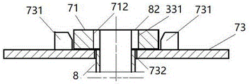
The power head 3 is arranged in front of the mast 2 and is respectively arranged on two guide rails of the mast 2 through two guide frames 34 of the reduction box 31; the guide frame 34 of the power head 3 is fixedly arranged at the left upper part and the right upper part of the rear side of the reduction box 31; the guide protective cylinders 35 are respectively and fixedly arranged on the outer sides of the two guide frames 34; the butt joint 33 is fixedly arranged at the lower end of the output shaft 32 of the power head; sequentially adding a plurality of sections of drill rods 8 and external drill rods below the butt joint 33, and locking an upper joint 82 of the drill rod 8 and the butt joint 33, a lower joint 83 of the drill rod 8 above and an upper joint 82 of the drill rod 8 below until the last section of drill rod 8 and the external drill bit in the forward rotation process of the power head 3; the power head 3 is operated to move downwards along the two guide rails of the mast 2, and the multiple sections of drill rods 8 and the external drill rods connected with the butt joint 33 sequentially pass through the bottom flange ring 211 of the bottom section mast 21, the inner cavity of the slewing reducer 6 and the base plate through hole 732 and then enter the bottom layer to drill to the hole forming depth required by the design.
The lifting oil cylinder 4 is arranged in a mode of penetrating through two guide pile casings 35 of the power head 3, and the cylinder casing end and the piston rod of the lifting oil cylinder are hinged with the bottom of each guide pile casing 35 and mast side lug seats 215 on two sides of the bottom section mast 21. The lifting oil cylinder 4 adopts a multi-section telescopic hydraulic cylinder type. Therefore, the travel requirement that the power head moves up and down along the guide rail of the mast is effectively met, and the low-clearance drilling machine is guaranteed to reach the hole forming depth required by the design.
The slewing reducer 6 is fixedly mounted on the lower end face of the bottom flange ring 211 of the bottom section mast 21 of the mast 2.
The backing plate 73 of the drill rod dismounting device is fixedly arranged on the rotary ring on the lower end face of the rotary speed reducer 6, and the four guide blocks 731 of the backing plate are positioned in the inner cavity of the rotary speed reducer 6. When the rotation reducer 6 is driven by external power, the backing plate 73 rotates together with the rotation ring of the rotation reducer 6. The four guide blocks 731 of the backing plate 73 are arranged in a rectangular arrangement on the end surface outside the through-hole thereof.
After the multiple sections of drill rods 8 reach the hole forming depth required by the design along with the drill bit 9, the power head 3 is closed to stop the multiple sections of drill rods 8 from rotating forward, the inner bayonet 712 of the short fork plate 71 is inserted into the joint notch 331 of the upper joint 82 of the lower section of drill rod 8 in alignment with the joint notch 331, and the short fork plate passes through the inner cavity of the slewing reducer 6 and then is placed in the area surrounded by the four guide blocks 731 on the backing plate 73 to lock the lower section of drill rod 8; the docking head 33 is locked by inserting the inner bayonet 712 of the long fork 72 in alignment with the adaptor slot 331 of the docking head 33 of the powerhead 3 and placing its handle 725 at the upper end face of the bottom flange ring 211 of the bottom section mast 21 of the mast 2. The thickness of the short fork plate 71 is greater than the height of the four guide blocks 731 of the backing plate 73. In this way, it is ensured that the short fork plate 71 effectively locks the section of drill rod 8 below when the slewing reducer 6 is rotated in the reverse direction.
The utility model discloses it is convenient and characteristics such as the pore-forming is reliable that self-walking rig has removal facility, simple structure, butt joint dismantlement, realizes swift drilling, stirring construction in the construction area that high restriction and surrounding environment are limited, improves the operating efficiency of the regional bored concrete pile construction of low headroom and ground reinforcement processing.
Without deviating from the general concept of the present invention, the present invention can be changed and improved, and also belong to the protection scope of the present invention as long as the same or equivalent elements of the present invention are formed.
Claims (4)
1. The utility model provides a from walking rig, includes crawler chassis (1), mast (2), unit head (3), lift cylinder (4), two vaulting poles (5), slewing reducer (6), drilling rod dismounting device, multisection have drilling rod (8) of top connection (82) and lower clutch (83), drill bit (9) that contain top connection (82), wherein:
the crawler chassis (1) comprises a chassis support (11) comprising a front end support (112), two upper supports (115), four corner supports (113) and four side supports (114), four connecting rods (12), four extending arms (13) and four supporting legs (14);
the mast (2) comprises a bottom section mast (21) comprising a bottom flange ring (211), a mast lower support (212), two lower guide rails (213) and a mast side lug seat (215), and an upper mast (21 ') comprising two upper guide rails (213');
the power head (3) comprises a reduction gearbox (31), an output shaft (32), a butt joint (33) with a joint notch (331) and right-handed conical external threads, two guide frames (34) and two guide protective cylinders (35) which are respectively positioned at the rear end part of the reduction gearbox;
the drill rod dismounting device comprises a short fork plate (71) with an inner bayonet (712), a long fork plate (72) with an inner bayonet (712) and a handle (725), and a backing plate (73) with four guide blocks (731);
the upper joint (82) of the drill rod (8) comprises a joint notch (331) and a right-hand conical external thread; the lower joint (83) of the drill rod (8) comprises a joint notch (331) and a right-handed conical internal thread;
the upper joint (82) of the drill bit (9) comprises a joint notch (331) and a right-handed conical external thread;
the method is characterized in that:
the chassis support (11) of the crawler chassis (1) is a rectangular frame component; the front end support (112) is arranged in the center of the front end part of the chassis support (11); the upper support (115) is arranged on the upper end surface of the chassis support (11) in a bilaterally symmetrical manner; the corner supports (113) are arranged at four corners of the chassis support (11); the side supports (114) are arranged on the left side surface and the right side surface of the chassis support (11) in a two-group mode; the extension arms (13) are connected with the chassis support (11) in a mode of respectively arranging a front side and a rear side, one end of each extension arm is respectively hinged to each corner support (113) of the chassis support (11), and the other end of each extension arm is fixedly provided with a supporting leg (14); the connecting rod (12) is respectively hinged with each side support (114) of the chassis bracket (11) and each extending arm fork seat (131) of each extending arm (13);
the mast (2) is fixedly arranged in front of the crawler chassis (1) and is hinged with the front end support (112) of the chassis support (11) through a mast lower support (212) of the bottom section mast (21); the upper mast (21') is fixedly arranged above the bottom section mast (21); after the bottom section mast (21) and the upper mast (21 ') are butted, a lower guide rail (213) and an upper guide rail (213 ') of the bottom section mast (21) and the upper mast (21 ') form a guide rail of the mast (2); the bottom flange ring (211) of the bottom section mast (21) is vertically arranged at the bottom of the bottom section mast;
the support rods (5) are arranged on two sides of the bottom section mast (21) and are respectively hinged with the side support (25) of the bottom section mast (21) and the two upper supports (115) of the chassis support (11);
the power head (3) is arranged in front of the mast (2) and is respectively arranged on two guide rails of the mast (2) through two guide frames (34) of the reduction gearbox (31); a guide frame (34) of the power head (3) is fixedly arranged above the left side and the right side of the rear side of the reduction box (31); the guide protective cylinders (35) are respectively and fixedly arranged at the outer sides of the two guide frames (34); the butt joint (33) is fixedly arranged at the lower end of an output shaft (32) of the power head; a plurality of sections of drill rods (8) and an external drill bit are sequentially additionally connected below the butt joint (33), and an upper joint (82) of the drill rod (8) and the butt joint (33), a lower joint (83) of the drill rod (8) above the butt joint and an upper joint (82) of the drill rod (8) below the butt joint, and the drill rod (8) up to the last section are locked with the external drill bit in the forward rotation process of the power head (3); the operating power head (3) moves downwards along two guide rails of the mast (2), and a plurality of sections of drill rods (8) and external drill bits connected with the butt joint (33) sequentially penetrate through a bottom flange ring (211) of the bottom section mast (21), an inner cavity of the slewing reducer (6) and a base plate through hole (732) and then enter the bottom layer to drill to the hole forming depth required by the design;
the lifting oil cylinder (4) is respectively arranged in a mode of penetrating through two guide pile casings (35) of the power head (3), and a cylinder barrel end and a piston rod of the lifting oil cylinder are respectively hinged with the bottom of each guide pile casing (35) and mast side lug seats (215) on two sides of the bottom section mast (21);
the slewing reducer (6) is fixedly arranged on the lower end face of a bottom flange ring (211) of a bottom section mast (21) of the mast (2);
a backing plate (73) of the drill rod dismounting device is fixedly arranged on a rotary ring on the lower end face of the rotary speed reducer (6), and four guide blocks (731) of the backing plate are positioned in an inner cavity of the rotary speed reducer (6); the four guide blocks (731) of the backing plate (73) are arranged on the end surface outside the through hole in a rectangular arrangement mode;
after the multiple sections of drill rods (8) reach the hole forming depth required by the design along with the drill bit (9), closing the power head (3) to stop the forward rotation of the multiple sections of drill rods (8), inserting the inner bayonet (712) of the short fork plate (71) into the joint notch (331) of the upper joint (82) of the lower section of drill rods (8), placing the short fork plate in an area surrounded by four guide blocks (731) on the backing plate (73) after penetrating through the inner cavity of the slewing reducer (6), and locking the lower section of drill rods (8); the inner bayonet (712) of the long fork plate (72) is aligned with the joint notch (331) of the butt joint (33) of the power head (3) to be inserted, and the handle (725) of the long fork plate is placed at the upper end face of the bottom flange ring (211) of the bottom section mast (21) of the mast (2), so that the butt joint (33) is locked.
2. The self-propelled drilling machine according to claim 1, characterized in that two, or three, spreader-arm prongs (131) of the extension arm (13) are provided.
3. Self-propelled drilling machine according to claim 1, characterized in that the lift cylinder (4) is in the form of a multi-joint telescopic cylinder.
4. The self-walking drill rig according to claim 1, characterized in that the thickness of the short fork plate (71) is larger than the height of the four guide blocks (731) of the tie plate (73).
Priority Applications (1)
| Application Number | Priority Date | Filing Date | Title |
|---|---|---|---|
| CN202220424605.3U CN217841509U (en) | 2022-03-01 | 2022-03-01 | Self-walking drilling machine |
Applications Claiming Priority (1)
| Application Number | Priority Date | Filing Date | Title |
|---|---|---|---|
| CN202220424605.3U CN217841509U (en) | 2022-03-01 | 2022-03-01 | Self-walking drilling machine |
Publications (1)
| Publication Number | Publication Date |
|---|---|
| CN217841509U true CN217841509U (en) | 2022-11-18 |
Family
ID=84009473
Family Applications (1)
| Application Number | Title | Priority Date | Filing Date |
|---|---|---|---|
| CN202220424605.3U Active CN217841509U (en) | 2022-03-01 | 2022-03-01 | Self-walking drilling machine |
Country Status (1)
| Country | Link |
|---|---|
| CN (1) | CN217841509U (en) |
Cited By (1)
| Publication number | Priority date | Publication date | Assignee | Title |
|---|---|---|---|---|
| CN114412353A (en) * | 2022-03-01 | 2022-04-29 | 上海广大基础工程有限公司 | A self-propelled drilling rig and its construction method |
-
2022
- 2022-03-01 CN CN202220424605.3U patent/CN217841509U/en active Active
Cited By (2)
| Publication number | Priority date | Publication date | Assignee | Title |
|---|---|---|---|---|
| CN114412353A (en) * | 2022-03-01 | 2022-04-29 | 上海广大基础工程有限公司 | A self-propelled drilling rig and its construction method |
| CN114412353B (en) * | 2022-03-01 | 2025-02-14 | 上海广大基础工程有限公司 | Self-propelled drilling rig and construction method thereof |
Similar Documents
| Publication | Publication Date | Title |
|---|---|---|
| CN110331936B (en) | Combined drilling bottom-expanding pile-planting construction method | |
| CN111608587B (en) | Construction system and method of hard rock drilling for interlocking piles in foundation pits in height-restricted areas | |
| CN119266207B (en) | A limited micro-space pile foundation construction method based on a multifunctional pile driver | |
| CN210530738U (en) | Pile system is planted in drilling in groups | |
| CN108755729A (en) | A kind of CFG pile foundations pile cover and pile body integrative construction device and method | |
| CN212477725U (en) | A pile driver with a split and combined type full pile guard | |
| RU2196203C1 (en) | Method of installing mounted equipment of berkut drill-pile driver | |
| CN114059524A (en) | Construction process of cast-in-situ bored pile in limited space | |
| CN114412353B (en) | Self-propelled drilling rig and construction method thereof | |
| CN207453902U (en) | A kind of full circle swinging all casing drill | |
| CN210509059U (en) | Group drilling processor unit | |
| CN113530476B (en) | A drill rod lifting and lowering device for down-the-hole hammer drilling process of rotary drilling rig | |
| CN202767878U (en) | Multifunctional all-hydraulic drill | |
| CN210530745U (en) | Combined drilling bottom-expanding pile-planting system | |
| CN117588159B (en) | Rectangular pile pore-forming equipment | |
| CN217001722U (en) | Drill rod disassembling device | |
| CN114109271B (en) | Barrel drill for rotary drilling rig | |
| CN212614533U (en) | Rotary drilling rig for fishing method construction | |
| CN215632834U (en) | Drill rod lifting and lowering device for drilling process of down-the-hole hammer of rotary drilling rig | |
| CN213596970U (en) | Low clearance type deep mixing pile machine | |
| CN210946865U (en) | Concrete-filled steel tube pile group suitable for narrow space | |
| CN117432352A (en) | A kind of static drilling root pile construction equipment | |
| CN210216546U (en) | Chain saw box pulling device of channel type cement soil wall cutting equipment | |
| CN114541390A (en) | Cast-in-place pile construction method | |
| CN210238501U (en) | Double-rotation ground anchor |
Legal Events
| Date | Code | Title | Description |
|---|---|---|---|
| GR01 | Patent grant | ||
| GR01 | Patent grant |