CN217833910U - Special circular frock of coming unstuck of copper bar - Google Patents
Special circular frock of coming unstuck of copper bar Download PDFInfo
- Publication number
- CN217833910U CN217833910U CN202222114948.2U CN202222114948U CN217833910U CN 217833910 U CN217833910 U CN 217833910U CN 202222114948 U CN202222114948 U CN 202222114948U CN 217833910 U CN217833910 U CN 217833910U
- Authority
- CN
- China
- Prior art keywords
- copper bar
- rod
- cutter
- plate
- fixing frame
- Prior art date
- Legal status (The legal status is an assumption and is not a legal conclusion. Google has not performed a legal analysis and makes no representation as to the accuracy of the status listed.)
- Active
Links
Images


Landscapes
- Sawing (AREA)
Abstract
The utility model relates to a special circular frock of coming unstuck of copper bar, it includes mount, elastic plate, circular cutter and regulation lever, set up and cut the hole of stepping down on the elastic plate, and install in the said mount; the circular cutter comprises an upper cutter and a lower cutter; the lower cutter is fixedly arranged in the fixing frame and is positioned below the elastic plate, and the cutting edge of the lower cutter extends into the cutting abdicating hole; the upper cutter is driven by the driving piece to descend and cut towards the cutting abdicating hole direction; the adjusting rod is positioned on the elastic plate and is connected with the fixed frame in a sliding way. The utility model discloses utilize circular cutter to cut simultaneously the upper and lower surface of copper bar, can also realize laborsaving, the efficient purpose to solve the technical problem who exists among the prior art.
Description
Technical Field
The utility model belongs to the technical field of the frock for glue is shelled to the copper bar and specifically relates to a special circular frock that comes unstuck of copper bar that can cut fast and two-sided is related to.
Background
The copper bar is a strip-shaped copper plate, the outer layer of the copper bar is wrapped with the rubber layer, and the rubber layer is peeled off as required before the copper bar is used, so that the copper bar is used and assembled. In actual production and processing, in order to provide processing convenience for subsequent processing, a round degumming (degumming is rubber layer stripping) operation is required. As shown in fig. 1, the rubber layer I on the copper bar Q is peeled off in a circular shape at a fixed point.
The stripping tool for processing the copper bar shown in fig. 1 is a device which is not provided in the market at present, and needs to be developed and improved on the basis of the existing stripping tool or device. However, the existing stripping tool is a stripping device as set forth in chinese patent publication No. CN 215473732U; the mucilage binding that shells that this scheme was expounded can't carry out upper and lower rubber layer simultaneously to the copper bar and peel off, also can't carry out peeling off of circular dress region glue film, all need artifical manual work to come unstuck the operation, and this is just prolonged single copper bar and is shelled long time of gluing, reduces to shell the machining efficiency who glues, and then increase cost.
Therefore, how to design and manufacture a special glue stripping tool on the basis of the existing tool to achieve the purpose of cutting the round shape of the specific point of the copper bar and stripping the rubber layer, and the technical problems that in the prior art, the processing efficiency is low, two sides cannot be stripped simultaneously and the like are solved.
SUMMERY OF THE UTILITY MODEL
For solving the technical problem that exists among the above-mentioned prior art, the utility model aims to provide a special circular frock of coming unstuck of copper bar that can be quick and laborsaving.
In order to achieve the above purpose, the utility model adopts the following technical scheme:
the utility model provides a special circular frock of coming unstuck of copper bar, it includes mount, elastic plate, circular cutter and adjusts the pole, wherein:
the elastic plate is provided with a cutting abdicating hole and is arranged in the fixed frame;
the circular cutter comprises an upper cutter and a lower cutter; the lower cutter is fixedly arranged in the fixing frame and positioned below the elastic plate, and the cutting edge of the lower cutter extends into the cutting abdication hole; the upper cutter is driven by the driving piece to descend towards the cutting abdicating hole for cutting;
the adjusting rod is positioned on the elastic plate and is connected with the fixed frame in a sliding way.
Further preferred is: the elastic plate comprises a plate body and an elastic piece, wherein:
the plate body is assembled in the fixing frame, and two ends of the plate body are inserted into the bouncing holes of the fixing frame;
the elastic piece is a fixed rod sleeved with a spring, the fixed rod penetrates through the fixed frame and extends into the through hole of the plate body, and two ends of the spring are respectively abutted between the fixed frame and the plate body.
Further preferred is: the fixing frame is a rectangular frame and comprises a top plate, a bottom plate and two side plates, wherein the two side plates are provided with strip-shaped holes, and the strip-shaped holes are the bouncing holes.
Further preferred is: the fixing frame is provided with a screw rod, the screw rod is arranged in parallel with the elastic plate and is driven by a motor, and a nut is assembled on the screw rod;
one end of the adjusting rod is connected with the nut and linked with the nut so as to drive the adjusting rod to slide and displace along the direction of the screw rod.
Further preferred is: a linear slide rail is arranged along the direction of the screw rod and is fixed on the fixed frame;
and a sliding block is slidably arranged on the linear sliding rail and is connected and linked with the nut.
Further preferred is: a scale is arranged along the direction of the screw rod and fixed on the elastic plate;
the starting end of the scale is arranged corresponding to the center of the cutting abdicating hole.
Further preferred is: the adjusting rod is located one side of the cutting yielding hole, and the scale is arranged corresponding to the adjusting rod.
Further preferably: the driving piece comprises a cylinder and a driving rod, wherein:
one end of the driving rod is hinged on the fixed frame, and the other end of the driving rod is connected with the output end of the air cylinder;
the cylinder is arranged close to the fixed frame;
the upper cutter is hinged on the driving rod to drive the upper cutter to press and cut.
Further preferably: the driving rod is obliquely arranged, the lower end of the driving rod is hinged with the fixing frame, and the higher end of the driving rod is connected and linked with the output end of the air cylinder.
After the technical scheme is adopted, compared with the background art, the utility model, have following advantage:
the utility model utilizes the circular cutter to simultaneously cut the upper and lower surfaces of the copper bar, thereby achieving the purpose of simultaneously degumming and improving the degumming efficiency; meanwhile, the utility model also designs a regulating rod which can be regulated in a sliding way, and the regulating rod is matched with the scale to measure and read the size of the copper bar, thereby further improving the convenience of measuring the size of the workpiece; and then, the cylinder is utilized to drive the driving rod, the circular cutter is driven, and the purposes of labor saving and high efficiency are achieved, so that the technical problem in the prior art is solved.
Drawings
Fig. 1 shows a copper bar processed by using the circular degumming tool special for the copper bar in the embodiment of the utility model;
fig. 2 is a first schematic structural view of the circular degumming tool special for copper bars in the embodiment of the present invention;
fig. 3 is a schematic structural diagram of the circular degumming tool special for the copper bar in the embodiment of the present invention;
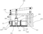
fig. 4 is the embodiment of the utility model provides an in the embodiment the special circular frock that comes unstuck of copper bar structure section sketch map.
The reference numbers in the drawings of the above specification are as follows:
q, copper bar, I, rubber layer, 110, bottom plate, 120, curb plate, 130, roof, 121, spring hole, 131, mount table, 210, plate body, 211, cut the hole of stepping down, 220, elastic component, 221, dead lever, 222, spring, 300, regulation pole, 310, motor, 320, lead screw, 330, nut, 340, linear slide rail, 350, slider, 410, go up the cutter, 420, down the cutter, 500, actuating lever, 510, cylinder, 600, scale.
Detailed Description
In order to make the objects, technical solutions and advantages of the present invention more clearly understood, the present invention is further described in detail below with reference to the accompanying drawings and embodiments. It should be understood that the specific embodiments described herein are for purposes of illustration only and are not intended to limit the invention.
In the present invention, it should be noted that the terms "upper", "lower", "left", "right", "vertical", "horizontal", "inner", "outer", etc. are all based on the orientation or position relationship shown in the drawings, and are only for convenience of description and simplification of the present invention, but do not indicate or imply that the device or element of the present invention must have a specific orientation, and thus, should not be construed as limiting the present invention.
Examples
The utility model provides a special circular frock of coming unstuck of copper bar, its copper bar Q that is used for specific length to carry out peeling off of specific shape with the rubber layer I of copper bar Q parcel, reach convenient, laborsaving, quick purpose, thereby promote machining efficiency, reduce the processing cost.
The special round degumming tool for the copper bar Q comprises a fixing frame, an elastic plate, a round cutter and an adjusting rod 300.
The fixing frame is a rectangular frame, and includes a top plate 130, a bottom plate 110 and two side plates 120, the two side plates 120 are parallel to each other and fixed at two ends of the bottom plate 110, and the top plate 130 is fixed on the two side plates 120. Specifically, the method comprises the following steps: the bottom plate 110 is a rectangular plate body which can have a certain thickness, so that stable support is provided, the two side plates 120 are identical in structure and symmetrically distributed, each side plate 120 is provided with a strip-shaped hole, each strip-shaped hole is a bouncing hole 121, the bouncing holes 121 are matched in position, the top plate 130 covers the bottom plate 110 and is connected with the side plates 120 to form a complete rectangular frame, the frame is vertically arranged on a processing table, and the vertical installation means that: the base plate 110 is placed or fixed on a processing table, which is a processing platform.
It should be noted that: the width of the bottom plate 110 (i.e. the length of the short side of the bottom plate 110) is greater than the width of the top plate 130 and either side plate 120, that is: the base plate 110 has a boss along its short side direction; the top plate 130 has a length greater than that of the bottom plate 110, i.e.: the top plate 130 has a mounting block 131 along the longitudinal direction of the bottom plate 110.
A linear slide rail 340 is fixed on the boss; the mounting table 131 provides a mounting location for the air cylinder 510.
The elastic plate includes a plate body 210 and an elastic member 220. The plate body 210 is rectangular, two convex blocks are arranged along the long side direction of the plate body, the two convex blocks are respectively positioned at two ends of the plate body 210, and the two convex blocks are respectively inserted into the bouncing holes 121 of the two side plates 120; a through-hole has been seted up on plate body 210, the position of through-hole can set up according to the demand, and the aperture of through-hole also peels off the glue film size according to copper bar Q needs and sets for, needs to notice: the aperture of the through hole is slightly larger than the size of the glue layer to be stripped of the copper bar Q; the through hole is a cutting abdicating hole 211, and the cutting abdicating hole 211 is arranged close to one side plate 120 of the fixing frame;
the side of the plate body 210 is provided with a scale 600, that is: the scale 600 is disposed along the long side of the plate 210 and above the boss of the bottom plate 110 of the fixing frame. The start end of the scale 600 corresponds to the center of the cutting abdicating hole 211, namely: one end of the scale 600 with the size of 0 corresponds to the center of the cutting abdicating hole 211, and the other end faces one side plate 120 of the fixing frame. The scale 600 is a linear scale with a division value of 0.1cm and a total length of 150cm.
It should be noted that: the plate 210 can move up and down along the direction of the bouncing hole 121.
The elastic member 220 is a fixing rod 221 sleeved with a spring 222, the fixing rod 221 passes through the fixing frame and extends into the through hole of the plate body 210, and two ends of the spring 222 respectively abut against the fixing frame and the plate body 210. Specifically, the method comprises the following steps: the fixing rod 221 is inserted from the bottom plate 110 of the fixing frame toward the top plate 130, one end of the fixing rod is clamped in the bottom plate 110, and the other end of the fixing rod extends into the through hole of the plate body 210, and it should be noted that the fixing rod 221 does not extend out of the through hole of the plate body 210. The two ends of the spring 222 are respectively pressed against the bottom plate 110 and the plate 210 of the fixing frame. When the plate 210 is displaced toward the bottom plate 110 of the fixing frame along the bouncing hole 121 due to the downward pressure, the plate 210 compresses the spring 222, and after the downward pressure disappears, the spring 222 is reset to push the plate 210 back to be reset.
It should be noted that: in order to improve the structural stability of the elastic plate, two elastic members 220 are disposed between the plate body 210 and the bottom plate 110 of the fixing frame, and the two elastic members 220 are distributed at intervals; in this embodiment, the two elastic members 220 are respectively located at two sides of the cutting abdicating hole 211.
The adjusting lever 300 is positioned on the elastic plate and is slidably connected with the fixing frame. The adjusting rod 300 is an L-shaped short straight rod and is positioned on the plate body 210; the adjusting rod 300 is disposed along the short side direction of the plate body 210 in the elastic plate, is located on the plate body 210, is driven by the screw rod 320, and is slidably displaced along the screw rod 320. Specifically, the method comprises the following steps: a screw 320 is arranged along the long side direction of the bottom plate 110 in the fixing frame, the screw 320 is positioned between the bottom plate 110 and the middle plate 210 of the elastic plate, the screw 320, the bottom plate 110 and the plate 210 are parallel to each other, one end of the screw 320 is connected with a motor 310 and is driven to rotate by the motor 310, the motor 310 is fixed on one side plate 120 of the fixing frame, a nut 330 is arranged on the screw 320, and the nut 330 is driven to slide and move along the axial direction of the screw 320 by the rotation of the screw 320; one end of the adjusting rod 300 is connected and linked with the nut 330 to drive the adjusting rod 300 to slide and displace along the direction of the screw rod 320, that is: the adjusting rod 300 is driven by the matching of a motor 310 and a screw rod 320 and slides and moves along the axial direction of the screw rod 320; it should be noted that: the scale 600 is disposed along the sliding direction of the adjustment lever 300, so that the specific position of the adjustment lever 300 is adjusted according to the size reading on the scale 600.
One side of the adjusting rod 300 facing the cutting abdicating hole 211 is a standard side, and the standard side is aligned with any reading line on the scale 600, so that the position can be accurately and conveniently judged, and the convenience and the accuracy of glue stripping are improved.
In order to further improve the stability of the sliding displacement of the adjusting lever 300, the adjusting lever 300 is further provided with a sliding mechanism; slide mechanism includes slider 350 and foretell linear slide rail 340, linear slide rail 340 sets up along the long limit direction of base in the fixing base, promptly: the linear slide rail 340 is parallel to the screw rod 320; the sliding block 350 is connected and linked with the nut 330 through a connecting rod, namely: when the nut 330 slides back and forth along the direction of the lead screw 320, the nut 330 drives the slider 350 to slide back and forth along the direction of the linear slide 340.
The circular cutters include an upper cutter 410 and a lower cutter 420; the lower cutter 420 is fixedly arranged in the fixing frame and is positioned below the elastic plate, and the cutting edge of the lower cutter 420 extends into the cutting abdicating hole 211; the upper cutter 410 is driven by the driving member to descend toward the cutting abdicating hole 211 for cutting. Specifically, the method comprises the following steps: the upper cutter 410 and the lower cutter 420 are both annular cutters; the lower cutter 420 has an upper annular blade and is fixed on the middle bottom plate 110 of the fixing frame, and the upper annular blade extends into the cutting abdicating hole 211; the upper cutter 410 has a lower annular blade, which is suspended above the lower cutter 420, and is driven by the driving member to descend toward the cutting abdicating hole 211 for cutting.
The driving part comprises an air cylinder 510 and a driving rod 500, one end of the driving rod 500 is hinged on the fixed frame, and the other end of the driving rod 500 is connected with the output end of the air cylinder 510; the cylinder 510 is arranged close to the fixed frame; the upper cutter 410 is hinged on the driving rod 500 to drive the upper cutter 410 to cut. The driving rod 500 is obliquely arranged, the lower end of the driving rod is hinged to the fixed frame, and the upper end of the driving rod is connected and linked with the output end of the air cylinder 510. Specifically, the method comprises the following steps: the cylinder 510 is fixed at the mounting table 131 of the top plate 130 in the fixing frame, and the output end of the cylinder 510 is arranged towards the top plate 130 of the fixing frame; the driving rod 500 is a straight rod which is obliquely arranged, the lower end of the driving rod is hinged with the fixed frame, the upper end of the driving rod is connected and linked with the output end of the air cylinder 510, and the upper cutter 410 penetrates through a through hole of the top plate 130 in the fixed frame to be hinged with the driving rod 500.
The working principle of the circular degumming tool special for the copper bar Q is as follows:
preparing a copper bar Q, wrapping the copper bar Q with a rubber layer I, and cutting a circular-ring-shaped cut for the rubber layer I at a positioning point by using a special circular-shaped degumming tool for the copper bar Q, so as to strip the rubber layer I, obtain a circular-shaped exposure area on the copper bar Q and match the subsequent use.
Placing a copper bar Q on an elastic plate, wherein one end of the copper bar Q is abutted against one side plate 120 in the fixing frame, the other end of the copper bar Q is abutted against the adjusting rod 300, adjusting the position of the adjusting rod 300 through sliding to be matched with the current copper bar Q, and reading the size of the copper bar Q (namely reading the distance from the center of the cutting abdicating hole 211 of the copper bar Q to the adjusting rod 300) for recording or subsequent use;
the cylinder 510 drives the upper cutter 410 to press downwards to cut the copper bar Q, and when the upper cutter is pressed downwards to cut, the upper cutter 410 is abutted against the copper bar Q to cut the rubber layer I on the upper surface of the copper bar Q; at the moment, the copper bar Q is abutted against the elastic plate, the plate body 210 in the elastic plate descends along the direction of the bounce hole 121 until the upper annular cutting edge of the lower cutter 420 extends out of the cutting abdicating hole 211 to cut the rubber layer I on the lower surface of the copper bar Q, and therefore the purpose of simultaneously cutting the upper surface and the lower surface is achieved;
after cutting, the upper cutter 410 is lifted and reset, at the moment, the downward pressure of the elastic plate disappears, the plate body 210 in the elastic plate is lifted and reset along the direction of the bounce hole 121 due to the reset force of the spring 222 in the elastic piece 220, so that the cutting edge of the lower cutter 420 is hidden, and the copper bar Q which is cut on two sides can be taken down;
and peeling the rubber layer I along the cutting cuts of the upper and lower cutters 420 to finally obtain the copper bar Q with the circular exposed areas on the upper and lower surfaces.
The above description is only for the preferred embodiment of the present invention, but the scope of the present invention is not limited thereto, and any changes or substitutions that can be easily conceived by those skilled in the art within the technical scope of the present invention should be covered by the present invention. Therefore, the protection scope of the present invention shall be subject to the protection scope of the claims.
Claims (9)
1. Special circular frock of coming unstuck of copper bar, its characterized in that: it includes mount, elastic plate, circular cutter and adjusts the pole, wherein:
the elastic plate is provided with a cutting abdicating hole and is arranged in the fixed frame;
the circular cutter comprises an upper cutter and a lower cutter; the lower cutter is fixedly arranged in the fixing frame and positioned below the elastic plate, and the cutting edge of the lower cutter extends into the cutting abdication hole; the upper cutter is driven by the driving piece to descend and cut towards the cutting abdicating hole direction;
the adjusting rod is positioned on the elastic plate and is connected with the fixed frame in a sliding way.
2. The special circular frock of coming unstuck of copper bar of claim 1, characterized in that: the elastic plate comprises a plate body and an elastic piece, wherein:
the plate body is assembled in the fixing frame, and two ends of the plate body are inserted into the bouncing holes of the fixing frame;
the elastic piece is a fixing rod sleeved with a spring, the fixing rod penetrates through the fixing frame and extends into the through hole of the plate body, and two ends of the spring are respectively abutted between the fixing frame and the plate body.
3. The special circular frock of coming unstuck of copper bar of claim 2, characterized in that: the fixing frame is a rectangular frame and comprises a top plate, a bottom plate and two side plates, wherein the two side plates are provided with strip-shaped holes, and the strip-shaped holes are the bouncing holes.
4. The special circular frock of coming unstuck of copper bar of claim 1, characterized in that: the fixing frame is provided with a screw rod, the screw rod is arranged in parallel with the elastic plate and is driven by a motor, and a nut is assembled on the screw rod;
one end of the adjusting rod is connected with the nut and linked with the nut so as to drive the adjusting rod to slide and displace along the direction of the screw rod.
5. The special circular frock of coming unstuck of copper bar of claim 4, characterized in that: a linear slide rail is arranged along the direction of the screw rod and is fixed on the fixed frame;
and a sliding block is slidably arranged on the linear sliding rail and is connected and linked with the nut.
6. The special circular frock of coming unstuck of copper bar of claim 4, characterized in that: a scale is arranged along the direction of the screw rod and fixed on the elastic plate;
the starting end of the scale is arranged at the center of the corresponding cutting abdicating hole.
7. The special circular frock of coming unstuck of copper bar of claim 6, characterized in that: the adjusting rod is located one side of the cutting yielding hole, and the scale is arranged corresponding to the adjusting rod.
8. The special circular frock of coming unstuck of copper bar of claim 1, characterized in that: the driving piece comprises a cylinder and a driving rod, wherein:
one end of the driving rod is hinged to the fixed frame, and the other end of the driving rod is connected with the output end of the air cylinder;
the cylinder is arranged close to the fixed frame;
the upper cutter is hinged on the driving rod to drive the upper cutter to press and cut.
9. The special circular frock of coming unstuck of copper bar of claim 8, characterized in that: the driving rod is obliquely arranged, the lower end of the driving rod is hinged with the fixing frame, and the higher end of the driving rod is connected and linked with the output end of the air cylinder.
Priority Applications (1)
| Application Number | Priority Date | Filing Date | Title |
|---|---|---|---|
| CN202222114948.2U CN217833910U (en) | 2022-08-11 | 2022-08-11 | Special circular frock of coming unstuck of copper bar |
Applications Claiming Priority (1)
| Application Number | Priority Date | Filing Date | Title |
|---|---|---|---|
| CN202222114948.2U CN217833910U (en) | 2022-08-11 | 2022-08-11 | Special circular frock of coming unstuck of copper bar |
Publications (1)
| Publication Number | Publication Date |
|---|---|
| CN217833910U true CN217833910U (en) | 2022-11-18 |
Family
ID=84014021
Family Applications (1)
| Application Number | Title | Priority Date | Filing Date |
|---|---|---|---|
| CN202222114948.2U Active CN217833910U (en) | 2022-08-11 | 2022-08-11 | Special circular frock of coming unstuck of copper bar |
Country Status (1)
| Country | Link |
|---|---|
| CN (1) | CN217833910U (en) |
-
2022
- 2022-08-11 CN CN202222114948.2U patent/CN217833910U/en active Active
Similar Documents
| Publication | Publication Date | Title |
|---|---|---|
| CN217833910U (en) | Special circular frock of coming unstuck of copper bar | |
| CN204454007U (en) | A kind of bar cutter clamping pay-off | |
| CN201656218U (en) | Line-cutting crimping machine | |
| CN211967625U (en) | Battery side cut device | |
| CN210758177U (en) | Automatic filament cutting belt device for packaging box filament belt mounting | |
| CN214976983U (en) | Stamping device for aluminum card slot | |
| CN212760590U (en) | Accurate side cut mould of auto parts | |
| CN214395492U (en) | Full-automatic slicing and rubberizing device | |
| CN115156903A (en) | Automatic moving cutter set assembling device for automatic razor head assembling line | |
| CN210710005U (en) | Automatic protective film cutting equipment | |
| CN209832499U (en) | Thermal cutting device | |
| CN209023278U (en) | A kind of automatic shearing foot transposition tape sticking device | |
| CN218699082U (en) | High-precision cutter mechanism for adhesive tape sticking machine | |
| CN219027616U (en) | Insulation paper edge trimming device | |
| CN219632343U (en) | Simple tailing cutting mechanism for punching machine | |
| CN215511160U (en) | Paper edge cutting machine with adjusting function | |
| CN217667605U (en) | Razor head automatic assembly line is with moving blade feed mechanism | |
| CN216262930U (en) | Trimming die for machining automobile shell | |
| CN213151245U (en) | Power line peeling device | |
| CN209896194U (en) | Adhesive tape cutting mechanism | |
| CN212858025U (en) | Special slicer of ornaments | |
| CN214561538U (en) | Cutting-off die | |
| CN217751612U (en) | Reciprocating type cutter for cutting sheet | |
| CN220052934U (en) | Glue core cutting riveting mechanism | |
| CN219358746U (en) | Copper flexible connector processing fixing device |
Legal Events
| Date | Code | Title | Description |
|---|---|---|---|
| GR01 | Patent grant | ||
| GR01 | Patent grant |