CN217823413U - Intelligent lamp belt control box - Google Patents
Intelligent lamp belt control box Download PDFInfo
- Publication number
- CN217823413U CN217823413U CN202221904512.7U CN202221904512U CN217823413U CN 217823413 U CN217823413 U CN 217823413U CN 202221904512 U CN202221904512 U CN 202221904512U CN 217823413 U CN217823413 U CN 217823413U
- Authority
- CN
- China
- Prior art keywords
- fixed
- control box
- installation
- limiting
- rod
- Prior art date
- Legal status (The legal status is an assumption and is not a legal conclusion. Google has not performed a legal analysis and makes no representation as to the accuracy of the status listed.)
- Active
Links
Images


Classifications
-
- Y—GENERAL TAGGING OF NEW TECHNOLOGICAL DEVELOPMENTS; GENERAL TAGGING OF CROSS-SECTIONAL TECHNOLOGIES SPANNING OVER SEVERAL SECTIONS OF THE IPC; TECHNICAL SUBJECTS COVERED BY FORMER USPC CROSS-REFERENCE ART COLLECTIONS [XRACs] AND DIGESTS
- Y02—TECHNOLOGIES OR APPLICATIONS FOR MITIGATION OR ADAPTATION AGAINST CLIMATE CHANGE
- Y02B—CLIMATE CHANGE MITIGATION TECHNOLOGIES RELATED TO BUILDINGS, e.g. HOUSING, HOUSE APPLIANCES OR RELATED END-USER APPLICATIONS
- Y02B20/00—Energy efficient lighting technologies, e.g. halogen lamps or gas discharge lamps
- Y02B20/40—Control techniques providing energy savings, e.g. smart controller or presence detection
Landscapes
- Fastening Of Light Sources Or Lamp Holders (AREA)
Abstract
The utility model relates to an intelligent lamp area control box, which comprises a wall, the right side fixed mounting of wall has the install bin, the right side laminating of install bin has the mounting panel, the left side of mounting panel is fixed with the fixed block, the right side of mounting panel is fixed with the control box body, be equipped with the fixed subassembly of the installation control box body of being convenient for on the install bin, be equipped with the spacing subassembly to fixed subassembly on the install bin, spacing subassembly includes the fixed plate, the fixed plate is fixed in the interior roof of install bin. This intelligent lamp area control box is equipped with fixed subassembly, and is spacing through carrying out the fixture block to the fixed block, further carries on spacingly through the gag lever post to the connecting rod to make the control box body fix on the right side of install bin, its operation process is simple convenient, is convenient for to the change of control box body, and it is more convenient to use, and the emergence that the control box body of in time changing the damage can effectively reduce the incident simultaneously, and the security performance is high.
Description
Technical Field
The utility model relates to an intelligent lamp area control box technical field specifically is intelligent lamp area control box.
Background
The intelligent lamp has the advantages of being soft, capable of being curled randomly, capable of being cut and connected in a delayed mode and the like, and is widely applied to decoration and illumination of buildings (indoor and outdoor decoration), bridges, roads, gardens, courtyards, floors, ceilings, furniture, automobiles, ponds, water bottoms, advertisements, signboards, signs and the like at present.
For example, a control box of the intelligent lamp band is disclosed in chinese patent (public number: CN 210345401U), and the control box of the intelligent lamp band includes a main body, a first connecting member and a second connecting member, where the first connecting member and the second connecting member are electrically connected to the main body, the first connecting member can be electrically connected to the LED lamp band in a detachable manner, the second connecting member can be electrically connected to an external power source to supply power to the LED lamp band, the main body is provided with a key and a control unit, the key is connected to the control unit, the control unit can respond to the operation of the key by a user to control and adjust the color and brightness of the LED lamp band, but the surface of the control box of the intelligent lamp band is worn or damaged after long-term use, which may cause the connection between the intelligent lamp band and the control box to be exposed, thereby easily causing a safety accident, and requiring timely replacement of the control box, but the device is not convenient for dismounting and replacement of the control box of the intelligent lamp band.
SUMMERY OF THE UTILITY MODEL
Not enough to prior art, the utility model provides an intelligent lamp area control box possesses the installation of being convenient for and dismantles advantages such as, has solved the problem that current equipment is not convenient for dismantle the change.
In order to achieve the above object, the utility model provides a following technical scheme: the intelligent lamp belt control box comprises a wall surface, wherein an installation box is fixedly installed on the right side of the wall surface, an installation plate is attached to the right side of the installation box, a fixed block is fixed on the left side of the installation plate, a control box body is fixed on the right side of the installation plate, a fixing assembly convenient for installation of the control box body is arranged on the installation box, and a limiting assembly for limiting the fixing assembly is arranged on the installation box;
furthermore, spacing subassembly includes the fixed plate, the fixed plate is fixed in the interior roof of install bin, the right side of fixed plate has the threaded rod of connecting through the bearing rotation, the right-hand member of threaded rod is fixed with driven awl tooth, the meshing has initiative awl tooth on the driven awl tooth, the top surface of initiative awl tooth is fixed with the dwang, the top of dwang is fixed with the runner, the surface threaded connection of threaded rod has the movable plate, the left side of movable plate is fixed with the stopper rod, the top surface of movable plate is fixed with the slider, sliding connection has the slide rail on the slider.
Furthermore, a limiting hole is formed in the right side of the installation box, and the fixing block penetrates through the limiting hole and is in clearance fit with the limiting hole.
Further, the right side of install bin top surface is fixed with the bearing, the surface of dwang is fixed mutually with the inner wall of bearing.
Further, the slide rail is fixed in the interior roof of install bin, the screw hole has been seted up to the side of movable plate, the threaded rod runs through the screw hole and rather than threaded connection.
Further, the fixed subassembly includes the telescopic link, the surface movable sleeve of telescopic link is equipped with the spring, the top of telescopic link is fixed with the fixture block, the left top surface of fixture block is fixed with the connecting rod.
Furthermore, the fixture block is U-shaped, and the spring is abutted between the bottom surface of the fixture block and the inner bottom wall of the installation box.
Furthermore, a limiting groove is formed in the right side of the connecting rod, the left end of the limiting rod is inserted into the limiting groove and in clearance fit with the limiting groove, a clamping groove is formed in the bottom surface of the fixing block, and the clamping block is inserted into the clamping groove and in clearance fit with the clamping groove.
Compared with the prior art, the utility model provides an intelligent lamp area control box possesses following beneficial effect: this intelligent lamp area control box is equipped with fixed subassembly, and is spacing through carrying out the fixture block to the fixed block, further carries on spacingly through the gag lever post to the connecting rod to make the control box body fix on the right side of install bin, its operation process is simple convenient, is convenient for to the change of control box body, and it is more convenient to use, and the emergence that the control box body of in time changing the damage can effectively reduce the incident simultaneously, and the security performance is high.
Drawings
Fig. 1 is a schematic structural view of the present invention;
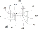
fig. 2 is a schematic structural view of the limiting assembly of the present invention;
fig. 3 is a right side view of the control box body of the present invention.
Fig. 4 is a schematic structural view of the fixing assembly of the present invention.
In the figure: the device comprises a control box body 1, a wall surface 2, an installation box 3, an installation plate 4, a fixed block 5, a limiting component 6, a fixed plate 601, a threaded rod 602, a driven bevel gear 603, a driving bevel gear 604, a rotating rod 605, a rotating wheel 606, a moving plate 607, a limiting rod 608, a sliding block 609, a sliding rail 610, a fixed component 7, a telescopic rod 701, a spring 702, a clamping block 703 and a connecting rod 704.
Detailed Description
The technical solutions in the embodiments of the present invention will be described clearly and completely with reference to the accompanying drawings in the embodiments of the present invention, and it is obvious that the described embodiments are only some embodiments of the present invention, not all embodiments. Based on the embodiments in the present invention, all other embodiments obtained by a person skilled in the art without creative work belong to the protection scope of the present invention.
Referring to fig. 1-3, the intelligent lamp band control box in this embodiment includes a wall surface 2, an installation box 3 is fixedly installed on the right side of the wall surface 2, an installation plate 4 is attached to the right side of the installation box 3, a fixed block 5 is fixed on the left side of the installation plate 4, a control box body 1 is fixed on the right side of the installation plate 4, a fixing component 7 convenient for installing the control box body 1 is arranged on the installation box 3, and a limiting component 6 limiting the fixing component 7 is arranged on the installation box 3.
It should be noted that, the bottom surface of control box body 1 is fixed with two terminals that are used for connecting intelligent lamp area, and fixed subassembly 7 can carry on spacingly to fixed block 5, further carries on spacingly to fixed subassembly 7 through spacing subassembly 6 to make control box body 1 fix on the right side of install bin 3, operation process is simple, convenient to use.
In addition, the limiting component 6 comprises a fixed plate 601, the fixed plate 601 is fixed on the inner top wall of the installation box 3, a threaded rod 602 rotatably connected through a bearing is arranged on the right side of the fixed plate 601, a driven bevel gear 603 is fixed on the right end of the threaded rod 602, a driving bevel gear 604 is meshed on the driven bevel gear 603, a rotating rod 605 is fixed on the top surface of the driving bevel gear 604, a rotating wheel 606 is fixed on the top end of the rotating rod 605, a moving plate 607 is connected to the outer surface of the threaded rod 602 through threads, a limiting rod 608 is fixed on the left side of the moving plate 607, a sliding block 609 is fixed on the top surface of the moving plate 607, and a sliding rail 610 is slidably connected to the sliding block 609.
It can be understood that the rotating wheel 606 is rotated to drive the rotating rod 605 to rotate, the driving bevel gear 604 is used for driving the driven bevel gear 603 to rotate, the threaded rod 602 is further driven to rotate, the threaded rod 602 is used for driving the moving plate 607 to move left and right, the fixing component 7 is further limited through the limiting rod 608, and therefore the purpose of fixing the control box body 1 is achieved.
Wherein, spacing hole has been seted up on the right side of install bin 3, and fixed block 5 runs through spacing hole and rather than clearance fit, and spacing hole plays supporting role simultaneously to fixed block 5 and plays spacing effect from top to bottom to fixed block 5, consequently only need control box body 1 fixed to fixed block 5 about controlling spacingly.
Meanwhile, a bearing is fixed on the right side of the top surface of the installation box 3, the outer surface of the rotating rod 605 is fixed with the inner wall of the bearing, and the rotating rod 605 can be limited to move up and down without influencing the rotation of the rotating rod 605.
In addition, the slide rail 610 is fixed on the inner top wall of the installation box 3, a threaded hole is formed in the side surface of the moving plate 607, the threaded rod 602 penetrates through the threaded hole and is in threaded connection with the threaded hole, and the slide block 609 and the slide rail 610 are arranged to prevent the moving plate 607 from being driven to rotate when the threaded rod 602 rotates, so that when the threaded rod 602 rotates, the moving plate 607 moves left and right on the outer surface of the threaded rod 602.
Referring to fig. 4, in order to limit the fixed block 5 left and right, the fixing assembly 7 includes a telescopic rod 701, a spring 702 is movably sleeved on an outer surface of the telescopic rod 701, a fixture block 703 is fixed at a top end of the telescopic rod 701, and a connecting rod 704 is fixed on a top surface of a left side of the fixture block 703.
It should be noted that, telescopic link 701 is including fixing the sleeve on the bottom wall in install bin 3, sliding connection has the slide bar on the telescopic inner wall, the slide bar reciprocates on the sleeve inner wall, the top surface of connecting rod 704 is fixed with the handle, it is more convenient that the handle makes connecting rod 704 remove the in-process, through pushing down the handle, can insert 3 inner chambers of install bin with fixed block 5, loosen the handle immediately, under the effect of spring 702, the right side of fixture block 703 can control fixed block 5 spacingly, thereby make control box body 1 fixed, operation process is simple and convenient, therefore, the clothes hanger is strong in practicability.
Wherein, fixture block 703 is the U font, and spring 702 butt is between the bottom surface of fixture block 703 and the bottom wall in install bin 3, and accessible spring 702 carries on spacingly with fixture block 703 automation to fixed block 5, reduces manual operation process, and is more practical.
Meanwhile, a limiting groove is formed in the right side of the connecting rod 704, the left end of the limiting rod 608 is inserted into the limiting groove and in clearance fit with the limiting groove, the limiting rod 608 is inserted into the limiting groove to limit the connecting rod 704 up and down, the device is more stable, a clamping groove is formed in the bottom surface of the fixing block 5, the clamping block 703 is inserted into the clamping groove and in clearance fit with the clamping groove, and the clamping block 703 is inserted into the clamping groove to limit the left and right of the fixing block 5.
The working principle of the embodiment is as follows: when a new control box body 1 needs to be replaced, the connecting rod 704 is pressed down through the handle, so that the clamping block 703 moves downwards, the fixing block 5 is aligned to the limiting hole on the right side of the installation box 3 and inserted into the inner cavity of the installation box 3, the handle is loosened, the clamping block 703 moves upwards under the action of the spring 702 at the moment, the right end of the clamping block 703 is inserted into the clamping groove, the rotating wheel 606 is rotated, the rotating rod 605 is driven to rotate through the rotating wheel 606, the driven bevel gear 603 is driven to rotate through the driving bevel gear 604, the threaded rod 602 is further driven to rotate, the moving plate 607 is driven to move leftwards through the threaded rod 602 until the limiting rod 608 is inserted into the limiting groove, and the replacement and installation process of the control box body 1 is completed.
It is noted that, herein, relational terms such as first and second, and the like may be used solely to distinguish one entity or action from another entity or action without necessarily requiring or implying any actual such relationship or order between such entities or actions. Also, the terms "comprises," "comprising," or any other variation thereof, are intended to cover a non-exclusive inclusion, such that a process, method, article, or apparatus that comprises a list of elements does not include only those elements but may include other elements not expressly listed or inherent to such process, method, article, or apparatus. Without further limitation, an element defined by the phrase "comprising a … …" does not exclude the presence of another identical element in a process, method, article, or apparatus that comprises the element.
Although embodiments of the present invention have been shown and described, it will be appreciated by those skilled in the art that changes, modifications, substitutions and alterations can be made in these embodiments without departing from the principles and spirit of the invention, the scope of which is defined in the appended claims and their equivalents.
Claims (7)
1. Intelligent lamp area control box, including wall (2), its characterized in that: an installation box (3) is fixedly installed on the right side of the wall surface (2), an installation plate (4) is attached to the right side of the installation box (3), a fixed block (5) is fixed on the left side of the installation plate (4), a control box body (1) is fixed on the right side of the installation plate (4), a fixed assembly (7) convenient for installation of the control box body (1) is arranged on the installation box (3), and a limiting assembly (6) for limiting the fixed assembly (7) is arranged on the installation box (3);
in addition, spacing subassembly (6) are including fixed plate (601), the interior roof of install bin (3) is fixed in fixed plate (601), the right side of fixed plate (601) has threaded rod (602) of rotating the connection through the bearing, the right-hand member of threaded rod (602) is fixed with driven awl tooth (603), the meshing has initiative awl tooth (604) on driven awl tooth (603), the top surface of initiative awl tooth (604) is fixed with dwang (605), the top of dwang (605) is fixed with runner (606), the surface threaded connection of threaded rod (602) has movable plate (607), the left side of movable plate (607) is fixed with spacing pole (608), the top surface of movable plate (607) is fixed with slider (609), sliding connection has slide rail (610) on slider (609).
2. The smart light strip control box of claim 1, wherein: the right side of the installation box (3) is provided with a limiting hole, and the fixing block (5) penetrates through the limiting hole and is in clearance fit with the limiting hole.
3. The smart light strip control box of claim 1, wherein: the right side of install bin (3) top surface is fixed with the bearing, the surface of dwang (605) is fixed mutually with the inner wall of bearing.
4. The smart light strip control box of claim 1, wherein: the sliding rail (610) is fixed on the inner top wall of the installation box (3), a threaded hole is formed in the side face of the moving plate (607), and the threaded rod (602) penetrates through the threaded hole and is in threaded connection with the threaded hole.
5. The smart light strip control box of claim 1, wherein: the fixing component (7) comprises an expansion rod (701), a spring (702) is movably sleeved on the outer surface of the expansion rod (701), a clamping block (703) is fixed at the top end of the expansion rod (701), and a connecting rod (704) is fixed on the top surface of the left side of the clamping block (703).
6. A smart light strip control box according to claim 5, characterised in that: the fixture block (703) is U-shaped, and the spring (702) is abutted between the bottom surface of the fixture block (703) and the inner bottom wall of the installation box (3).
7. A smart light strip control box according to claim 5, characterised in that: the right side of the connecting rod (704) is provided with a limiting groove, the left end of the limiting rod (608) is inserted into the limiting groove and is in clearance fit with the limiting groove, the bottom surface of the fixing block (5) is provided with a clamping groove, and the clamping block (703) is inserted into the clamping groove and is in clearance fit with the clamping groove.
Priority Applications (1)
| Application Number | Priority Date | Filing Date | Title |
|---|---|---|---|
| CN202221904512.7U CN217823413U (en) | 2022-07-23 | 2022-07-23 | Intelligent lamp belt control box |
Applications Claiming Priority (1)
| Application Number | Priority Date | Filing Date | Title |
|---|---|---|---|
| CN202221904512.7U CN217823413U (en) | 2022-07-23 | 2022-07-23 | Intelligent lamp belt control box |
Publications (1)
| Publication Number | Publication Date |
|---|---|
| CN217823413U true CN217823413U (en) | 2022-11-15 |
Family
ID=83967860
Family Applications (1)
| Application Number | Title | Priority Date | Filing Date |
|---|---|---|---|
| CN202221904512.7U Active CN217823413U (en) | 2022-07-23 | 2022-07-23 | Intelligent lamp belt control box |
Country Status (1)
| Country | Link |
|---|---|
| CN (1) | CN217823413U (en) |
-
2022
- 2022-07-23 CN CN202221904512.7U patent/CN217823413U/en active Active
Similar Documents
| Publication | Publication Date | Title |
|---|---|---|
| CN217823413U (en) | Intelligent lamp belt control box | |
| CN217978639U (en) | LED street lamp easy to install and maintain | |
| CN217559670U (en) | Building lighting lamp with angle adjusting structure | |
| CN216591256U (en) | Novel lens applied to LED wall washer | |
| CN212986925U (en) | Environment-friendly LED spot lamp | |
| CN217928625U (en) | Outdoor garden lamp that waterproof nature is good | |
| CN211315995U (en) | Multi-functional gardens building landscape lamp | |
| CN113775987A (en) | LED intelligence lamps and lanterns convenient to clean lamp face | |
| CN220749881U (en) | Outdoor lamp mounting structure | |
| CN216591255U (en) | Remote-controllable LED strip-shaped track lamp | |
| CN220152667U (en) | Novel solar swimming pool lawn lamp | |
| CN211203875U (en) | Street lamp with adjustable irradiation angle | |
| CN216345711U (en) | Classroom lamp capable of preventing mosquitoes and expelling insects | |
| CN214306705U (en) | Rotatable landscape lamp for environmental art | |
| CN218626544U (en) | Novel lamp pole for urban illumination | |
| CN204042754U (en) | A kind of focusing type LED with waterproof effect | |
| CN220186655U (en) | Waterproof flame lamp | |
| CN210441039U (en) | Novel integrated shimmer photoelectric street lamp | |
| CN219735224U (en) | Telescopic dustproof illuminating lamp | |
| CN218095673U (en) | LED lamp with adjustable light irradiation range | |
| CN220340854U (en) | Intelligent signboard convenient for changing identification | |
| CN219640167U (en) | LED driving street lamp convenient to height-adjusting | |
| CN212178621U (en) | LED lamp with mosquito-proof worm structure | |
| CN219606817U (en) | LED garden lamp convenient to change light-emitting plate | |
| CN211083901U (en) | L ED street lamp convenient to maintain |
Legal Events
| Date | Code | Title | Description |
|---|---|---|---|
| GR01 | Patent grant | ||
| GR01 | Patent grant |