CN217816420U - Lamp for building decoration - Google Patents
Lamp for building decoration Download PDFInfo
- Publication number
- CN217816420U CN217816420U CN202221443268.9U CN202221443268U CN217816420U CN 217816420 U CN217816420 U CN 217816420U CN 202221443268 U CN202221443268 U CN 202221443268U CN 217816420 U CN217816420 U CN 217816420U
- Authority
- CN
- China
- Prior art keywords
- roof
- diapire
- connecting plate
- mounting
- lateral wall
- Prior art date
- Legal status (The legal status is an assumption and is not a legal conclusion. Google has not performed a legal analysis and makes no representation as to the accuracy of the status listed.)
- Active
Links
Images


Abstract
The utility model discloses a lamps and lanterns for architectural decoration, relate to an architectural decoration technical field, which comprises a roof, mounting panel and connecting plate, wherein the mounting panel is installed on the roof, the mounting panel bottom links together through elevating system and roof, install a pair of stand in the middle of the diapire of roof, the stand is kept away from and is installed the pivot in the lateral wall of roof, rotate on the middle outer wall of pivot and install the connecting plate, the connecting plate can overturn round the pivot, rotate on the one end lateral wall of connecting plate and install the actuating lever, the other end of actuating lever rotates and installs on the outer wall of carousel, the carousel rotates and installs in the mounting bracket, the mounting bracket is installed on the diapire of roof, and the drive shaft of carousel passes through the output shaft of drive belt and small-size motor and is in the same place, small-size motor installs on the diapire of roof, wherein the symmetry is installed a pair of light on the diapire of connecting plate, the light overturns along with the connecting plate, improve the interest of lamps and lanterns, can be used for the illumination, also can be used for the decoration.
Description
Technical Field
The utility model relates to an architectural decoration technical field specifically is a lamp for architectural decoration.
Background
The lamp is an appliance capable of transmitting light, distributing and changing light distribution of a light source, and comprises all parts except the light source, which are required for fixing and protecting the light source, and circuit accessories required by connection with a power supply.
At present, with the pursuit of higher living quality of people, the requirements on lighting equipment of rooms, corridors and bedrooms are higher and higher, the lighting effect and the decoration effect are achieved, but the interestingness of the existing lamp is poorer.
Disclosure of Invention
To the problem that exists among the prior art, the utility model aims to provide a lamp for architectural decoration, the interest is stronger.
In order to achieve the above object, the utility model provides a following technical scheme: including the roof, mounting panel and connecting plate, wherein the mounting panel is installed on the roof, install elevating system on the diapire of mounting panel, elevating system's bottom and roof link together, install a pair of stand in the middle of the diapire of roof, install the pivot in the lateral wall that the roof was kept away from to the stand, rotate on the middle outer wall of pivot and install the connecting plate, the connecting plate can overturn round the pivot, rotate on the one end lateral wall of connecting plate simultaneously and install the actuating lever, the other end of actuating lever rotates and installs on the outer wall of carousel, the carousel rotates and installs in the mounting bracket, the mounting bracket is installed on the diapire of roof, and the drive shaft of carousel passes through drive belt and small motor's output shaft and links together, small motor installs on the diapire of roof, wherein the symmetry installs a pair of light on the diapire of connecting plate.
As a further aspect of the present invention: elevating system includes actuating lever, lead screw and slider, and wherein the one end of actuating lever is rotated and is installed on the roof of roof, and the other end of actuating lever is rotated and is installed on the diapire of slider, and slider slidable mounting is on the diapire of mounting panel to the lead screw is installed to the internal thread of slider, and the lead screw rotates and installs in the inside of support frame, and the support frame is installed on the diapire of mounting panel.
As a further aspect of the present invention: the top plate is far away from and rotates on the one side diapire of carousel and installs the connecting rod, and the other end of connecting rod rotates and installs on the roof that rotates the seat to the connecting plate has seted up multiunit installation screw on being close to one side roof of connecting rod, rotates the seat and passes through mounting bolt to be connected in the installation screw, wherein has seted up multiunit mounting hole in the lateral wall of stand, and the center of mounting hole is on same plumb line.
As a further aspect of the present invention: the connecting rod includes dead lever and carriage release lever, and wherein the dead lever rotates and installs on the diapire of roof, and the inner chamber has been seted up in the lateral wall that the roof was kept away from to the dead lever, and slidable mounting has the slide in the inner chamber, and a lateral wall mounting that the roof was kept away from to the slide has the carriage release lever, and the other end of carriage release lever stretches out from the lateral wall of inner chamber, and the end that stretches out of carriage release lever rotates and installs on the lateral wall of rotating the seat to a lateral wall mounting that the carriage release lever was kept away from to the slide has connecting spring, and connecting spring's the other end links together with the roof of inner chamber.
As a further aspect of the present invention: the lifting mechanisms are provided with two groups, the screw rods in the two groups of lifting mechanisms are fixedly connected together at one end close to each other, the thread directions of the two groups of screw rods are opposite, one group of screw rods extends out of the side wall of the supporting frame, and the extending ends of the screw rods are connected with a crank.
As a further aspect of the present invention: the lamp is characterized in that a lampshade is arranged on the outer side of the illuminating lamp, a connecting spiral ring is installed on the top wall of the lampshade, an annular screw hole is formed in the bottom wall of the connecting plate and located on the outer side of the illuminating lamp, and the lampshade is installed in the annular screw hole through a connecting spiral ring bolt.
Due to the adoption of the technical scheme, the utility model discloses following superiority has: the utility model discloses a light is installed in the bottom of connecting plate, and the one end of connecting plate is passed through the actuating lever and is linked together with the carousel, drives the carousel through small-size motor and rotates in the course of the work, drives the actuating lever cycle and reciprocates to it overturns about driving the connecting plate, wherein a pair of light is installed to the symmetry on the diapire of connecting plate, and the light overturns along with the connecting plate, improves the interest of lamps and lanterns, can be used for the illumination, also can be used to decorate, and the practicality is stronger.
Drawings
Fig. 1 is a schematic structural diagram of the present invention.
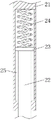
Fig. 2 is a schematic diagram of the lifting mechanism of the present invention.
Fig. 3 is a schematic view of the connecting rod structure of the present invention.
Fig. 4 is a schematic view of a part of the connection plate of the present invention.
As shown in the figure: 1. the device comprises a top plate, 2, a mounting plate, 3, a connecting plate, 4, a stand column, 5, a rotating shaft, 6, a lighting lamp, 7, a lampshade, 8, a rotary table, 9, a driving rod, 10, a small motor, 11, a driving belt, 12, a connecting rod, 13, a rotating seat, 14, a connecting spiral ring, 15, a mounting hole, 16, a driving rod, 17, a lead screw, 18, a sliding block, 19, a supporting frame, 20, a crank, 21, a fixing rod, 22, a moving rod, 23, a sliding plate, 24, a connecting spring, 25, an inner cavity, 26, an annular screw hole, 27 and a mounting screw hole.
Detailed Description
The technical solutions in the embodiments of the present invention will be described clearly and completely with reference to the accompanying drawings in the embodiments of the present invention, and it is obvious that the described embodiments are only some embodiments of the present invention, not all embodiments. Based on the embodiments in the present invention, all other embodiments obtained by a person skilled in the art without creative work belong to the protection scope of the present invention.
Please refer to fig. 1-4, in the embodiment of the utility model, a lamp for architectural decoration, including roof 1, mounting panel 2 and connecting plate 3, wherein mounting panel 2 is installed on the roof, install elevating system on mounting panel 2's the diapire, elevating system's bottom and roof 1 link together, install a pair of stand 4 in the middle of roof 1's the diapire, stand 4 is kept away from and is installed pivot 5 in the lateral wall of roof 1, it installs connecting plate 3 to rotate on the middle outer wall of pivot 5, connecting plate 3 can overturn round pivot 5, it installs actuating lever 9 to rotate on connecting plate 3's the one end lateral wall simultaneously, the other end of actuating lever 9 rotates and installs on carousel 8's outer wall, carousel 8 rotates and installs in the mounting bracket, the mounting bracket is installed on roof 1's diapire, and carousel 8's drive shaft passes through drive belt 11 and small motor 10's output shaft and is in the same place, small motor 10 installs on roof 1's diapire, it rotates to drive carousel 8 through small motor 10, it reciprocates to drive actuating lever 9 cycle, thereby drive connecting plate 3 and overturn from top to bottom, wherein the symmetry installs a pair of light 6 on 3, light 6 is along with connection plate 3 upset, the improvement light's interest, attraction is stronger.
Referring to fig. 2, it can be seen that: elevating system includes actuating lever 16, lead screw 17 and slider 18, and wherein the one end of actuating lever 16 is rotated and is installed on the roof of roof 1, and the other end of actuating lever 16 is rotated and is installed on the diapire of slider 18, and slider 18 slidable mounting is on the diapire of mounting panel 2, and lead screw 17 is installed to the internal thread of slider 18, and lead screw 17 rotates the inside of installing at support frame 19, and support frame 19 is installed on the diapire of mounting panel 2, carries out horizontal migration through lead screw 17 drive slider 18, drives roof 1 through actuating lever 16 and carries out elevating movement.
Preferably, the lifting mechanisms are provided with two groups, the screw rods 17 in the two groups of lifting mechanisms are fixedly connected together at one end close to each other, the thread directions of the two groups of screw rods 17 are opposite, one group of screw rods 17 extends out of the side wall of the supporting frame 19, the extending end of each screw rod 17 is connected with a crank 20, and the two groups of screw rods 17 are driven by the crank 20 to synchronously rotate.
Specifically, roof 1 rotates on the one side diapire of keeping away from carousel 8 and installs connecting rod 12, the other end of connecting rod 12 rotates and installs on the roof of rotating seat 13, and set up multiunit installation screw 27 on connecting plate 3 is close to one side roof of connecting rod 12, it connects in installation screw 27 through construction bolt to rotate seat 13, carry out auxiliary connection to connecting plate 3 through connecting rod 12, reduce the bearing pressure of actuating lever 9, wherein seted up multiunit mounting hole 15 in the lateral wall of stand 4, the center of mounting hole 15 is on same plumb line, be convenient for adjust the mounted position of connecting plate 3, thereby change the initial angle of connecting plate 3, in the adjustment process, the right side end position of connecting plate 3 is inconvenient, it can to change the mounted position who rotates seat 13.
Preferably, the connecting rod 12 includes a fixing rod 21 and a moving rod 22, wherein the fixing rod 21 is rotatably installed on the bottom wall of the top plate 1, an inner cavity 25 is formed in a side wall of the fixing rod 21 far away from the top plate 1, a sliding plate 23 is slidably installed in the inner cavity 25, a moving rod 22 is installed on a side wall of the sliding plate 23 far away from the top plate 1, the other end of the moving rod 22 extends out of the side wall of the inner cavity 25, the extending end of the moving rod 22 is rotatably installed on the side wall of the rotating seat 13, a connecting spring 24 is installed on a side wall of the sliding plate 23 far away from the moving rod 22, the other end of the connecting spring 24 is connected with the top wall of the inner cavity 25, and the moving rod 22 is tensioned in an auxiliary manner through the connecting spring 24.
Preferably, the outside of light 6 is provided with lamp shade 7, installs on the roof of lamp shade 7 and connects spiral ring 14 to annular screw 26 has been seted up on the diapire of connecting plate 3, annular screw 26 is located the outside of light 6, lamp shade 7 is installed in annular screw 26 through connecting spiral ring 14 bolt, shelter from the protection to light 6, different patterns can be carved on the lamp shade 7 surface, be used for supplementary decoration, adopt the mounting means of bolt, it is more convenient to change, can be applicable to the user demand of different scenes.
Claims (6)
1. The utility model provides a lamps and lanterns for architectural decoration, includes roof (1), mounting panel (2) and connecting plate (3), its characterized in that: install mounting panel (2) on the roof, install elevating system on the diapire of mounting panel (2), elevating system's bottom links together with roof (1), install a pair of stand (4) in the middle of the diapire of roof (1), install pivot (5) in the lateral wall of roof (1) is kept away from in stand (4), rotate on the middle outer wall of pivot (5) and install connecting plate (3), connecting plate (3) can overturn round pivot (5), rotate on the one end lateral wall of connecting plate (3) simultaneously and install actuating lever (9), the other end of actuating lever (9) is rotated and is installed on the outer wall of carousel (8), carousel (8) are rotated and are installed in the mounting bracket, the mounting bracket is installed on the diapire of roof (1), and the drive shaft of carousel (8) passes through drive belt (11) and small motor (10) and is in the same place, small motor (10) are installed on the diapire of roof (1), wherein a pair of light (6) is installed to the symmetry on the diapire of connecting plate (3).
2. A light for architectural decoration according to claim 1, wherein: elevating system includes actuating lever (16), lead screw (17) and slider (18), and wherein the one end of actuating lever (16) is rotated and is installed on the roof of roof (1), and the other end of actuating lever (16) is rotated and is installed on the diapire of slider (18), slider (18) slidable mounting is on the diapire of mounting panel (2) to lead screw (17) are installed to the internal thread of slider (18), and lead screw (17) are rotated and are installed in the inside of support frame (19), and the support frame (19) are installed on the diapire of mounting panel (2).
3. A light for architectural decoration according to claim 1, wherein: rotating on one side diapire that carousel (8) was kept away from in roof (1) and installing connecting rod (12), the other end of connecting rod (12) is rotated and is installed on the roof that rotates seat (13), and set up multiunit installation screw (27) on connecting plate (3) are close to one side roof of connecting rod (12), rotate seat (13) and connect in installation screw (27) through construction bolt, wherein seted up multiunit mounting hole (15) in the lateral wall of stand (4), the center of mounting hole (15) is on same plumb line.
4. A light for architectural decoration according to claim 3, wherein: connecting rod (12) are including dead lever (21) and carriage release lever (22), wherein dead lever (21) rotate to be installed on the diapire of roof (1), inner chamber (25) have been seted up in a lateral wall that roof (1) was kept away from in dead lever (21), sliding mounting has slide (23) in inner chamber (25), a lateral wall mounting that roof (1) was kept away from in slide (23) has carriage release lever (22), the other end of carriage release lever (22) stretches out from the lateral wall of inner chamber (25), the end that stretches out of carriage release lever (22) rotates to be installed on the lateral wall of rotating seat (13), and a lateral wall mounting that carriage release lever (22) was kept away from in slide (23) has connecting spring (24), the other end of connecting spring (24) and the roof of inner chamber (25) link together.
5. A light for architectural decoration according to claim 2, wherein: the lifting mechanisms are provided with two groups, lead screws (17) in the two groups of lifting mechanisms are mutually close to one end and fixedly connected together, the thread directions of the two groups of lead screws (17) are opposite, one group of lead screws (17) extend out of the side wall of the supporting frame (19), and the extending ends of the lead screws (17) are connected with a crank (20).
6. A light for architectural decoration according to claim 1, wherein: the lamp is characterized in that a lampshade (7) is arranged on the outer side of the illuminating lamp (6), a connecting spiral ring (14) is installed on the top wall of the lampshade (7), an annular screw hole (26) is formed in the bottom wall of the connecting plate (3), the annular screw hole (26) is located on the outer side of the illuminating lamp (6), and the lampshade (7) is installed in the annular screw hole (26) through the connecting spiral ring (14) in a bolt mode.
Priority Applications (1)
| Application Number | Priority Date | Filing Date | Title |
|---|---|---|---|
| CN202221443268.9U CN217816420U (en) | 2022-06-10 | 2022-06-10 | Lamp for building decoration |
Applications Claiming Priority (1)
| Application Number | Priority Date | Filing Date | Title |
|---|---|---|---|
| CN202221443268.9U CN217816420U (en) | 2022-06-10 | 2022-06-10 | Lamp for building decoration |
Publications (1)
| Publication Number | Publication Date |
|---|---|
| CN217816420U true CN217816420U (en) | 2022-11-15 |
Family
ID=83989573
Family Applications (1)
| Application Number | Title | Priority Date | Filing Date |
|---|---|---|---|
| CN202221443268.9U Active CN217816420U (en) | 2022-06-10 | 2022-06-10 | Lamp for building decoration |
Country Status (1)
| Country | Link |
|---|---|
| CN (1) | CN217816420U (en) |
-
2022
- 2022-06-10 CN CN202221443268.9U patent/CN217816420U/en active Active
Similar Documents
| Publication | Publication Date | Title |
|---|---|---|
| CN112325177A (en) | Household LED lamp with multiple light sources and adjustable illumination range | |
| CN217816420U (en) | Lamp for building decoration | |
| CN209744165U (en) | Square combination formula projecting lamp of 6 heads convenient to adjust luminance | |
| CN209325495U (en) | A kind of multiple groups are spliced to follow stage lighting automatically | |
| CN210241293U (en) | Projection angle adjusting device of projection lamp | |
| CN213299791U (en) | Automatically adjustable garden lamp | |
| CN211680800U (en) | Automatic assembling mechanism for LED ceiling lamp lens | |
| CN112178543A (en) | LED lamp with adjustable irradiation angle | |
| CN220205644U (en) | Liftable LED lamps and lanterns for decoration | |
| CN209569654U (en) | A kind of luminous energy wisdom street lamp for two-way highway | |
| CN112113169A (en) | Lamp hiding device and embedded lamp | |
| CN220892120U (en) | Adjustable lamplight mounting bracket | |
| CN203336353U (en) | Energy saving type efficient stage follow spot | |
| CN217714687U (en) | Multi-angle LED wall lamp | |
| CN209431205U (en) | Stage performance lamps and lanterns | |
| CN214369968U (en) | Outdoor lamp mounting base plate | |
| CN215174792U (en) | Ceramic lampshade | |
| CN214332433U (en) | Animation rendering lamp structure | |
| CN220229009U (en) | Automatic lifting device for crystal pendant lamp | |
| CN213065785U (en) | Make things convenient for illumination lamps and lanterns of dismouting | |
| CN219300600U (en) | Lamp for indoor lighting atmosphere creation | |
| CN109539200A (en) | A kind of LED illuminating lamp lamp bracket | |
| CN219530730U (en) | Landscape pillar lamp structure | |
| CN217875522U (en) | Make things convenient for outdoor projecting lamp of dismouting maintenance | |
| CN213065808U (en) | Lamp hiding device and embedded lamp |
Legal Events
| Date | Code | Title | Description |
|---|---|---|---|
| GR01 | Patent grant | ||
| GR01 | Patent grant |