CN217804043U - Computer dust collecting equipment - Google Patents
Computer dust collecting equipment Download PDFInfo
- Publication number
- CN217804043U CN217804043U CN202222773370.1U CN202222773370U CN217804043U CN 217804043 U CN217804043 U CN 217804043U CN 202222773370 U CN202222773370 U CN 202222773370U CN 217804043 U CN217804043 U CN 217804043U
- Authority
- CN
- China
- Prior art keywords
- dust
- dust collecting
- collar
- computer
- suction hood
- Prior art date
- Legal status (The legal status is an assumption and is not a legal conclusion. Google has not performed a legal analysis and makes no representation as to the accuracy of the status listed.)
- Active
Links
Images


Abstract
The utility model provides a computer dust collecting equipment, which comprises a housing, the dust collection chamber has been seted up in the casing, casing one end is equipped with the negative-pressure pump, and the other end is equipped with the dust absorption pipe, dust absorption pipe and negative-pressure pump all communicate with the dust collection chamber, dust absorption pipe one end is equipped with the suction hood, the connection can be dismantled to the suction hood lower extreme is equipped with the collar, the collar lower extreme is equipped with the brush hair, brush hair fixed connection sets up on the collar, be equipped with the vibrator on the suction hood, the vibrator is connected with the collar cooperation, starts the negative-pressure pump, cleans through the brush hair, through suction hood suction dust, and this equipment passes through the not hard up dust of brush hair and adheres to, then directly with dust suction and collect, easy operation and efficiency far above artifical manual cleaning, and the brush hair can vibrate automatically, further increase and clean the ability, improve dust collection efficiency.
Description
Technical Field
The utility model relates to a computer protection technology field, in particular to computer dust collecting equipment.
Background
The computer is commonly called computer, is an electronic computing machine for high-speed computing, can run according to programs, automatically processes modern intelligent electronic equipment of mass data at high speed, is incorporated into the life of people at the present of information age, and is widely applied to the life and work of people.
The computer can generate heat during working, the overhigh heat can overheat the computer, the operation efficiency of the computer is influenced, the computer can also be caused to have faults, and even potential safety hazards such as circuit fire and the like occur.
For guaranteeing the computer steady operation, need timely remove dust to the computer inside, but computer inner structure is complicated relatively, it is also very loaded down with trivial details affairs to have led to remove dust, generally carry out dust removal during operation, need dismantle inside equipment earlier, then the manual work is held the brush and is cleared up the dust that adheres to on quick-witted case shell and each equipment a bit, sweep the dust a bit, this process is very loaded down with trivial details, and the time spent is longer, dust collection efficiency is not high, and can cause computer equipment's damage at the in-process of dismouting, cause other losses, operating personnel only relies on simple brush to clean simultaneously, run into the dust of stubborn adherence on computer equipment, need frequent cleaning repeatedly just can sweep the dust, the inefficiency of manual dust removal, and the dust that cleans is difficult for collecting, so carry out computer dust collecting equipment's innovative design to this condition now.
SUMMERY OF THE UTILITY MODEL
Based on this, utility model's purpose is in order to solve among the prior art, when removing dust to the computer inside, cleans through simple brush is artifical, leads to the dust collection efficiency low, and the difficult problem of collecting of dust.
The utility model provides a computer dust collecting equipment, wherein, which comprises a housing, the dust collection chamber has been seted up in the casing, casing one end is equipped with the negative pressure pump, and the other end is equipped with the dust absorption pipe, the dust absorption pipe with the negative pressure pump all communicates with the dust collection chamber, dust absorption pipe one end is equipped with the suction hood, the connection can be dismantled to the suction hood lower extreme is equipped with the collar, the collar lower extreme is equipped with the brush hair, brush hair fixed connection sets up on the collar, be equipped with the vibrator on the suction hood, the vibrator with the collar cooperation is connected, starts the negative pressure pump, cleans through the brush hair, through suction hood suction dust.
The utility model provides a computer dust collecting equipment, in practical application, the suction and the guide of dust absorption pipe and suction hood that provide through the negative pressure pump, direct with the inside dust suction of computer, with the brush hair cooperation, the brush hair cleans the dust on the equipment, make the dust of adhering to on each equipment of computer not hard up, then by the direct suction of suction hood, the operating procedure has been reduced, it is more convenient to make to remove dust, it is more efficient, and need not dismantle the equipment in the computer completely, reduce the possibility that equipment damaged, and collect the dust of suction through the dust collection chamber, avoid the dust in a confused state of mind to fly, the handling convenience, the vibration ability that provides through the vibrator makes the brush hair keep the micro-vibration of high-frequency in addition, when cleaning computer equipment, sweep the dust that will adhere to on the computer more easily, do not need frequent cleaning repeatedly, further improve the efficiency of removing dust.
Computer dust collecting equipment, wherein, the suction hood with be equipped with solid fixed ring between the collar, gu fixed connection is equipped with the vibrating arm on the fixed ring, the suction hood on seted up with vibrating arm complex vibration groove, the vibrating arm with vibration groove sliding connection, the vibrator both ends all with the vibrating arm is connected, make solid fixed ring drive the collar vibration, make the brush hair keep fast-speed vibration, the convenience is cleaner with the dust clearance.
Computer dust collecting equipment, wherein, be equipped with the slide bar on the collar, be equipped with the stopper on the slide bar, solid fixed ring on seted up with the stopper with slide bar complex sliding tray, sliding tray one end be equipped with stopper complex inserted hole, the dismantlement and the installation of the collar of being convenient for, after the brush hair is impaired, be convenient for in time change the collar that has intact brush hair.
The computer dust removing equipment is characterized in that a dust collecting box is arranged in the dust collecting cavity, the dust collecting box is connected with the dust collecting cavity in a sliding mode, a dust guide pipe is arranged in the dust collecting cavity, the dust guide pipe is communicated with the dust suction pipe and is located above the dust collecting box, the dust guide pipe points to the dust collecting box, dust is collected in the dust collecting box which is convenient to take out, and the collected dust is convenient to clean.
The computer dust removing equipment is characterized in that a first filter screen is arranged in the dust collecting box, a second filter screen is arranged at one end, close to the negative pressure pump, of the dust collecting box, the density of the first filter screen is lower than that of the second filter screen, dust is filtered twice, the phenomenon that the dust is covered on the filter screens in an excessively fast concentrated mode to influence normal air flow is avoided, and normal work of the equipment is guaranteed.
Computer dust collecting equipment, wherein, set up on the casing and accomodate the chamber, accomodate the chamber and correspond with dust hood and collar, accomodate chamber one end set up with the mouth of placing that the dust absorption pipe corresponds, it is equipped with the visor to accomodate the chamber and go up the articulated, accomodates dust hood and collar and take in when not using and protect, avoid impaired.
Computer dust collecting equipment, wherein, the casing upper end is equipped with the handle, the casing lower extreme is equipped with the supporting legs, conveniently carries mobile device, convenient to use.
Additional features and advantages of the disclosure will be set forth in the description which follows, or in part may be learned by the practice of the above-described techniques of the disclosure, or may be learned by practice of the disclosure.
In order to make the aforementioned and other objects, features and advantages of the present invention comprehensible, preferred embodiments accompanied with figures are described in detail below.
Drawings
Fig. 1 is a schematic view of an overall structure of a computer dust removing device according to a first embodiment of the present invention;
fig. 2 is a sectional view of an upper internal structure of a computer dust removing device according to a first embodiment of the present invention;
fig. 3 is a cross-sectional view of the lower internal structure of a computer dust removing device according to a first embodiment of the present invention;
fig. 4 is a schematic partial structural diagram of a computer dust removing apparatus according to a first embodiment of the present invention;
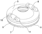
fig. 5 is a partial exploded view of a computer dust removing device according to a first embodiment of the present invention.
Description of the main symbols:
| |
1 | |
2 |
| |
3 | |
4 |
| |
5 | |
6 |
| |
7 | |
8 |
| |
9 | Vibrating |
10 |
| |
11 | |
12 |
| Limiting |
13 | |
14 |
| Inserting |
15 | |
16 |
| |
17 | |
18 |
| |
19 | Containing |
20 |
| |
21 | |
22 |
| |
23 | |
24 |
The following detailed description of the invention will be further described in conjunction with the above-identified drawings.
Detailed Description
In order to facilitate understanding of the present invention, the present invention will be described more fully hereinafter with reference to the accompanying drawings. Preferred embodiments of the present invention are shown in the drawings. The invention may, however, be embodied in many different forms and should not be construed as limited to the embodiments set forth herein. Rather, these embodiments are provided so that this disclosure will be thorough and complete.
Unless defined otherwise, all technical and scientific terms used herein have the same meaning as commonly understood by one of ordinary skill in the art to which this invention belongs. The terminology used in the description of the invention herein is for the purpose of describing particular embodiments only and is not intended to be limiting of the invention.
As used herein, the term "and/or" includes any and all combinations of one or more of the associated listed items.
When current computer removes dust after long-time the use, need dismantle the equipment of inside, then the manual work is held the brush and is cleared up the dust that adheres to on quick-witted case shell and each equipment a bit, sweeps away the dust a bit, and this process is very loaded down with trivial details, and is longer with the time spent, only relies on simple brush to clean, and the inefficiency of artifical dust removal, the in-process of dismouting can cause the damage of computer equipment simultaneously, and the dust of cleaning out is difficult for collecting.
In order to solve this problem, the utility model provides a computer dust collecting equipment please refer to fig. 1 to 5, to the utility model discloses a computer dust collecting equipment that first embodiment provided includes casing 1 to and set up negative pressure pump 3 and dust absorption pipe 4 at casing 1 both ends.
Foretell dust absorption pipe 4 and negative pressure pump 3 all communicate with dust collecting cavity 2, and 4 one ends of dust absorption pipe are equipped with suction hood 5, and the connection can be dismantled to 5 lower extremes of suction hood is equipped with collar 6, and 6 lower extremes of collar are equipped with brush hair 7, and brush hair 7 fixed connection sets up on collar 6, is equipped with vibrator 8 on the suction hood 5, and vibrator 8 is connected with 6 cooperations of collar.
Wherein, a fixing ring 9 is arranged between the dust hood 5 and the mounting ring 6, a vibrating rod 10 is fixedly connected to the fixing ring 9, a vibrating groove 11 matched with the vibrating rod 10 is formed in the dust hood 5, the vibrating rod 10 is slidably connected with the vibrating groove 11, both ends of the vibrator 8 are connected with the vibrating rod 10, the vibrator 8 is started when the device works, the vibrator 8 drives the vibrating rod 10 to slide along the vibrating groove 11, so that the fixing ring 9 vibrates, and the mounting ring 6 is driven to vibrate, so that the bristles 7 work in vibration, furthermore, a sliding rod 12 is arranged on the mounting ring 6, a limit block 13 is arranged on the sliding rod 12, a sliding groove 14 matched with the limit block 13 and the sliding rod 12 is formed in the fixing ring 9, an insertion opening 15 matched with the limit block 13 is formed in one end of the sliding groove 14, when the mounting ring 6 is replaced, the mounting ring 6 is rotated, the sliding rod 12 and the limit block 13 are pulled out in the sliding groove 14 until the limit block 13 is aligned with the insertion opening 15, the sliding rod 12 and the limit block 13 are inserted into the sliding groove 14, and the sliding groove 13 is matched with the limit block 13, and the mounting ring 6, and the sliding groove 14.
For the above-mentioned case 1, a dust collecting box 16 is arranged in the dust collecting chamber 2, the dust collecting box 16 is connected with the dust collecting chamber 2 in a sliding manner, a dust guiding pipe 17 is arranged in the dust collecting chamber 2, the dust guiding pipe 17 is communicated with the dust collecting pipe 4 and is positioned above the dust collecting box 16 and points to the dust collecting box 16, the sucked dust is introduced into the dust collecting chamber 2 from the dust guiding pipe 17 and falls into the dust collecting box 16, after cleaning, the dust collecting box 16 is directly pulled out from the dust collecting chamber 2, so that the dust in the dust collecting box 16 can be cleaned, compared with the whole equipment, a single box body is easier to operate, in addition, a first filter screen 18 is arranged in the dust collecting box 16, a second filter screen 19 is arranged at one end of the dust collecting box 16 close to the negative pressure pump 3, the density of the first filter screen 18 is lower than that of the second filter screen 19, when the dust passes through the dust collecting box 16 under the action of the negative pressure pump 3, the first filter screen 18 is in contact with the second filter screen 18, the dust collecting box 18 with the dust, the dust collecting box 16 is in contact with the second filter screen 19, and the dust, the dust filter screen 16 is prevented from being blocked, and the dust is blocked by the dust, and the dust filter screen 16.
In addition, housing cavity 20 has been seted up on casing 1, housing cavity 20 corresponds with suction hood 5 and collar 6, housing cavity 20 one end is seted up and is placed the mouth 21 with dust absorption pipe 4 corresponds, the articulated visor 22 that is equipped with on housing cavity 20, when not using, open visor 22 and expose housing cavity 20, put into housing cavity 20 with suction hood 5 and collar 6, make the crooked placing of dust absorption pipe 4 of soft material place in placing mouth 21, close visor 22, protect suction hood 5 in housing cavity 20, collar 6 and brush hair 7, avoid it impaired when placing.
Meanwhile, a lifting handle 23 is arranged at the upper end of the machine shell 1, supporting legs 24 are arranged at the lower end of the machine shell 1, when the equipment needs to be transported in preparation work or completed work, the equipment does not need to be lifted for transporting, the machine shell 1 can be driven to move only by lifting the machine shell 1 through the lifting handle 23, and when the equipment arrives at a working position, the machine shell 1 contacts with the ground through the supporting legs 24 to support the equipment to work.
For the device, when the device is used for cleaning dust in a computer, the device is driven to move through a handle 23, the device is contacted with the ground through a supporting leg 24 to support the device, the computer shell is opened, then a protective cover 22 is opened, a dust hood 5 and a mounting ring 6 are taken out from a containing cavity 20, a negative pressure pump 3 and a vibrator 8 are started, the end of the dust hood 5 is extended into the computer box to move, the dust in the computer is cleaned through bristles 7 on the mounting ring 6, at the moment, the vibrator 8 drives a vibrating rod 10 to slide along a vibrating groove 11, so that a fixing ring 9 is vibrated, the fixing ring 9 is matched with a sliding rod 12 and a limiting block 13 through a sliding groove 14 to drive the mounting ring 6 and the bristles 7 on the mounting ring 6 to vibrate, the dust on a computer and various devices are swept down by the bristles 7 in vibration, the dust is sucked into the dust suction pipe 4 along the dust suction cover 5 through the suction airflow provided by the negative pressure pump 3, enters the dust collection cavity 2 under the guide of the dust suction pipe 4 and the dust guide pipe 17, falls into the dust collection box 16, is retained in the dust collection box 16 through the matching of the first filter screen 18 and the second filter screen 19, flows to the negative pressure pump 3 through the dust collection box 16 on the airflow side, is discharged out of the devices, and is cleaned, then the dust suction cover 5 and the mounting ring 6 are contained, the dust collection box 16 is drawn out of the devices through the protection provided by the containing cavity 20, the dust in the dust collection box is cleaned and then is loaded back, and the devices are transported back through the lifting handle 23.
Finally, it should be noted that: the above-mentioned embodiments are only specific embodiments of the present invention, and are not intended to limit the technical solution of the present invention, and the protection scope of the present invention is not limited thereto, although the present invention is described in detail with reference to the foregoing embodiments, those skilled in the art should understand that: those skilled in the art can still modify or easily conceive of changes in the technical solutions described in the foregoing embodiments or make equivalent substitutions for some technical features within the technical scope of the present disclosure; such modifications, changes or substitutions do not depart from the spirit and scope of the embodiments of the present invention, and they should be construed as being included therein. Therefore, the protection scope of the present invention shall be subject to the protection scope of the claims.
Claims (5)
1. The utility model provides a computer dust collecting equipment, its characterized in that, includes the casing, set up the dust collection chamber in the casing, casing one end is equipped with the negative pressure pump, and the other end is equipped with the dust absorption pipe, the dust absorption pipe with the negative pressure pump all communicates with the dust collection chamber, dust absorption pipe one end is equipped with the suction hood, the suction hood lower extreme can be dismantled and connect and be equipped with the collar, the collar lower extreme is equipped with the brush hair, brush hair fixed connection sets up on the collar, be equipped with the vibrator on the suction hood, the vibrator with the collar cooperation is connected, the suction hood with be equipped with solid fixed ring between the collar, gu fixed ring goes up fixed connection and is equipped with the vibrating arm, set up on the suction hood with vibrating arm complex vibration groove, the vibrating arm with vibration groove sliding connection, the vibrator both ends all with the vibrating arm is connected, be equipped with the slide bar on the collar, be equipped with the stopper on the slide bar, gu fixed ring set up with stopper with slide bar complex sliding groove, slide groove one end be equipped with stopper complex inserted hole.
2. The computer dust removing device of claim 1, wherein a dust collecting box is arranged in the dust collecting chamber, the dust collecting box is slidably connected with the dust collecting chamber, a dust guide pipe is arranged in the dust collecting chamber, the dust guide pipe is communicated with the dust suction pipe, is positioned above the dust collecting box, and points to the dust collecting box.
3. The computer dust removing device of claim 2, wherein a first filter screen is arranged in the dust collecting box, a second filter screen is arranged at one end of the dust collecting box close to the negative pressure pump, and the density of the first filter screen is lower than that of the second filter screen.
4. The computer dust removing device of claim 1, wherein the housing has a receiving cavity, one end of the receiving cavity has a placing opening corresponding to the dust suction pipe, and the receiving cavity is hinged to a protective cover.
5. The computer dust removing device of claim 1, wherein a handle is provided at an upper end of the housing, and a support leg is provided at a lower end of the housing.
Priority Applications (1)
| Application Number | Priority Date | Filing Date | Title |
|---|---|---|---|
| CN202222773370.1U CN217804043U (en) | 2022-10-21 | 2022-10-21 | Computer dust collecting equipment |
Applications Claiming Priority (1)
| Application Number | Priority Date | Filing Date | Title |
|---|---|---|---|
| CN202222773370.1U CN217804043U (en) | 2022-10-21 | 2022-10-21 | Computer dust collecting equipment |
Publications (1)
| Publication Number | Publication Date |
|---|---|
| CN217804043U true CN217804043U (en) | 2022-11-15 |
Family
ID=83976943
Family Applications (1)
| Application Number | Title | Priority Date | Filing Date |
|---|---|---|---|
| CN202222773370.1U Active CN217804043U (en) | 2022-10-21 | 2022-10-21 | Computer dust collecting equipment |
Country Status (1)
| Country | Link |
|---|---|
| CN (1) | CN217804043U (en) |
Cited By (1)
| Publication number | Priority date | Publication date | Assignee | Title |
|---|---|---|---|---|
| CN116422654A (en) * | 2023-06-13 | 2023-07-14 | 国网山东省电力公司诸城市供电公司 | Power distribution cabinet cleaning device |
-
2022
- 2022-10-21 CN CN202222773370.1U patent/CN217804043U/en active Active
Cited By (2)
| Publication number | Priority date | Publication date | Assignee | Title |
|---|---|---|---|---|
| CN116422654A (en) * | 2023-06-13 | 2023-07-14 | 国网山东省电力公司诸城市供电公司 | Power distribution cabinet cleaning device |
| CN116422654B (en) * | 2023-06-13 | 2023-08-11 | 国网山东省电力公司诸城市供电公司 | Power distribution cabinet cleaning device |
Similar Documents
| Publication | Publication Date | Title |
|---|---|---|
| CN217804043U (en) | Computer dust collecting equipment | |
| CN210080316U (en) | Computer hardware ash removal device | |
| CN205263714U (en) | Dustproof computer screen | |
| CN209424109U (en) | Processing unit is cleaned with dust inside a kind of high voltage electric equipment | |
| CN109894271A (en) | A kind of anti-dust remover for computer automation system | |
| CN108720722A (en) | A kind of easy to clean Efficient dust collector | |
| CN211707592U (en) | Electronic product dust collector | |
| CN109700374B (en) | Automatic cleaning anti-blocking dust collector | |
| CN209932599U (en) | Dust absorption mopping all-in-one machine | |
| CN108838175A (en) | A kind of blowing pipeline silencing means | |
| CN212371869U (en) | Mechanical surface grinding device | |
| CN211513814U (en) | Filter screen belt cleaning device of central vacuum cleaner | |
| CN210814354U (en) | Vibration type bag-type dust collector | |
| CN218419642U (en) | Cleaning equipment for intelligent equipment software and hardware maintenance | |
| CN220352463U (en) | Clean scrubbing equipment | |
| CN207627231U (en) | Window slot dust accumulation cleaner and full-automatic window slot cleaner | |
| CN210546760U (en) | Electric automation equipment maintenance dust collector | |
| CN217595388U (en) | Electrified dust collector of desktop computer machine case | |
| CN218304698U (en) | Dust extraction's host computer and use its cleaning equipment with heat dissipation function | |
| CN219165170U (en) | Guard shield with clearance structure | |
| CN213690493U (en) | Dustproof device for computer | |
| CN215191290U (en) | Inhale and drag all-in-one | |
| CN215769591U (en) | Computer machine case with dust removal purification performance | |
| CN217314899U (en) | Computer case with bottom dust deposition intelligent scraping structure | |
| CN208374866U (en) | A kind of smart car commutator removes duct mechanism |
Legal Events
| Date | Code | Title | Description |
|---|---|---|---|
| GR01 | Patent grant | ||
| GR01 | Patent grant |