CN217802442U - Fly ash solidification device for waste incineration power generation - Google Patents
Fly ash solidification device for waste incineration power generation Download PDFInfo
- Publication number
- CN217802442U CN217802442U CN202221318809.5U CN202221318809U CN217802442U CN 217802442 U CN217802442 U CN 217802442U CN 202221318809 U CN202221318809 U CN 202221318809U CN 217802442 U CN217802442 U CN 217802442U
- Authority
- CN
- China
- Prior art keywords
- mixing
- stirring
- shaft
- stirring tank
- tank
- Prior art date
- Legal status (The legal status is an assumption and is not a legal conclusion. Google has not performed a legal analysis and makes no representation as to the accuracy of the status listed.)
- Active
Links
Images

Landscapes
- Processing Of Solid Wastes (AREA)
Abstract
The utility model relates to a fly ash solidification device for waste incineration power generation.A mixing and stirring tank is provided with an opening at the upper end, a blanking pipe at the lower end, a spray pipe inside, a spray head inside the spray pipe, and a flow controller, a pressure pump and a water storage tank outside the spray pipe; the top cover is positioned above the opening end of the mixing and stirring tank, a stirring shaft is rotatably penetrated in the center of the top cover, the stirring shaft is concentrically connected with a driving motor, the lower end of the stirring shaft is positioned in the mixing and stirring tank, and a plurality of stirring blades are arranged on two sides of the stirring shaft in a staggered manner; the material scraping devices are respectively arranged on two sides of the lower end of the stirring shaft, one side of the scraping plate is in contact with the inner wall of the mixing and stirring tank, the other side of the scraping plate is in limit connection with the stirring shaft through an adjusting part, the adjusting part comprises an outer sleeve and an inner rod which is arranged in the outer sleeve in a sliding manner, an electromagnet is fixedly arranged inside the connecting end of the outer sleeve and the stirring shaft, the inner rod is an ironwork, and a spring is arranged between the inner rod and the electromagnet; the utility model has the advantages of stable in structure is reasonable and excellent in use effect.
Description
Technical Field
The utility model belongs to the waste incineration power generation field, concretely relates to flying dust solidification equipment of waste incineration power generation.
Background
At present, the waste incineration technology becomes a main means for treating domestic waste in major and middle cities in China, and waste incineration fly ash is fine particulate matters finally collected by a flue gas purification device after inorganic components are subjected to violent and complex thermochemical reaction, diffusion, crushing, condensation and other physical actions in the process of domestic waste incineration; in the technical policy for preventing and treating hazardous waste pollution issued by the general office for environmental protection in 2001 of China, the fly ash from incineration of household garbage is defined as hazardous waste: the fly ash generated by burning the household garbage must be collected separately, the fly ash generated by burning the household garbage must be transported after necessary solidification and stabilization treatment in a production place, the fly ash generated by burning the household garbage must be safely buried, and the like; however, when the fly ash solidifying device of the existing garbage incineration unit is used, the contact between the fly ash and the cementing material is insufficient due to poor integral stirring effect, so that the fly ash after subsequent solidification is stable is loose and messy, and the transportation and the landfill operation of the fly ash are affected; therefore, in order to solve the above problems, it is necessary to develop a fly ash solidification device for waste incineration power generation, which has a stable and reasonable structure and good use effect.
SUMMERY OF THE UTILITY MODEL
The utility model aims at overcoming the defects of the prior art and providing a fly ash solidification device for waste incineration power generation, which has stable and reasonable structure and good use effect.
The purpose of the utility model is realized like this: a fly ash solidification device for waste incineration power generation comprises a mixing and stirring tank, a top cover, a conduit and a scraping device, wherein the mixing and stirring tank is integrally cylindrical, the upper end of the mixing and stirring tank is provided with an opening, the lower end of the mixing and stirring tank is conical, a discharging pipe is arranged in the center of the mixing and stirring tank, a control valve is arranged outside the discharging pipe, a spray pipe is fixedly arranged at the upper end of the inner surface of the mixing and stirring tank in a spiral shape, a plurality of spray heads are uniformly and fixedly arranged on the inner side of the spray pipe, one end of the conduit is communicated with the spray pipe, the other end of the conduit is positioned outside the mixing and stirring tank, and a pressure pump and a water storage tank are externally connected through a flow controller; the top cover is detachably arranged above the opening end of the mixing and stirring tank, a stirring shaft is rotatably penetrated in the center of the top cover, a material injection pipe a and a material injection pipe b are respectively arranged on two sides of the upper surface of the top cover, the upper end of the stirring shaft is positioned above the top cover and is concentrically connected with a driving motor, the lower end of the stirring shaft is positioned in the mixing and stirring tank, and a plurality of stirring blades are arranged on two sides of the stirring shaft in a staggered manner; the scraper device has two sets ofly, and the symmetry sets up in the both sides of (mixing) shaft lower extreme respectively, and it includes scraper blade and regulating part, the scraper blade with the (mixing) shaft is the parallel form, its one side and the inner wall contact of mixing agitator tank, and the middle part of opposite side is passed through regulating part and (mixing) shaft spacing connection, the regulating part includes outer tube and interior pole, the outer tube is connected with the perpendicular fixed of (mixing) shaft, and the fixed electro-magnet that is provided with in inside of outer tube and (mixing) shaft link, interior pole is ironwork, and the inside of outer tube is worn to locate in its one end slides, other end and scraper blade fixed connection, and interior pole is located between the one end of the inside of outer tube and the electro-magnet fixed spring that is provided with.
The inside lower extreme of mixing agitator tank is provided with the reinforcement, the reinforcement includes the dead lever and the spacing lantern ring, the outside of (mixing) shaft lower extreme is established to the spacing lantern ring rotation cover, the dead lever has two, and the symmetry sets up respectively in the both sides of the spacing lantern ring, and the outer fixed surface of dead lever one end and the spacing lantern ring is connected, the inner wall fixed connection of the other end and mixing agitator tank.
And a rubber layer is fixedly arranged at one end of the scraper plate, which is contacted with the inner wall of the mixing and stirring tank.
The middle part of the upper surface of the top cover is fixedly provided with a motor support, and the driving motor is positioned above the motor support.
The outer sleeve and the inner rod are both square structures.
The utility model has the advantages that: the utility model is provided with the material injection pipe a and the material injection pipe b, so that fly ash and cement can be respectively added into the mixing and stirring tank through the material injection pipe a and the material injection pipe b; by arranging the spray pipe, the spray header, the guide pipe and the flow controller, the water for mixing and stirring can be injected into the spray pipe through the guide pipe under the pressurization effect of the external pressurization pump and is uniformly sprayed out from the spray header inside the mixing and stirring tank, so that the uniformity of the water distribution inside the mixing and stirring tank is improved, and meanwhile, the flow rate and the total amount of the added water can be controlled by utilizing the flow controller; by arranging the scraper blade, the adjusting piece, the outer sleeve, the inner rod, the electromagnet and the spring, when the top cover is installed, the electrifying circuit of the electromagnet is opened, the magnetic attraction effect on the iron inner rod after the electromagnet is electrified can be used for driving the inner rod and the scraper blade to move inwards, and the spring is contracted, so that the problem that the scraping device cannot be installed along with the top cover due to the existence of a spray pipe on the upper end of the inner surface of the mixing stirring tank is avoided; generally, the utility model has the advantages of stable in structure is reasonable and excellent in use effect.
Drawings
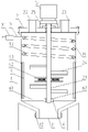
Fig. 1 is a sectional view of a front view of the present invention.
Fig. 2 is a sectional view of a front view of an adjusting member according to the present invention.
In the figure: 1. the device comprises a mixing and stirring tank 11, a blanking pipe 12, a control valve 13, a spray pipe 14, a spray header 2, a top cover 21, a stirring shaft 22, a material injection pipe a 23, a material injection pipe b 24, a stirring blade 25, a motor support 3, a guide pipe 31, a flow controller 4, a scraping device 41, a scraping plate 42, an adjusting part 421, an outer sleeve 422, an inner rod 423, an electromagnet 424, a spring 5, a driving motor 6, a reinforcing part 61, a fixed rod 62 and a limiting sleeve ring.
Detailed Description
The present invention will be further described with reference to the accompanying drawings.
The embodiment is as follows: as shown in fig. 1 and 2, a fly ash solidification device for waste incineration power generation comprises a mixing and stirring tank 1, a top cover 2, a conduit 3 and a scraping device 4, wherein the mixing and stirring tank 1 is integrally cylindrical, the upper end of the mixing and stirring tank is provided with an opening, the lower end of the mixing and stirring tank is conical, a discharging pipe 11 is arranged in the center of the mixing and stirring tank, a control valve 12 is arranged outside the discharging pipe 11, a spray pipe 13 is fixedly arranged at the upper end of the inner surface of the mixing and stirring tank 1 in a spiral shape, a plurality of spray heads 14 are uniformly and fixedly arranged inside the spray pipe 13, one end of the conduit 3 is communicated with the spray pipe 13, the other end of the conduit is positioned outside the mixing and stirring tank 1, and is externally connected with a pressure pump and a water storage tank through a flow controller 31; the top cover 2 is detachably arranged above the opening end of the mixing and stirring tank 1, a stirring shaft 21 is rotatably penetrated in the center of the top cover, a material injection pipe a22 and a material injection pipe b23 are respectively arranged on two sides of the upper surface of the top cover, the upper end of the stirring shaft 21 is positioned above the top cover 2 and is concentrically connected with a driving motor 5, the lower end of the stirring shaft is positioned in the mixing and stirring tank 1, and a plurality of stirring blades 24 are arranged on two sides in a staggered mode; scraper 4 has two sets ofly, and the symmetry sets up in the both sides of (mixing) shaft 21 lower extreme respectively, and it includes scraper blade 41 and regulating part 42, scraper blade 41 with (mixing) shaft 21 is parallel form, its one side and the inner wall contact of mixing agitator tank 1, and the middle part of opposite side is passed through regulating part 42 and is connected with (mixing) shaft 21 is spacing, regulating part 42 includes outer tube 421 and interior pole 422, outer tube 421 and the perpendicular fixed connection of (mixing) shaft 21, and the inside fixed electro-magnet 423 that is provided with of outer tube 421 and (mixing) shaft 21 link, interior pole 422 is ironwork, and the inside of outer tube 421 is worn to locate in its one end slides, the other end and scraper blade 41 fixed connection, and interior pole 422 is located and is fixed spring 424 that is provided with between the one end of the inside of outer tube 421 and the electro-magnet 423.
The lower end of the interior of the mixing and stirring tank 1 is provided with a reinforcing member 6, the reinforcing member 6 comprises a fixing rod 61 and a limiting sleeve ring 62, the limiting sleeve ring 62 is rotatably sleeved outside the lower end of the stirring shaft 21, two fixing rods 61 are respectively and symmetrically arranged on two sides of the limiting sleeve ring 62, one end of each fixing rod 61 is fixedly connected with the outer surface of the limiting sleeve ring 62, the other end of each fixing rod 61 is fixedly connected with the inner wall of the mixing and stirring tank 1, and the fixing rod 61 and the limiting sleeve ring 62 are utilized to improve the stability of the whole stirring shaft 21 in use while the rotation of the stirring shaft 21 is not influenced; a rubber layer is fixedly arranged at one end of the scraper 41, which is in contact with the inner wall of the mixing and stirring tank 1, and can play a certain role in buffering and protection, a motor support 25 is fixedly arranged in the middle of the upper surface of the top cover 2, the driving motor 5 is positioned above the motor support 25, and the driving motor 5 can be conveniently supported and placed by the motor support 25; the outer sleeve 421 and the inner rod 422 are both square structures, and the relative rotation between the outer sleeve 421 and the inner rod 422 can be avoided by utilizing the square structures.
The utility model discloses when installing top cap 2 before the use, open the circular telegram circuit of electro-magnet 423 earlier, utilize the magnetic attraction effect of pole 422 in the iron-on back to the circular telegram of electro-magnet 423, pole 422 and scraper blade 41 move to the inboard in can driving, and make the shrink of spring 424, thereby avoid because of the existence of 1 internal surface upper end shower 13 of mixing agitator tank, and because of blockking to cause scraping device 4 can't carry out the problem of installing along with top cap 2, then, treat the top cap 2 lower surface and mixing agitator tank 1's upper end after-contact, utilize spacing screw can realize top cap 2 and mixing agitator tank 1 between spacing being connected.
When the top cover 2 of the utility model is used after being installed, firstly, the power-on circuit of the electromagnet 423 is cut off, so that the electromagnet 423 loses the magnetic attraction to the iron inner rod 422, at the moment, by utilizing the elastic thrust action of the spring 424, the inner rod 422 and the scraping plate 41 are driven to move outwards, so that the scraping plate 41 is in close contact with the inner wall of the mixing and stirring tank 1, then, fly ash and cement are added into the interior of the mixing and stirring tank 1 through a feed pipe a22 and a feed pipe b23, respectively, and at the same time, a pressurizing pump is turned on, under the pressurization action of an external pressurization pump, the water for mixing and stirring is injected into the spray pipe 13 through the conduit 3, and is uniformly sprayed out from the spray header 14 in the mixing and stirring tank 1, finally, after the fly ash, the cement and the water for mixing and stirring are added, the driving motor 5 is started, the rotation of the driving motor 5 is utilized to drive the stirring shaft 21 to rotate, and then the stirring blade 24 is driven to rotate by the rotation of the stirring shaft 21, so that the fly ash, the cement and the water in the mixing and stirring tank 1 are mixed and stirred, and meanwhile, the limit connection between the scraping device 4 and the stirring shaft 21 is utilized, when the stirring shaft 21 rotates, the scraping device 4 can be driven to rotate together, so that the scraping plate 41 is utilized to scrape the materials adhered to the inner wall of the mixing and stirring tank 1, can improve the mixing and stirring effect when in use, can also reduce the cleaning difficulty of the subsequent mixing and stirring tank 1, and after the operation is finished, after the fly ash, the cement and the water are fully mixed, the control valve 12 is opened, the mixture is discharged from the discharging pipe 11, at the moment, the characteristics of the cementing material cement are utilized, the integral solidification of the mixture can be realized after the mixture is kept still for a period of time, namely the solidification operation of the fly ash is completed; generally, the utility model has the advantages of stable in structure is reasonable and excellent in use effect.
Claims (5)
1. The utility model provides a fly ash solidification equipment of msw incineration power generation, includes mixing tank, top cap, pipe and scraper, its characterized in that: the mixing and stirring tank is integrally cylindrical, the upper end of the mixing and stirring tank is provided with an opening, the lower end of the mixing and stirring tank is conical, a discharging pipe is arranged in the center of the mixing and stirring tank, a control valve is arranged outside the discharging pipe, a spraying pipe is fixedly arranged at the upper end of the inner surface of the mixing and stirring tank in a spiral shape, a plurality of spraying heads are uniformly and fixedly arranged inside the spraying pipe, one end of a guide pipe is communicated with the spraying pipe, the other end of the guide pipe is positioned outside the mixing and stirring tank, and a pressure pump and a water storage tank are externally connected through a flow controller; the top cover is detachably arranged above the opening end of the mixing and stirring tank, a stirring shaft is rotatably penetrated in the center of the top cover, a material injection pipe a and a material injection pipe b are respectively arranged on two sides of the upper surface of the top cover, the upper end of the stirring shaft is positioned above the top cover and is concentrically connected with a driving motor, the lower end of the stirring shaft is positioned in the mixing and stirring tank, and a plurality of stirring blades are arranged on two sides of the stirring shaft in a staggered manner; scraper device has two sets ofly, and the symmetry sets up in the both sides of (mixing) shaft lower extreme respectively, and it includes scraper blade and regulating part, the scraper blade with the (mixing) shaft is parallel form, its one side and the inner wall contact of mixing agitator tank, and the middle part of opposite side is passed through regulating part and (mixing) shaft limit connection, the regulating part includes outer tube and interior pole, outer tube and the perpendicular fixed connection of (mixing) shaft, and the fixed electro-magnet that is provided with in inside of outer tube and (mixing) shaft link, interior pole is ironwork, and the inside of outer tube is worn to locate in its one end slip, the other end and scraper blade fixed connection, and the interior pole is located to fix between the one end of the inside of outer tube and the electro-magnet and is provided with the spring.
2. The fly ash solidification device for waste incineration power generation as claimed in claim 1, wherein: the inside lower extreme of mixing agitator tank is provided with the reinforcement, the reinforcement includes the dead lever and the spacing lantern ring, the outside of (mixing) shaft lower extreme is established to the spacing lantern ring rotation cover, the dead lever has two, and the symmetry sets up in the both sides of the spacing lantern ring respectively, and the outer fixed surface of dead lever one end and the spacing lantern ring is connected, the inner wall fixed connection of the other end and mixing agitator tank.
3. The fly ash solidification device for waste incineration power generation as claimed in claim 1, wherein: and a rubber layer is fixedly arranged at one end of the scraper blade, which is in contact with the inner wall of the mixing and stirring tank.
4. The fly ash solidification device for waste incineration power generation as claimed in claim 1, wherein: the middle part of the upper surface of the top cover is fixedly provided with a motor support, and the driving motor is positioned above the motor support.
5. The fly ash solidification device for waste incineration power generation as claimed in claim 1, wherein: the outer sleeve and the inner rod are both square structures.
Priority Applications (1)
| Application Number | Priority Date | Filing Date | Title |
|---|---|---|---|
| CN202221318809.5U CN217802442U (en) | 2022-05-30 | 2022-05-30 | Fly ash solidification device for waste incineration power generation |
Applications Claiming Priority (1)
| Application Number | Priority Date | Filing Date | Title |
|---|---|---|---|
| CN202221318809.5U CN217802442U (en) | 2022-05-30 | 2022-05-30 | Fly ash solidification device for waste incineration power generation |
Publications (1)
| Publication Number | Publication Date |
|---|---|
| CN217802442U true CN217802442U (en) | 2022-11-15 |
Family
ID=83988406
Family Applications (1)
| Application Number | Title | Priority Date | Filing Date |
|---|---|---|---|
| CN202221318809.5U Active CN217802442U (en) | 2022-05-30 | 2022-05-30 | Fly ash solidification device for waste incineration power generation |
Country Status (1)
| Country | Link |
|---|---|
| CN (1) | CN217802442U (en) |
Cited By (1)
| Publication number | Priority date | Publication date | Assignee | Title |
|---|---|---|---|---|
| CN116551855A (en) * | 2023-07-12 | 2023-08-08 | 泗洪高能环境生物质能有限公司 | Waste incineration power generation fly ash solidification device |
-
2022
- 2022-05-30 CN CN202221318809.5U patent/CN217802442U/en active Active
Cited By (2)
| Publication number | Priority date | Publication date | Assignee | Title |
|---|---|---|---|---|
| CN116551855A (en) * | 2023-07-12 | 2023-08-08 | 泗洪高能环境生物质能有限公司 | Waste incineration power generation fly ash solidification device |
| CN116551855B (en) * | 2023-07-12 | 2023-10-20 | 泗洪高能环境生物质能有限公司 | Waste incineration power generation fly ash solidification device |
Similar Documents
| Publication | Publication Date | Title |
|---|---|---|
| CN217802442U (en) | Fly ash solidification device for waste incineration power generation | |
| CN107379264A (en) | A kind of two tank mixers easy to remove | |
| CN205600978U (en) | Concrete mixing equipment for building engineering | |
| CN103612330B (en) | A kind of concrete mixer of automatic water jetting | |
| CN205340652U (en) | Integration agitator | |
| CN208003804U (en) | A kind of mixed medicine structure of the dosing of integrated sewage treating apparatus | |
| CN116036958A (en) | Mixing arrangement that can evenly compounding fast for construction | |
| CN204221976U (en) | The even feed proportioning system of air entrained concrete | |
| CN215038907U (en) | Fly ash foam concrete apparatus for producing | |
| CN215161934U (en) | Sewage treatment plant based on microorganism natural degradation | |
| CN216273372U (en) | High-efficiency low-consumption medical sewage intelligent treatment system | |
| CN210651301U (en) | Waste brick particle stirring and mixing device | |
| CN210278976U (en) | Even device of raw materials for civil engineering | |
| CN109927169A (en) | A kind of civil engineering concrete biaxial blender | |
| CN210589892U (en) | Mortar stirring equipment | |
| CN207872339U (en) | Coal ash for manufacturing pulp grinder | |
| CN205704681U (en) | Civil construction material flows is mixed with processing means | |
| CN108213049B (en) | Sulfonates acid sludge treatment equipment | |
| CN219190706U (en) | Energy-saving construction device for building | |
| CN221359623U (en) | Inorganic clay mineral activation and drying device | |
| CN208032341U (en) | A kind of starch fluid blender | |
| CN213611241U (en) | Ceramsite sand granulating device with atomization auxiliary structure | |
| CN215150391U (en) | Concrete mixing device is used in road bridge construction | |
| CN205766855U (en) | A kind of building materials material stirring control system | |
| CN221436772U (en) | Concrete stirring device |
Legal Events
| Date | Code | Title | Description |
|---|---|---|---|
| GR01 | Patent grant | ||
| GR01 | Patent grant |