CN217799366U - Vertical saw with saw frame walking device - Google Patents
Vertical saw with saw frame walking device Download PDFInfo
- Publication number
- CN217799366U CN217799366U CN202222093982.6U CN202222093982U CN217799366U CN 217799366 U CN217799366 U CN 217799366U CN 202222093982 U CN202222093982 U CN 202222093982U CN 217799366 U CN217799366 U CN 217799366U
- Authority
- CN
- China
- Prior art keywords
- rack
- saw
- gear
- frame
- drive gear
- Prior art date
- Legal status (The legal status is an assumption and is not a legal conclusion. Google has not performed a legal analysis and makes no representation as to the accuracy of the status listed.)
- Active
Links
Images


Abstract
The utility model provides a vertical saw with sash running gear, including workstation and frame, the frame includes frame, lower frame and base, and parallel arrangement slide rail and rack on the base, and set up the mount on the lower frame lateral wall, and set up in the driving motor of lower frame one end, and the drive gear who links to each other with the driving motor transmission, and the drive gear who meshes with drive gear mutually, and be used for installing drive gear and drive gear's mounting bracket, and shelter from the protection casing on the mounting bracket. The vertical saw is driven to integrally move by the driving gear matched with the rack, so that the vertical saw cannot slip when moving due to the existence of the rack, uniform movement is guaranteed, and cutting quality is guaranteed; the two slide rails are arranged, and the slide block arranged at the bottom of the fixed frame is matched with the slide rails to prevent the slide rails from deviating in the moving process; the both ends and the side of slide rail all are provided with the limiting plate, prevent that the condition of derailing from appearing at the removal in-process of standing the saw.
Description
Technical Field
The utility model relates to a vertical saw with a saw frame walking device.
Background
The metal band sawing machine is a sawing device which uses a metal saw blade as a cutting tool and is used for cutting various materials, and is mainly used for cutting nonferrous metals, non-metal materials and various sectional materials, before the plates with larger size are processed into corresponding workpieces, the plates are required to be cut into small blank materials, but when the existing metal plates or non-metal materials with larger size are cut, the oil cylinder is adopted for propelling or the speed reducer is adopted for driving the trundle to propel the metal plates or non-metal materials to carry out sawing processing, therefore, the operation difficulty is high, the precision is poor, the sawing efficiency is low, the S line is easy to walk in the sawing process, the materials and manpower are wasted, the weight of the plates is large, the actual control of an operator is very inconvenient, meanwhile, the feeding speed of the operator is influenced by subjective factors, and the control and the adjustment are not easy.
SUMMERY OF THE UTILITY MODEL
The utility model discloses solve the technical problem that prior art exists to a simple structure only needs to aim at the automatic saw cutting of panel size according to the infrared ray, labour saving and time saving cuts efficiency, the high upright saw that has the sash running gear of cutting quality.
The purpose of the utility model can be realized by the following technical proposal:
the utility model provides a found saw with sash running gear, includes workstation and frame, the frame includes frame, lower frame and base, and parallel arrangement slide rail and rack on the base, and set up the mount on the lower frame lateral wall, and set up in the driving motor of lower frame one end, and the drive gear who links to each other with the driving motor transmission, and the drive gear who meshes mutually with drive gear, and be used for installing drive gear and drive gear's mounting bracket, and shelter from the protection casing on the mounting bracket, and set up the switch board in last frame, drive gear and rack cooperate, the mount bottom is provided with the slider, the slider suit is on the slide rail.
Preferably, the slide rail is two, the rack sets up in the middle of two slide rails, the length of rack is less than the length of slide rail, the both ends and the side of slide rail all are provided with the limiting plate.
Preferably, the diameter of the driving gear is larger than that of the transmission gear, the lower end of the driving gear is meshed with the rack, the upper end of the driving gear is meshed with the transmission gear, and the rotating directions of the driving gear and the transmission gear are opposite.
Preferably, the driving motor, the driving gear and the transmission gear are all arranged in the protective cover.
Preferably, grooves are formed in two sides of the sliding rail, and protruding blocks are arranged on two sides of the inner side of the contact surface of the sliding block and the sliding rail.
Preferably, the lower frame is arranged on the base, the upper frame is arranged on the lower frame, and the control cabinet is connected with the driving motor.
The utility model discloses have the beneficial effect of hacksaw of sash running gear: the vertical saw with the saw frame walking device is provided with the driving gear which is matched with the rack to drive the vertical saw to move integrally, so that the vertical saw cannot slip when moving due to the existence of the rack, the uniform movement is ensured, and the cutting quality is ensured; the two slide rails are arranged, and the slide block arranged at the bottom of the fixed frame is matched with the slide rails to prevent the slide rails from deviating in the moving process; the both ends and the side of slide rail all are provided with the limiting plate, prevent that the condition of derailing from appearing at the removal in-process of standing the saw.
Drawings
In order to more clearly illustrate the embodiments of the present invention or the technical solutions in the prior art, the drawings used in the description of the embodiments or the prior art will be briefly described below, it is obvious that the drawings in the following description are only some embodiments of the present invention, and for those skilled in the art, other drawings can be obtained according to these drawings without creative efforts.
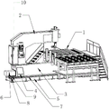
FIG. 1 is a schematic structural view of a vertical saw with a saw frame walking device of the utility model;
FIG. 2 is a schematic structural view of the vertical saw with a saw frame walking device for dismantling the protective cover of the utility model;
FIG. 3 is a schematic view of the structure of the fixing frame of the vertical saw with the saw frame walking device of the utility model;
in the figure: 1. a work table; 2. an upper frame; 3. a lower frame; 4. a fixed mount; 5. a base; 6. a protective cover; 7. a slide rail; 8. a rack; 9. a drive gear; 10. a control cabinet; 11. a transmission gear; 12. a drive motor; 13. a mounting frame; 401. a slide block.
Detailed Description
The following are specific embodiments of the present invention and the accompanying drawings are used to further describe the technical solution of the present invention, but the present invention is not limited to these embodiments.
As shown in fig. 1 to fig. 3, the utility model adopts the following technical scheme: the utility model provides a vertical saw with sash running gear, includes workstation 1 and frame, the frame includes frame 2, lower frame 3 and base 5, and parallel arrangement slide rail 7 and rack 8 on base 5, and set up mount 4 on 3 lateral walls of lower frame, and set up in the driving motor 12 of 4 one ends of lower frame, and the drive gear 11 that links to each other with driving motor 12 transmission, and the drive gear 9 who meshes with drive gear 11 mutually, and be used for installing drive gear 11 and drive gear 9's mounting bracket 13, and shelter from protection casing 6 on mounting bracket 13, and set up switch board 10 on last frame 2, drive gear 9 cooperatees with rack 8, mount 4 bottoms are provided with slider 401, slider 401 suit is on slide rail 7.
The slide rail 7 is two, rack 8 sets up in the middle of two slide rails 7, rack 8's length is less than slide rail 7's length, slide rail 7's both ends and side all are provided with limiting plate (not shown).
The diameter of the driving gear 9 is larger than that of the transmission gear 11, the lower end of the driving gear 9 is meshed with the rack 8, the upper end of the driving gear 9 is meshed with the transmission gear 11, and the rotating directions of the driving gear 9 and the transmission gear 11 are opposite.
The driving motor 12, the driving gear 9 and the transmission gear 11 are all arranged in the protective cover 6.
Grooves are formed in two sides of the sliding rail 7, and protruding blocks are arranged on two sides of the contact surface of the sliding block 401 and the sliding rail 7.
The lower rack 3 is arranged on the base 5, the upper rack 2 is arranged on the lower rack 3, and the control cabinet 10 is connected with the driving motor 12.
Opening of switch board 10 control driving motor 12 stops and the direction of rotation, driving motor 12 drives drive gear 11 and rotates, drive gear 11 drives the drive gear 9 rotation of meshing with it, drive gear 9's rotation and rack 8 are mutually supported down, make vertical saw moving as a whole, rack 8 both sides parallel arrangement's 7 length of slide rail are greater than the length of rack 8 itself, the moving range of vertical saw has been guaranteed, the both ends and the side of slide rail 7 all are provided with the limiting plate, can prevent again that vertical saw from the condition that the derailment appears at the removal in-process, slider 401 and the cooperation of slide rail 7 that the 4 bottoms of mount set up, prevent to take place the skew at the removal in-process.
The utility model discloses have the beneficial effect of hacksaw of sash running gear: the vertical saw with the saw frame walking device is provided with the driving gear which is matched with the rack to drive the vertical saw to move integrally, so that the vertical saw cannot slip when moving due to the existence of the rack, the uniform movement is ensured, and the cutting quality is ensured; the two slide rails are arranged, and the slide block arranged at the bottom of the fixed frame is matched with the slide rails to prevent the slide rails from deviating in the moving process; the both ends and the side of slide rail all are provided with the limiting plate, prevent that the condition of derailing from appearing at the removal in-process of standing the saw.
It is to be understood that in the claims, the specification of the present invention, all "including … …" are to be understood in an open meaning, i.e., in a meaning equivalent to "including at least … …", and not in a closed meaning, i.e., in a meaning not to be understood as "including only … …".
The specific embodiments described herein are merely illustrative of the spirit of the invention. Various modifications, additions and substitutions for the specific embodiments described herein may be made by those skilled in the art without departing from the spirit of the invention or exceeding the scope of the invention as defined in the accompanying claims.
Claims (6)
1. The utility model provides a found saw with sash running gear which characterized in that: the automatic control device comprises a workbench and a rack, wherein the rack comprises an upper rack, a lower rack and a base, a sliding rail and a rack which are arranged on the base in parallel, a fixing frame arranged on the side wall of the lower rack, a driving motor arranged at one end of the lower rack, a transmission gear connected with the driving motor in a transmission manner, a driving gear meshed with the transmission gear, a mounting frame used for mounting the transmission gear and the driving gear, a protective cover sheltered on the mounting frame, and a control cabinet arranged on the upper rack, the driving gear is matched with the rack, a sliding block is arranged at the bottom of the fixing frame, and the sliding block is sleeved on the sliding rail.
2. The standing saw with the saw frame walking device as claimed in claim 1, wherein: the slide rail is two, the rack sets up in the middle of two slide rails, the length of rack is less than the length of slide rail, the both ends and the side of slide rail all are provided with the limiting plate.
3. The standing saw with the saw frame walking device as claimed in claim 1, wherein: the diameter of the driving gear is larger than that of the transmission gear, the lower end of the driving gear is meshed with the rack, the upper end of the driving gear is meshed with the transmission gear, and the rotating directions of the driving gear and the transmission gear are opposite.
4. The standing saw with the saw frame walking device as claimed in claim 1, wherein: the driving motor, the driving gear and the transmission gear are all arranged in the protective cover.
5. The vertical saw with the saw frame walking device as claimed in claim 1, wherein: grooves are formed in two sides of the sliding rail, and protruding blocks are arranged on two sides of the inner side of the contact surface of the sliding block and the sliding rail.
6. The standing saw with the saw frame walking device as claimed in claim 1, wherein: the lower rack is arranged on the base, the upper rack is arranged on the lower rack, and the control cabinet is connected with the driving motor.
Priority Applications (1)
| Application Number | Priority Date | Filing Date | Title |
|---|---|---|---|
| CN202222093982.6U CN217799366U (en) | 2022-08-09 | 2022-08-09 | Vertical saw with saw frame walking device |
Applications Claiming Priority (1)
| Application Number | Priority Date | Filing Date | Title |
|---|---|---|---|
| CN202222093982.6U CN217799366U (en) | 2022-08-09 | 2022-08-09 | Vertical saw with saw frame walking device |
Publications (1)
| Publication Number | Publication Date |
|---|---|
| CN217799366U true CN217799366U (en) | 2022-11-15 |
Family
ID=83974163
Family Applications (1)
| Application Number | Title | Priority Date | Filing Date |
|---|---|---|---|
| CN202222093982.6U Active CN217799366U (en) | 2022-08-09 | 2022-08-09 | Vertical saw with saw frame walking device |
Country Status (1)
| Country | Link |
|---|---|
| CN (1) | CN217799366U (en) |
-
2022
- 2022-08-09 CN CN202222093982.6U patent/CN217799366U/en active Active
Similar Documents
| Publication | Publication Date | Title |
|---|---|---|
| CN210025547U (en) | Circuit board punching device | |
| CN215145258U (en) | Aluminum plate cutting equipment for machining | |
| CN209920264U (en) | Track rotary cutting machine for cutting concrete | |
| CN204171437U (en) | A kind of planer-type rail cutter sweep | |
| CN217799366U (en) | Vertical saw with saw frame walking device | |
| CN210967259U (en) | Side-hanging combined saw cutting moving device | |
| CN2810843Y (en) | Horizontal band sawing machine | |
| CN210475702U (en) | Single-side cutting equipment for plates produced by conveyor | |
| CN211550439U (en) | Transmission mechanism for thread rolling machine | |
| CN213380233U (en) | Portable long material chamfering device | |
| CN211052731U (en) | Aluminum alloy cutting device | |
| CN210361462U (en) | Film cutting device | |
| CN204584429U (en) | Sheet cutting machine | |
| CN210998891U (en) | Speed-adjustable corrugated board transverse cutting device | |
| CN111590692A (en) | Wooden floor cutting equipment and working method thereof | |
| CN110756899A (en) | Numerical control band saw machine convenient to adjust saw blade rate of tension | |
| CN219381090U (en) | Insulation block heat insulation sink groove undercut groove cutting equipment | |
| CN219381092U (en) | Rectangular heat insulation block processing equipment with heat insulation groove | |
| CN216298147U (en) | V-shaped sawing machine with adjustable cutting angle | |
| CN214054339U (en) | Automatic grooving and trimming equipment for iron sheets | |
| CN217023214U (en) | Convenient punch-out equipment of drawing of adjusting scriber | |
| CN220719556U (en) | Panel workstation that punches with limit structure | |
| CN212144911U (en) | Flame cutting machine for standard shape | |
| CN215549380U (en) | Engraving machine with chip removing mechanism | |
| CN220409785U (en) | Carton slotting device |
Legal Events
| Date | Code | Title | Description |
|---|---|---|---|
| GR01 | Patent grant | ||
| GR01 | Patent grant |