CN217780220U - Receiving agencies of rotary press - Google Patents
Receiving agencies of rotary press Download PDFInfo
- Publication number
- CN217780220U CN217780220U CN202221190405.2U CN202221190405U CN217780220U CN 217780220 U CN217780220 U CN 217780220U CN 202221190405 U CN202221190405 U CN 202221190405U CN 217780220 U CN217780220 U CN 217780220U
- Authority
- CN
- China
- Prior art keywords
- mounting bracket
- rotary press
- motor
- wind
- adjustable shelf
- Prior art date
- Legal status (The legal status is an assumption and is not a legal conclusion. Google has not performed a legal analysis and makes no representation as to the accuracy of the status listed.)
- Active
Links
Images


Abstract
The utility model discloses a receiving agencies of rotary press relates to rotary press technical field, the on-line screen storage device comprises a base, the upper end of base is provided with the mounting bracket, the outside of mounting bracket is provided with buffering slope, the inside of mounting bracket is provided with elevating system and adjustable shelf, elevating system includes sprocket, driving chain, lead screw, motor one, guide rail, slider and guide bar, the spread groove has been seted up to the upper end on buffering slope, the upper end of adjustable shelf is provided with winding mechanism. The utility model discloses a set up trapezoidal buffering slope, the wind-up roll can remove along the inclined plane of buffering slope, has reduced the consumption of physical power, and through setting up elevating system, elevating system drives the wind-up roll through the adjustable shelf and reciprocates, easy to assemble and dismantlement, and the wind-up roll lower extreme passes through the connecting sleeve block in the adjustable shelf, and the back of rebound, the friction pulley one at wind-up roll both ends and the two laminating of friction pulley of top are fixed the wind-up roll, do not use the bolt, can realize quick assembly disassembly.
Description
Technical Field
The utility model belongs to the technical field of rotary press, concretely relates to receiving agencies of rotary press.
Background
Modern printing presses, which are one type of web offset printing presses, generally consist of a set-up, inking, impression, paper feed, etc., which are operated by first forming a printing plate from the text and images to be printed, placing the printing plate on the press, then applying ink to the printing plate by hand or by a printing press, where the text and images are located, and then directly or indirectly transferring the ink to paper or other printing material, so as to reproduce the same print as the printing plate.
At present most rotary press's receiving agencies, simple structure all is through the bolt fastening on the support, can't realize quick assembly disassembly, around the use, needs manual lifting and puts down the wind-up roll, and physical demands is great.
SUMMERY OF THE UTILITY MODEL
For solving the above-mentioned problem that exists among the prior art, the utility model provides a receiving agencies of rotary press has the dismouting quick, saves the characteristics of physical power.
In order to achieve the above purpose, the utility model provides a following technical scheme: the utility model provides a receiving agencies of rotary press, includes the base, the upper end of base is provided with the mounting bracket, the outside of mounting bracket is provided with buffering slope, the inside of mounting bracket is provided with elevating system and adjustable shelf, elevating system includes sprocket, driving chain, lead screw, motor one, guide rail, slider and guide bar, the spread groove has been seted up to the upper end on buffering slope, the upper end of adjustable shelf is provided with winding mechanism, winding mechanism includes draw-in groove, connecting sleeve, wind-up roll and friction pulley one, the outside of mounting bracket is provided with the curb plate, the inboard of curb plate is provided with friction pulley two, the outside of curb plate is provided with motor two, the outside of mounting bracket is provided with control panel.
As a preferred technical scheme of the utility model, the mount frame is provided with two in the upper end symmetry of base, the buffering slope is trapezium structure.
As an optimal technical scheme of the utility model, the sprocket rotates about the inside of mounting bracket is provided with two, the outside at the sprocket is connected in the driving chain meshing.
As a preferred technical scheme of the utility model, the lead screw rotates to be connected in the inside of mounting bracket, a motor fixed mounting is in the upper end of mounting bracket, the output and the lead screw fixed connection of motor one, motor one is electric connection with control panel, guide rail fixed mounting is in the inside of mounting bracket, slider swing joint is in the outside of guide rail.
As a preferred technical scheme of the utility model, guide bar fixed mounting is inside the mounting bracket, the one end fixed connection of slider and driving chain, adjustable shelf swing joint is in the outside of guide bar, the other end fixed connection of adjustable shelf and driving chain, the spread groove is located the adjustable shelf under.
As a preferred technical scheme of the utility model, the upper end at the adjustable shelf is seted up to the draw-in groove, the adapter sleeve cup joints in the inside of draw-in groove, the wind-up roll passes through the bearing and rotates the inside of connecting at the adapter sleeve, a friction pulley fixed mounting is at the both ends of wind-up roll.
As an optimal technical scheme of the utility model, the friction pulley is two to the symmetry, the output and the two fixed connection of friction pulley of motor two, the laminating of friction pulley two and friction pulley one, motor two is electric connection with control panel.
Compared with the prior art, the beneficial effects of the utility model are that:
1. when the utility model is used, the wind-up roll can move along the inclined plane of the buffer slope by arranging the trapezoidal buffer slope, so that the consumption of physical power is reduced;
2. the utility model discloses when using, through setting up elevating system, elevating system drives the wind-up roll through the adjustable shelf and reciprocates, easy to assemble and dismantlement, and the wind-up roll lower extreme passes through the connecting sleeve block in the adjustable shelf, and the rebound back, the friction pulley one at wind-up roll both ends and the two laminating of friction pulley of top play the fixed action to the wind-up roll, do not use the bolt, can realize quick assembly disassembly.
Drawings
The accompanying drawings are included to provide a further understanding of the invention, and are incorporated in and constitute a part of this specification, illustrate embodiments of the invention, and together with the description serve to explain the invention and not to limit the invention. In the drawings:
fig. 1 is a schematic perspective view of the present invention;
fig. 2 is a schematic front view of the structure of the present invention;
FIG. 3 is a schematic view of the internal structure of the present invention;
FIG. 4 is a schematic view of the three-dimensional structure of the wind-up roll of the present invention;
fig. 5 is an enlarged schematic structural diagram of a in fig. 3 according to the present invention.
In the figure: 1. a base; 2. a mounting frame; 3. buffering the slope; 4. a lifting mechanism; 401. a sprocket; 402. a drive chain; 403. a screw rod; 404. a first motor; 405. a guide rail; 406. a slider; 407. a guide bar; 5. a movable frame; 6. connecting grooves; 7. a winding mechanism; 701. a card slot; 702. a connecting sleeve; 703. a wind-up roll; 704. a first friction wheel; 8. a side plate; 9. a second friction wheel; 10. a second motor; 11. a control panel.
Detailed Description
The technical solutions in the embodiments of the present invention will be described clearly and completely with reference to the accompanying drawings in the embodiments of the present invention, and it is obvious that the described embodiments are only some embodiments of the present invention, not all embodiments. Based on the embodiments in the present invention, all other embodiments obtained by a person skilled in the art without creative efforts all belong to the protection scope of the present invention.
Examples
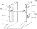
Example 1: referring to fig. 1-5, a material receiving mechanism of a rotary press comprises a base 1, wherein an installation frame 2 is arranged at the upper end of the base 1, a buffering slope 3 is arranged at the outer side of the installation frame 2, an elevating mechanism 4 and a movable frame 5 are arranged inside the installation frame 2, the elevating mechanism 4 comprises a chain wheel 401, a transmission chain 402, a screw rod 403, a first motor 404, a guide rail 405, a sliding block 406 and a guide rod 407, a connecting groove 6 is formed in the upper end of the buffering slope 3, a winding mechanism 7 is arranged at the upper end of the movable frame 5, the winding mechanism 7 comprises a clamping groove 701, a connecting sleeve 702, a winding roller 703 and a first friction wheel 704, a side plate 8 is arranged at the outer side of the installation frame 2, a second friction wheel 9 is arranged at the inner side of the side plate 8, a second motor 10 is arranged at the outer side of the side plate 8, and a control panel 11 is arranged at the outer side of the installation frame 2;
two mounting frames 2 are symmetrically arranged at the upper end of the base 1, and the buffer slopes 3 are of a trapezoidal structure;
two chain wheels 401 are arranged in the mounting frame 2 in a vertically rotating manner, and a transmission chain 402 is meshed and connected to the outer sides of the chain wheels 401;
the screw 403 is rotatably connected inside the mounting frame 2, the first motor 404 is fixedly mounted at the upper end of the mounting frame 2, the output end of the first motor 404 is fixedly connected with the screw 403, the first motor 404 is electrically connected with the control panel 11, the guide rail 405 is fixedly mounted inside the mounting frame 2, and the slider 406 is movably connected to the outer side of the guide rail 405;
the guide rod 407 is fixedly installed inside the installation frame 2, the sliding block 406 is fixedly connected with one end of the transmission chain 402, the movable frame 5 is movably connected to the outer side of the guide rod 407, the movable frame 5 is fixedly connected with the other end of the transmission chain 402, and the connecting groove 6 is located right below the movable frame 5;
specifically, as shown in fig. 1, 2 and 3, the first motor 404 is started through the control panel 11, the lead screw 403 is driven to rotate, the guide rail 405 guides the slider 406, the lead screw 403 drives the slider 406 to move up and down when rotating, the slider 406 drives the transmission chain 402 to move along the outer side of the sprocket 401, the transmission chain 402 drives the movable frame 5 to move along the guide bar 407, the height of the movable frame 5 is adjusted, and the movable frame 5 is moved down into the connecting groove 6 before use.
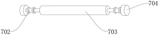
Example 2: the clamping groove 701 is formed in the upper end of the movable frame 5, the connecting sleeve 702 is sleeved in the clamping groove 701, the wind-up roll 703 is rotatably connected in the connecting sleeve 702 through a bearing, and the first friction wheel 704 is fixedly mounted at two ends of the wind-up roll 703;
the two friction wheels 9 are symmetrically arranged, the output end of the second motor 10 is fixedly connected with the second friction wheel 9, the second friction wheel 9 is attached to the first friction wheel 704, and the second motor 10 is electrically connected with the control panel 11;
specifically, as shown in fig. 1, fig. 2, fig. 4, and fig. 5, the wind-up roll 703 moves to the upper end along the inclined surface of the buffering slope 3, the connecting sleeve 702 is clamped in the clamping groove 701, the movable frame 5 supports the wind-up roll 703, after the clamping is completed, the lifting mechanism 4 drives the wind-up roll 703 to move upward until the first friction wheel 704 is attached to the second friction wheel 9, the second starting motor 10 drives the second friction wheel 9 to rotate, the second friction wheel 9 drives the first friction wheel 704 to rotate through friction force, and the wind-up roll 703 rotates along with the first friction wheel 704, so that the material receiving operation is realized.
The working principle is as follows: the first motor 404 is started through the control panel 11, the lead screw 403 is driven to rotate, the guide rail 405 plays a role in guiding the sliding block 406, when the lead screw 403 rotates, the sliding block 406 is driven to move up and down, the sliding block 406 drives the transmission chain 402 to move along the outer side of the chain wheel 401, the transmission chain 402 drives the movable frame 5 to move along the guide rod 407, the height of the movable frame 5 is adjusted, before the winding roller 703 is used, the winding roller 703 moves down into the connecting groove 6 and moves to the upper end along the inclined surface of the buffer slope 3, the connecting sleeve 702 is clamped in the clamping groove 701, the movable frame 5 plays a supporting role for the winding roller 703, after clamping is completed, the lifting mechanism 4 drives the winding roller 703 to move upwards until the first friction wheel 704 is attached to the second friction wheel 9, the second motor 10 drives the second friction wheel 9 to rotate, the second friction wheel 9 drives the first friction wheel 704 to rotate through friction force, the first friction roller 703 rotates along with the first friction wheel 704, material collection operation is realized, after material collection is completed, the lifting mechanism 4 drives the winding roller 703 to move downwards, after the movable frame 5 moves into the connecting groove 6, the connecting sleeve 702 is separated from the movable frame 5, consumption of the winding roller 703 can be reduced along the buffer slope 3.
Finally, it should be noted that: although the present invention has been described in detail with reference to the foregoing embodiments, it will be apparent to those skilled in the art that modifications may be made to the embodiments described in the foregoing embodiments, or equivalents may be substituted for elements thereof. Any modification, equivalent replacement, or improvement made within the spirit and principle of the present invention should be included in the protection scope of the present invention.
Claims (7)
1. The utility model provides a receiving agencies of rotary press, includes base (1), its characterized in that: the utility model discloses a take-up reel, including base (1), mounting bracket (2), elevating system (4), guide rail (7), winding mechanism (7), connecting sleeve (702), wind-up roll (703) and friction pulley (704), the outside of base (1) is provided with mounting bracket (2), the outside of mounting bracket (2) is provided with buffering slope (3), the inside of mounting bracket (2) is provided with elevating system (4) and adjustable shelf (5), elevating system (4) include sprocket (401), driving chain (402), lead screw (403), motor (404), guide rail (405), slider (406) and guide bar (407), spread groove (6) have been seted up to the upper end of buffering slope (3), the upper end of adjustable shelf (5) is provided with winding mechanism (7), winding mechanism (7) are including draw-in groove (701), connecting sleeve (702), wind-up roll (703) and friction pulley (704), the outside of mounting bracket (2) is provided with curb plate (8), the inboard of curb plate (8) is provided with friction pulley two (9), the outside of curb plate (8) is provided with motor two (10), the outside of mounting bracket (2) is provided with control panel (11).
2. The material receiving mechanism of a rotary press according to claim 1, characterized in that: the upper end of the base (1) of the mounting rack (2) is symmetrically provided with two buffer slopes (3) which are of a trapezoid structure.
3. The material receiving mechanism of a rotary press according to claim 1, characterized in that: the chain wheel (401) is provided with two in the inside up-and-down rotation of mounting bracket (2), the meshing of driving chain (402) is connected in the outside of chain wheel (401).
4. The material receiving mechanism of a rotary press according to claim 1, characterized in that: lead screw (403) rotate to be connected in the inside of mounting bracket (2), motor (404) fixed mounting is in the upper end of mounting bracket (2), the output and lead screw (403) fixed connection of motor (404), motor (404) is electric connection with control panel (11), guide rail (405) fixed mounting is in the inside of mounting bracket (2), slider (406) swing joint is in the outside of guide rail (405).
5. The material receiving mechanism of a rotary press according to claim 1, characterized in that: guide bar (407) fixed mounting is inside mounting bracket (2), the one end fixed connection of slider (406) and driving chain (402), adjustable shelf (5) swing joint is in the outside of guide bar (407), the other end fixed connection of adjustable shelf (5) and driving chain (402), spread groove (6) are located adjustable shelf (5) under.
6. The material receiving mechanism of a rotary press according to claim 1, characterized in that: the winding device is characterized in that the clamping groove (701) is formed in the upper end of the movable frame (5), the connecting sleeve (702) is sleeved inside the clamping groove (701), the winding roller (703) is rotatably connected inside the connecting sleeve (702) through a bearing, and the first friction wheel (704) is fixedly installed at two ends of the winding roller (703).
7. The material receiving mechanism of a rotary press according to claim 1, characterized in that: the two friction wheels (9) are symmetrically arranged, the output end of the second motor (10) is fixedly connected with the second friction wheel (9), the second friction wheel (9) is attached to the first friction wheel (704), and the second motor (10) is electrically connected with the control panel (11).
Priority Applications (1)
| Application Number | Priority Date | Filing Date | Title |
|---|---|---|---|
| CN202221190405.2U CN217780220U (en) | 2022-05-18 | 2022-05-18 | Receiving agencies of rotary press |
Applications Claiming Priority (1)
| Application Number | Priority Date | Filing Date | Title |
|---|---|---|---|
| CN202221190405.2U CN217780220U (en) | 2022-05-18 | 2022-05-18 | Receiving agencies of rotary press |
Publications (1)
| Publication Number | Publication Date |
|---|---|
| CN217780220U true CN217780220U (en) | 2022-11-11 |
Family
ID=83910180
Family Applications (1)
| Application Number | Title | Priority Date | Filing Date |
|---|---|---|---|
| CN202221190405.2U Active CN217780220U (en) | 2022-05-18 | 2022-05-18 | Receiving agencies of rotary press |
Country Status (1)
| Country | Link |
|---|---|
| CN (1) | CN217780220U (en) |
-
2022
- 2022-05-18 CN CN202221190405.2U patent/CN217780220U/en active Active
Similar Documents
| Publication | Publication Date | Title |
|---|---|---|
| CN217589969U (en) | Cable erecting device for coal mine electromechanical installation | |
| CN217780220U (en) | Receiving agencies of rotary press | |
| CN2871199Y (en) | Digital printer | |
| CN219859621U (en) | Label sticker processing auxiliary stay frame | |
| CN212194641U (en) | Printing roller adjusting device for printing machine | |
| CN213035469U (en) | Digital printing machine of stable operation | |
| CN219256835U (en) | Digital environment-friendly printing device | |
| CN1978195A (en) | Digital-code printer | |
| CN215283978U (en) | A steady speed printing chromatography mechanism for printing machine | |
| CN218052830U (en) | Slitting device of rotary printing machine | |
| CN217577528U (en) | Paper pressing device for paper printing machine | |
| CN219338906U (en) | Offset press convenient to continuous printing | |
| CN215153016U (en) | Feeding device of full-automatic printing machine | |
| CN212668721U (en) | Adjustable tensioning formula printing machine | |
| CN218261066U (en) | Winding mechanism of digital printing machine | |
| CN220332245U (en) | Printing roller adjusting structure | |
| CN215397590U (en) | Cam positioning and lifting device of screen printing machine | |
| CN214692317U (en) | Auxiliary printed matter guide mechanism for printing machine | |
| CN211363927U (en) | Package printing device | |
| CN220262369U (en) | Printing laminating machine | |
| CN216033122U (en) | Screen frame height position adjusting device of screen printing machine | |
| CN219214438U (en) | Printing machine feeding equipment with cleaning function | |
| CN220198901U (en) | Printer adjustable platform | |
| CN218289768U (en) | Loading attachment for gravure press | |
| CN218968320U (en) | Positioning structure of printing machine |
Legal Events
| Date | Code | Title | Description |
|---|---|---|---|
| GR01 | Patent grant | ||
| GR01 | Patent grant |