CN217756154U - Pneumatic material pressing one-way conveying device - Google Patents
Pneumatic material pressing one-way conveying device Download PDFInfo
- Publication number
- CN217756154U CN217756154U CN202221543417.9U CN202221543417U CN217756154U CN 217756154 U CN217756154 U CN 217756154U CN 202221543417 U CN202221543417 U CN 202221543417U CN 217756154 U CN217756154 U CN 217756154U
- Authority
- CN
- China
- Prior art keywords
- nip roll
- connecting rod
- material pressing
- conveying device
- way
- Prior art date
- Legal status (The legal status is an assumption and is not a legal conclusion. Google has not performed a legal analysis and makes no representation as to the accuracy of the status listed.)
- Active
Links
Images

Landscapes
- Rollers For Roller Conveyors For Transfer (AREA)
Abstract
Pneumatic material one-way conveyor presses relates to material transport technical field, and it includes two spinal branch framves of difference fixed mounting in band conveyer both sides, be connected with a back shaft between two spinal branch framves, rotationally be connected with two connecting plates on the back shaft, fixedly connected with material pressing roller dabber between two connecting plates, material pressing roller spindle cover is equipped with the nip roll, the nip roll passes through one-way bearing and spindle connection in order to carry out single direction rotation at the nip roll spindle, the connecting rod can be dismantled and be connected with to the connecting rod, band conveyer's both sides still articulate respectively has a cylinder, the one end of cylinder piston rod is articulated with the connecting rod. The utility model discloses can easily lift up and put down the nip rolls, alleviate intensity of labour, avoid the film to skid backward simultaneously.
Description
Technical Field
The utility model relates to a technical field is carried to the material, especially indicates a pneumatic material one-way conveyor that presses.
Background
When a common belt conveyor conveys a film, a pressure roller is required to be arranged above a conveying belt to apply certain pressure to a rubber material, so that the instability of a conveying path of the film is avoided, the weight of the pressure roller is generally heavier, the pressure roller is mainly fixedly arranged above the conveying belt in a threaded connection mode, the pressure roller is required to be detached and lifted up when new film raw materials are conveyed again each time, the pressure roller is put down and fixedly arranged after the film passes through the lower part, the process is very inconvenient, the heavier pressure roller also brings great work burden to operators, the labor intensity is very high, and secondly, as some belt conveyors are required to be obliquely arranged, the pressure roller is easy to reverse to a certain degree under the influence of the self gravity of the film, so that the film slips backwards.
SUMMERY OF THE UTILITY MODEL
An object of the utility model is to provide a pneumatic one-way conveyor that presses material can easily lift up and put down the nip rolls, alleviates intensity of labour, avoids the film to skid backward simultaneously.
In order to solve the technical problem, the utility model discloses a following technical scheme: the utility model provides a pneumatic material one-way conveyor presses, includes the two spinal branch framves of difference fixed mounting in band conveyer both sides, be connected with a back shaft between the two spinal branch framves, rotationally be connected with two connecting plates on the back shaft, fixedly connected with material pressing roller dabber between two connecting plates, material pressing roller spindle cover is equipped with the nip roll, the nip roll passes through one-way bearing and spindle connection in order to carry out one-way rotation at the nip roll spindle, the connecting plate can be dismantled and be connected with the connecting rod, band conveyer's both sides still articulate respectively has a cylinder, the one end and the connecting rod of cylinder piston rod are articulated.
Preferably, both ends of the support shaft are respectively provided with an external thread, the both ends of the support shaft respectively penetrate through the bracket on the corresponding side, each end of the support shaft is fastened to the bracket through two nuts, and the two nuts are respectively located on both sides of the bracket.
More preferably, one end of the connecting plate is provided with a first through hole for passing the support shaft.
More preferably, the connecting rod is vertically connected to the connecting plate by means of a screw connection.
More preferably, the fixed block is installed to the one end of cylinder piston rod, be provided with the second through-hole on the fixed block, the one end threaded connection of connecting rod has the bolt, one of them part of bolt is located the connecting rod outside and passes the second through-hole, the outer end of bolt still is equipped with the stopper that is used for preventing the fixed block and deviates from.
The beneficial effects of the utility model reside in that: promote the connecting rod upset through the cylinder, and then can lift up the connecting plate and make the connecting plate overturn round the back shaft, thereby lift up the nip roll fast, so that the film that supplies the below passes through from the conveyer belt, then cylinder piston pole returns back and to make the nip roll reset fast and press and make the film keep carrying stable on the film, whole operation process is very convenient, very big intensity of labour has alleviateed, moreover, because the nip roll is installed at the nip roll spindle through one-way bearing, therefore the nip roll can only one-way rotation, can avoid taking place the antiport and lead to the film to skid backward.
Drawings
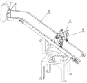
FIG. 1 is a schematic view of the overall structure of the belt conveyor of the present invention;
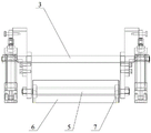
FIG. 2 is a schematic view of the overall structure in the embodiment;
fig. 3 is a perspective view of the overall structure in the embodiment.
The reference signs are:
1-belt conveyer 2-bracket 3-supporting shaft
4-connecting plate 5-material pressing roller mandrel 6-material pressing roller
7-one-way bearing 8-connecting rod 9-cylinder
10-a nut 11-a fixed block 12-a bolt.
Detailed Description
In order to facilitate understanding of those skilled in the art, the present invention will be further described with reference to the following examples and drawings, which are not intended to limit the present invention.
It should be noted that, in the present invention, unless otherwise explicitly stated or limited, terms such as "mounted," "connected," "fixed," and the like are to be construed broadly, and may be, for example, fixedly connected, detachably connected, or integrally connected. The specific meaning of the above terms in the present invention can be understood according to specific situations by those skilled in the art. Furthermore, in the present disclosure, unless explicitly stated or limited otherwise, the first feature "on" or "under" the second feature may comprise direct contact of the first and second features, or may comprise contact of the first and second features not directly but through another feature therebetween.
As shown in fig. 1-3, the pneumatic material pressing one-way conveying device comprises two supports 2 which are respectively and fixedly installed on two sides of a belt conveyor 1, a supporting shaft 3 is connected between the two supports 2, two connecting plates 4 are rotatably connected to the supporting shaft 3, a material pressing roller mandrel 5 is fixedly connected between the two connecting plates 4, a material pressing roller 6 is sleeved on the material pressing roller mandrel 5, the material pressing roller 6 is connected with the material pressing roller mandrel 5 through a one-way bearing 7 to rotate on the material pressing roller mandrel 5 in a one-way mode, a connecting rod 8 is detachably connected to the connecting plates 4, two sides of the belt conveyor 1 are respectively hinged to a cylinder 9, and one end of a piston rod of the cylinder 9 is hinged to the connecting rod 8.
Preferably, both ends of the supporting shaft 3 are respectively provided with an external thread, both ends of the supporting shaft 3 respectively penetrate through the bracket 2 on the corresponding side, each end of the supporting shaft 3 is fastened on the bracket 2 through two nuts 10, the two nuts 10 are respectively located on both sides of the bracket 2, and the two nuts 10 can respectively abut against both side surfaces of the bracket 2 after being screwed, so that the supporting shaft 3 can be stably kept on the bracket 2, the stability of the device is improved, and the disassembly and the assembly are also facilitated.
As more preferably, one end of the connecting plate 4 is provided with a first through hole for passing the supporting shaft 3 therethrough, and during the assembly of the device, the supporting shaft 3 may be passed through the first through holes of the two connecting plates 4 before being coupled to the brackets 2, and then the supporting shaft 3 is coupled between the two brackets 2, which is very simple and convenient.
More preferably, the connecting rod 8 is vertically connected to the connecting plate 4 through a threaded connection, which also facilitates the detachable connection between the connecting rod 8 and the connecting plate 4.
In addition, in this embodiment, a fixed block 11 is installed at one end of a piston rod of the cylinder 9, a second through hole is formed in the fixed block 11, a bolt 12 is connected to one end of the connecting rod 8 through threads, one part of the bolt 12 is located outside the connecting rod 8 and penetrates through the second through hole, a limiting block used for preventing the fixed block 11 from being disengaged is further arranged at the outer end of the bolt 12, and when the assembling is performed, one end of the bolt 12 can penetrate through the second through hole in the fixed block 11 and is tightly connected with the connecting rod 8.
The pneumatic material pressing one-way conveying device provided by the embodiment has the working principle that: during operation, the operation of operating personnel control cylinder 9, the piston rod extension of cylinder 9 promotes the upset of connecting rod 8, connecting rod 8 then can lift up connecting plate 4 and make connecting plate 4 overturn round support shaft 3, thereby lift up nip roll 6 fast, treat that the film on the conveyer belt passes through the back from nip roll 6 below, operation cylinder 9 makes its piston rod roll back, can put down nip roll 6 and make it reset fast and press on the film, make the film keep carrying stable, whole operation process is very convenient, very big intensity of labour that has alleviateed, moreover, because nip roll 6 is installed on nip roll spindle 5 through one-way bearing 7, consequently nip roll 6 can only unidirectional rotating, can avoid taking place the antiport and lead to the film to skid backward.
It should be noted that, as those skilled in the art should understand, the above-mentioned one-way bearing 7 is a one-way bearing 7 commonly found in the prior art, and can be directly obtained on the market, since the inner ring and the outer ring of the one-way bearing 7 can only rotate relatively in a single direction, the one-way rotation of the nip roll 6 can be realized only by connecting the inner ring of the one-way bearing 7 with the nip roll mandrel 5 and connecting the outer ring of the one-way bearing 7 with the nip roll 6, and the invention point of the present application is not on the structure of the one-way bearing 7, so the existing structure of the one-way bearing 7 is not described in detail.
The pneumatic pressing one-way conveying device provided by the embodiment can reduce labor intensity, and is very practical in a common film production and conveying workshop due to the compact structure, low cost and high operation efficiency.
In order to make the skilled person more easily understand the improvement of the present invention compared with the prior art, some drawings and descriptions of the present invention have been simplified, and the above embodiment is the preferred implementation of the present invention, besides, the present invention can be implemented in other ways, and any obvious replacement is within the protection scope of the present invention without departing from the concept of the present invention.
Claims (5)
1. Pneumatic material one-way conveyor presses, its characterized in that: including two spinal branch framves (2) of difference fixed mounting in band conveyer (1) both sides, be connected with a back shaft (3) between two spinal branch framves (2), rotationally be connected with two connecting plates (4) on back shaft (3), fixedly connected with nip roll dabber (5) between two connecting plates (4), the cover is equipped with nip roll (6) on nip roll dabber (5), nip roll (6) are connected with nip roll dabber (5) through one-way bearing (7) and carry out single direction rotation on nip roll dabber (5), connecting plate (4) can be dismantled and be connected with connecting rod (8), the both sides of band conveyer (1) still articulate respectively has a cylinder (9), the one end of cylinder (9) piston rod is articulated with connecting rod (8).
2. A pneumatic material pressing one-way conveying device according to claim 1, characterized in that: the support shaft is characterized in that external threads are respectively arranged at two ends of the support shaft (3), the two ends of the support shaft (3) respectively penetrate through the support (2) on one corresponding side, each end of the support shaft (3) is fastened on the support (2) through two nuts (10), and the two nuts (10) are respectively located on two sides of the support (2).
3. The pneumatic material pressing one-way conveying device according to claim 1, characterized in that: one end of the connecting plate (4) is provided with a first through hole for the support shaft (3) to pass through.
4. The pneumatic material pressing one-way conveying device according to claim 1, characterized in that: the connecting rod (8) is vertically connected to the connecting plate (4) in a threaded connection mode.
5. The pneumatic swaging one-way conveying device of claim 4, wherein: fixed block (11) are installed to the one end of cylinder (9) piston rod, be provided with the second through-hole on fixed block (11), the one end threaded connection of connecting rod (8) has bolt (12), one of them part of bolt (12) is located connecting rod (8) outside and passes the second through-hole, the outer end of bolt (12) still is equipped with the stopper that is used for preventing that fixed block (11) from deviating from.
Priority Applications (1)
| Application Number | Priority Date | Filing Date | Title |
|---|---|---|---|
| CN202221543417.9U CN217756154U (en) | 2022-06-20 | 2022-06-20 | Pneumatic material pressing one-way conveying device |
Applications Claiming Priority (1)
| Application Number | Priority Date | Filing Date | Title |
|---|---|---|---|
| CN202221543417.9U CN217756154U (en) | 2022-06-20 | 2022-06-20 | Pneumatic material pressing one-way conveying device |
Publications (1)
| Publication Number | Publication Date |
|---|---|
| CN217756154U true CN217756154U (en) | 2022-11-08 |
Family
ID=83895050
Family Applications (1)
| Application Number | Title | Priority Date | Filing Date |
|---|---|---|---|
| CN202221543417.9U Active CN217756154U (en) | 2022-06-20 | 2022-06-20 | Pneumatic material pressing one-way conveying device |
Country Status (1)
| Country | Link |
|---|---|
| CN (1) | CN217756154U (en) |
-
2022
- 2022-06-20 CN CN202221543417.9U patent/CN217756154U/en active Active
Similar Documents
| Publication | Publication Date | Title |
|---|---|---|
| CN104176521B (en) | A kind of Loader conveyor | |
| CN218478065U (en) | Self-correcting double-cylinder system | |
| CN207973112U (en) | A kind of belt conveyor being conveniently replaceable belt | |
| CN208932601U (en) | A kind of waterproof roll wrap-up | |
| CN217756154U (en) | Pneumatic material pressing one-way conveying device | |
| CN107790340B (en) | Composite web formula bipolar plates apply cream equipment | |
| CN210618654U (en) | Carton two-sided rubberizing machine | |
| CN207973138U (en) | A kind of light belt conveyer | |
| CN210286194U (en) | Paper pressing wheel adjusting device of rubber and flexible combined machine | |
| CN209352503U (en) | A kind of stacking scissors lift platform | |
| CN201914664U (en) | Hinged type belt pressing device for tubular belt conveyor | |
| CN208609398U (en) | A kind of double-sided symmetrical formula flexible clamping shallot conveying device | |
| CN211594202U (en) | Automatic conveying mechanism for packaging box production | |
| CN210593859U (en) | Steel sheet processing conveying equipment | |
| CN209853103U (en) | Conveying device for aluminum wing production line | |
| CN211100881U (en) | Cold-rolled strip steel flattening device | |
| CN219341075U (en) | Stainless steel strip winding machine | |
| CN214027744U (en) | Character rolling machine | |
| CN207824984U (en) | Press tearing line cutting means and its printing assembly line of application | |
| CN214731799U (en) | Independent support type pinch roller | |
| CN209815024U (en) | Pressure-adjustable floating pressing wheel device for belt conveyor | |
| CN211334702U (en) | Bud extrusion forming equipment | |
| CN208825890U (en) | A kind of fixation device for the welding of logistics roller | |
| CN218892389U (en) | Paste machine and prevent blanking conveyor | |
| CN214933216U (en) | A material frame in can inclining for screw-thread steel production |
Legal Events
| Date | Code | Title | Description |
|---|---|---|---|
| GR01 | Patent grant | ||
| GR01 | Patent grant |