CN217751663U - High accuracy paper tube cutting machine - Google Patents
High accuracy paper tube cutting machine Download PDFInfo
- Publication number
- CN217751663U CN217751663U CN202221219467.1U CN202221219467U CN217751663U CN 217751663 U CN217751663 U CN 217751663U CN 202221219467 U CN202221219467 U CN 202221219467U CN 217751663 U CN217751663 U CN 217751663U
- Authority
- CN
- China
- Prior art keywords
- fixedly connected
- paper tube
- threaded rod
- block
- motor
- Prior art date
- Legal status (The legal status is an assumption and is not a legal conclusion. Google has not performed a legal analysis and makes no representation as to the accuracy of the status listed.)
- Active
Links
- 238000005192 partition Methods 0.000 claims description 3
- 238000003466 welding Methods 0.000 claims 1
- 239000010445 mica Substances 0.000 description 2
- 229910052618 mica group Inorganic materials 0.000 description 2
- 239000007787 solid Substances 0.000 description 2
- 230000004075 alteration Effects 0.000 description 1
- 230000009286 beneficial effect Effects 0.000 description 1
- 230000007547 defect Effects 0.000 description 1
- 238000010586 diagram Methods 0.000 description 1
- 238000004519 manufacturing process Methods 0.000 description 1
- 239000000463 material Substances 0.000 description 1
- 238000000034 method Methods 0.000 description 1
- 238000012986 modification Methods 0.000 description 1
- 230000004048 modification Effects 0.000 description 1
- 238000004806 packaging method and process Methods 0.000 description 1
- 238000006467 substitution reaction Methods 0.000 description 1
Images


Landscapes
- Making Paper Articles (AREA)
Abstract
The utility model discloses a high accuracy paper tube cutting machine, comprises a workbench, first standing groove, second standing groove have been seted up to the inside of workstation, the first motor of the inside fixedly connected with of first standing groove, the first threaded rod of the output shaft fixedly connected with of first motor, the surface threaded connection of first threaded rod has first screw thread piece, the upper end fixedly connected with movable block of first screw thread piece, the upper end fixedly connected with fixed block of workstation, the equal fixedly connected with upper fixed plate in one side of movable block, fixed block, bottom plate, the first electric putter of upper fixed plate's upper end fixedly connected with, first electric putter's lower extreme fixedly connected with upper fixed ring. The utility model discloses in, through setting up first motor, first threaded rod, first thread piece, drive the movable block and remove, through setting up first electric putter, upper fixed ring, lower fixed ring, can fix the paper tube of different specifications.
Description
Technical Field
The utility model relates to a cutting machine technical field especially relates to a high accuracy paper tube cutting machine.
Background
A splitting machine is a mechanical device for splitting wide paper, mica tapes or films into a plurality of narrow materials, and is commonly used for paper making machinery, wire and cable mica tapes and printing and packaging machinery. The paper tube is a tubular object processed by paper, most of the paper tubes are spiral paper tubes and seamless paper tubes, and a splitting machine is required to split the paper tubes during production of the paper tubes.
However, the conventional paper tube splitting machine is inconvenient to fix paper tubes of different specifications, and the cutting knife of the paper tube splitting machine is fixed in position, so that the cutting length of the paper tubes cannot be adjusted with high precision, and the application range of the paper tube splitting machine is limited.
The applicant is applying the utility model discloses the time, through the retrieval, discover that chinese patent discloses "a high accuracy paper tube cutting machine", its application number is "CN201922044901.1", this patent is mainly corresponding with first fixed pipe through the fixed pipe of second, can fix the paper tube, prevent to cut in-process paper tube roll, scale fixed mounting is at the top of mounting panel, improve the cutting precision, pneumatic cylinder fixed mounting is on the support, dead lever fixed mounting is on the output shaft of pneumatic cylinder, cutting knife fixed mounting is in the bottom of dead lever, can cut the paper tube. In contrast, the utility model, through setting the first motor, the first threaded rod and the first threaded block, drives the moving block to move, through setting the first electric push rod, the upper fixing ring and the lower fixing ring, the paper tubes with different specifications can be fixed; through setting up second motor, second threaded rod, second thread piece, the drive removes the frame and removes, and then drives the cutting knife and remove, adjusts the cutting length of paper tube, and application scope is wide.
SUMMERY OF THE UTILITY MODEL
The utility model aims at solving the defects existing in the prior art and providing a high-precision paper tube splitting machine.
In order to achieve the above purpose, the utility model adopts the following technical scheme: a high-precision paper tube splitting machine comprises a workbench, wherein a first placing groove and a second placing groove are formed in the workbench, a first motor is fixedly connected to the interior of the first placing groove, a first threaded rod is fixedly connected to an output shaft of the first motor, a first threaded block is in threaded connection with the outer surface of the first threaded rod, a moving block is fixedly connected to the upper end of the first threaded block, a fixed block is fixedly connected to the upper end of the workbench, an upper fixed plate and a lower fixed plate are fixedly connected to one side of each of the moving block and the fixed block, a first electric push rod is fixedly connected to the upper end of the upper fixed plate, an upper fixing ring is fixedly connected to the lower end of the first electric push rod, a fixed column is fixedly connected to the upper end of the lower fixed plate, and a lower fixing ring is fixedly connected to the upper end of the fixed column;
the utility model discloses a cutting tool, including workstation, second standing groove, the inside symmetry of second standing groove is provided with the second motor, the output shaft fixedly connected with second threaded rod of second motor, the surface threaded connection of second threaded rod has second screw thread piece, the upper end fixedly connected with of second screw thread piece removes the frame, remove one side fixedly connected with second electric putter of frame, one side fixedly connected with cutting knife of second electric putter, one side of workstation is provided with the scale mark.
As a further description of the above technical solution:
one side of first threaded rod rotates and is connected with first bearing, one side fixed connection of first bearing is in the inner wall of workstation.
As a further description of the above technical solution:
the lower end of the first thread block is connected with the inner bottom wall of the workbench in a sliding mode.
As a further description of the above technical solution:
one side of the second threaded rod is rotatably connected with a second bearing, and a partition board is fixedly connected inside the second placing groove.
As a further description of the above technical solution:
one side of the second bearing is fixedly connected with the side wall of the partition plate.
As a further description of the above technical solution:
the lower end of the second thread block is connected with the inner bottom wall of the workbench in a sliding mode.
As a further description of the above technical solution:
one side of the movable frame is fixedly connected with a pointer.
As a further description of the above technical solution:
the lower end of the workbench is fixedly connected with a bottom column.
The utility model discloses following beneficial effect has:
1. compared with the prior art, this high accuracy paper tube cutting machine through setting up first motor, first threaded rod, first thread piece, drives the movable block and removes, through setting up first electric putter, upper fixed ring, lower fixed ring, can fix the paper tube of different specifications.
2. Compared with the prior art, this high accuracy paper tube cutting machine through setting up second motor, second threaded rod, second thread piece, drives and removes the frame and remove, and then drives the cutting knife and remove, adjusts the cutting length of paper tube, and application scope is wide.
Drawings
Fig. 1 is a schematic structural view of a high-precision paper tube splitting machine provided by the present invention;
fig. 2 is a front view of a high-precision paper tube splitting machine provided by the present invention;
fig. 3 is a top view of a moving frame of a high-precision paper tube splitting machine according to the present invention;
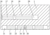
fig. 4 is the utility model provides an inner structure schematic diagram of workstation of high accuracy paper tube cutting machine.
Wherein, 1, a workbench; 2. a bottom pillar; 3. a moving block; 4. a fixed block; 5. a first electric push rod; 6. an upper fixing plate; 7. an upper fixing ring; 8. a lower fixing ring; 9. fixing a column; 10. a lower fixing plate; 11. scale lines; 12. a pointer; 13. a movable frame; 14. a second electric push rod; 15. a cutting knife; 16. a first bearing; 17. a first threaded rod; 18. a first thread block; 19. a first placing groove; 20. a first motor; 21. a second motor; 22. a second placing groove; 23. a second thread block; 24. a second threaded rod; 25. a second bearing; 26. a separator.
Detailed Description
The technical solutions in the embodiments of the present invention will be described clearly and completely with reference to the accompanying drawings in the embodiments of the present invention, and it is obvious that the described embodiments are only some embodiments of the present invention, not all embodiments. Based on the embodiments in the present invention, all other embodiments obtained by a person skilled in the art without creative work belong to the protection scope of the present invention.
Referring to fig. 1-4, the present invention provides an embodiment: a high-precision paper tube splitting machine comprises a workbench 1, wherein a first placing groove 19 and a second placing groove 22 are formed in the workbench 1, a first motor 20 is fixedly connected to the inside of the first placing groove 19, a first threaded rod 17 is fixedly connected to an output shaft of the first motor 20, a first threaded block 18 is in threaded connection with the outer surface of the first threaded rod 17, a movable block 3 is fixedly connected to the upper end of the first threaded block 18, the movable block 3 is driven to move by the arrangement of the first motor 20, the first threaded rod 17 and the first threaded block 18, a fixed block 4 is fixedly connected to the upper end of the workbench 1, the movable block 3 and one side of the fixed block 4 are fixedly connected with an upper fixed plate 6 and a lower fixed plate 10, a first electric push rod 5 is fixedly connected to the upper end of the upper fixed plate 6, an upper fixing ring 7 is fixedly connected to the lower end of the first electric push rod 5, a fixed ring 9 is fixedly connected to the upper end of the lower fixed plate 10, a lower fixing ring 8 is fixedly connected to the upper end of the fixed ring 9, and paper tubes of different specifications can be fixed by the arrangement of the first electric push rod 5, the upper fixed ring 7 and the lower fixing ring 8;
the second standing groove 22 has been seted up to workstation 1's inside, the inside symmetry of second standing groove 22 is provided with second motor 21, the output shaft fixedly connected with second threaded rod 24 of second motor 21, the surface threaded connection of second threaded rod 24 has second screw block 23, the upper end fixedly connected with of second screw block 23 removes frame 13, through setting up second motor 21, second threaded rod 24, second screw block 23, drive and remove frame 13 and remove, and then drive cutting knife 15 and remove, adjust the cutting length of paper tube, application scope is wide, one side fixedly connected with second electric putter 14 of removing frame 13, one side fixedly connected with cutting knife 15 of second electric putter 14, through second electric putter 14, can drive cutting knife 15 and remove to paper tube department, cut the paper tube, one side of workstation 1 is provided with scale mark 11, through setting up scale mark 11, improve cutting accuracy.
One side of first threaded rod 17 is rotated and is connected with first bearing 16, one side fixed connection of first bearing 16 is in the inner wall of workstation 1, the lower extreme of first screw block 18 and the interior diapire sliding connection of workstation 1, one side of second threaded rod 24 is rotated and is connected with second bearing 25, the inside fixedly connected with baffle 26 of second standing groove 22, one side fixed connection of second bearing 25 is in the lateral wall of baffle 26, the lower extreme of second screw block 23 and the interior diapire sliding connection of workstation 1, one side fixedly connected with pointer 12 of removal frame 13, through setting up pointer 12, be convenient for observe the position of locating of removal frame 13, the lower extreme fixedly connected with sill pillar 2 of workstation 1, through setting up sill pillar 2, support the cutting machine.
The working principle is as follows: this high accuracy paper tube cutting machine, when using, with cutting machine intercommunication external power supply, place the paper tube in lower solid fixed ring 8 top, start first electric putter 5, first electric putter 5 drives solid fixed ring 7 and descends, fix the paper tube, when the paper tube is shorter, start first motor 20, first motor 20 drives first threaded rod 17 and rotates, first threaded rod 17 drives first thread piece 18 and removes, first thread piece 18 drives movable block 3 and removes, and then fixes shorter paper tube, through starting second motor 21, second motor 21 drives second threaded rod 24 and rotates, second threaded rod 24 drives second thread piece 23 and removes, and then drive and remove frame 13 and remove, through observing pointer 12 and scale mark 11, and then adjust the position that removes frame 13, start second electric putter 14, cutting knife 15, second electric putter 14 drives cutting knife 15 and removes, cut the paper tube.
Although embodiments of the present invention have been shown and described, it will be appreciated by those skilled in the art that changes, modifications, substitutions and alterations can be made in these embodiments without departing from the principles and spirit of the invention, the scope of which is defined in the appended claims and their equivalents.
Claims (8)
1. The utility model provides a high accuracy paper tube cutting machine, includes workstation (1), its characterized in that: a first placing groove (19) and a second placing groove (22) are formed in the workbench (1), a first motor (20) is fixedly connected to the interior of the first placing groove (19), a first threaded rod (17) is fixedly connected to an output shaft of the first motor (20), a first threaded block (18) is in threaded connection with the outer surface of the first threaded rod (17), a moving block (3) is fixedly connected to the upper end of the first threaded block (18), a fixed block (4) is fixedly connected to the upper end of the workbench (1), an upper fixed plate (6) and a lower fixed plate (10) are fixedly connected to one side of the moving block (3) and one side of the fixed block (4), a first electric push rod (5) is fixedly connected to the upper end of the upper fixed plate (6), an upper fixing ring (7) is fixedly connected to the lower end of the first electric push rod (5), a fixed column (9) is fixedly connected to the upper end of the lower fixed plate (10), and a lower fixing ring (8) is fixedly connected to the upper end of the fixed column (9);
the utility model discloses a hydraulic pressure welding machine, including workstation (1), workstation, output shaft fixedly connected with second threaded rod (24), the outer surface threaded connection of second threaded rod (24), the upper end fixedly connected with of second threaded rod (23) removes frame (13), one side fixedly connected with second electric putter (14) of removing frame (13), one side fixedly connected with cutting knife (15) of second electric putter (14), one side of workstation (1) is provided with scale mark (11), the inside symmetry of second standing groove (22) is provided with second motor (21), output shaft fixedly connected with second threaded rod (24) of second motor (21), the surface threaded connection of second threaded rod (24) has second screw thread piece (23).
2. The high-precision paper tube splitting machine as claimed in claim 1, wherein: one side of the first threaded rod (17) is rotatably connected with a first bearing (16), and one side of the first bearing (16) is fixedly connected to the inner wall of the workbench (1).
3. The high-precision paper tube splitting machine as claimed in claim 1, wherein: the lower end of the first thread block (18) is connected with the inner bottom wall of the workbench (1) in a sliding way.
4. The high-precision paper tube splitting machine as claimed in claim 1, wherein: one side of the second threaded rod (24) is rotatably connected with a second bearing (25), and a partition plate (26) is fixedly connected inside the second placing groove (22).
5. The high-precision paper tube splitting machine according to claim 4, wherein: one side of the second bearing (25) is fixedly connected with the side wall of the clapboard (26).
6. The high-precision paper tube splitting machine according to claim 1, characterized in that: the lower end of the second thread block (23) is connected with the inner bottom wall of the workbench (1) in a sliding manner.
7. The high-precision paper tube splitting machine as claimed in claim 1, wherein: one side of the movable frame (13) is fixedly connected with a pointer (12).
8. The high-precision paper tube splitting machine according to claim 1, characterized in that: the lower end of the workbench (1) is fixedly connected with a bottom column (2).
Priority Applications (1)
| Application Number | Priority Date | Filing Date | Title |
|---|---|---|---|
| CN202221219467.1U CN217751663U (en) | 2022-05-20 | 2022-05-20 | High accuracy paper tube cutting machine |
Applications Claiming Priority (1)
| Application Number | Priority Date | Filing Date | Title |
|---|---|---|---|
| CN202221219467.1U CN217751663U (en) | 2022-05-20 | 2022-05-20 | High accuracy paper tube cutting machine |
Publications (1)
| Publication Number | Publication Date |
|---|---|
| CN217751663U true CN217751663U (en) | 2022-11-08 |
Family
ID=83886786
Family Applications (1)
| Application Number | Title | Priority Date | Filing Date |
|---|---|---|---|
| CN202221219467.1U Active CN217751663U (en) | 2022-05-20 | 2022-05-20 | High accuracy paper tube cutting machine |
Country Status (1)
| Country | Link |
|---|---|
| CN (1) | CN217751663U (en) |
Cited By (1)
| Publication number | Priority date | Publication date | Assignee | Title |
|---|---|---|---|---|
| CN116786593A (en) * | 2023-06-12 | 2023-09-22 | 新疆八一钢铁股份有限公司 | Cutting device for rolling rod and wire rod |
-
2022
- 2022-05-20 CN CN202221219467.1U patent/CN217751663U/en active Active
Cited By (1)
| Publication number | Priority date | Publication date | Assignee | Title |
|---|---|---|---|---|
| CN116786593A (en) * | 2023-06-12 | 2023-09-22 | 新疆八一钢铁股份有限公司 | Cutting device for rolling rod and wire rod |
Similar Documents
| Publication | Publication Date | Title |
|---|---|---|
| CN107984013B (en) | A milling cutter for marking workpieces | |
| CN205949970U (en) | Bellows cutting device | |
| CN109158647A (en) | A kind of pipe fitting drilling specialized nc machine tool | |
| CN106270740A (en) | A kind of corrugated tube cutter sweep | |
| CN118437966B (en) | A stainless steel pipe cutting machine tool | |
| CN112404515A (en) | Processing device for tubular workpiece | |
| CN116441631B (en) | Adjustable fixing equipment for cutting raw materials for die machining | |
| CN117445050A (en) | A corrugated pipe cutting machine and its traction mechanism | |
| CN215790021U (en) | Cutting equipment is used in PE membrane blowing production | |
| CN116475439A (en) | A high-precision turning device for external thread of long rod | |
| CN213163217U (en) | High-efficient perforating device of metal work piece | |
| CN222448337U (en) | A digital hole reaming machine that is convenient for workpiece surface | |
| CN223718468U (en) | Sunshade support production equipment | |
| CN218425967U (en) | A horizontal sawing machine for the production of inspection tools | |
| CN221694950U (en) | Continuous reamer for hardware part machining | |
| CN216326445U (en) | Multifunctional full-automatic production equipment | |
| CN219004818U (en) | Chamfering machine for pipe parts | |
| CN221210088U (en) | Circular tube cutting auxiliary table for metal machining manufacturing | |
| CN221734939U (en) | A slotting device for aluminum template processing | |
| CN221159513U (en) | A stainless steel coil cutting device | |
| CN217665673U (en) | Prevent that mould from inserting accurate structure of hindering | |
| CN215237996U (en) | Punching device for machining bridge-cutoff aluminum doors and windows | |
| CN217433199U (en) | Fixing device of medium aluminium machine | |
| CN221516203U (en) | Positioning and guiding device for deep hole drilling machine | |
| CN222660278U (en) | Steel pipe cutting machine |
Legal Events
| Date | Code | Title | Description |
|---|---|---|---|
| GR01 | Patent grant | ||
| GR01 | Patent grant |