CN217750513U - Tool clamp for machining motor shaft - Google Patents
Tool clamp for machining motor shaft Download PDFInfo
- Publication number
- CN217750513U CN217750513U CN202222028876.XU CN202222028876U CN217750513U CN 217750513 U CN217750513 U CN 217750513U CN 202222028876 U CN202222028876 U CN 202222028876U CN 217750513 U CN217750513 U CN 217750513U
- Authority
- CN
- China
- Prior art keywords
- motor shaft
- close
- spacing
- fixing
- seat
- Prior art date
- Legal status (The legal status is an assumption and is not a legal conclusion. Google has not performed a legal analysis and makes no representation as to the accuracy of the status listed.)
- Active
Links
Images


Landscapes
- Jigs For Machine Tools (AREA)
Abstract
The utility model discloses a frock clamp is used in motor shaft processing, which comprises a fixed base, the upper surface of fixing base is close to right-hand member fixed mounting and has spacing seat, and the spacing motor shaft of having placed of the upper surface intermediate position of spacing seat, the upper surface of spacing seat still is provided with the hold-down mechanism who compresses tightly the motor shaft, hold-down mechanism can compress tightly altitude mixture control, the upper surface of fixing base is close to the left end and is provided with and carries out spacing locating plate to the motor shaft left end, the locating plate can carry out the position control of left and right sides direction, when fixing a position the clamping to the motor shaft, place it and carry out spacing placing on spacing seat, and make the one end of motor shaft just carry out position determination on the locating plate, thereby compress tightly fixed the completion through hold-down mechanism and add the location clamping to the motor shaft, make the location clamping of motor shaft more convenient.
Description
Technical Field
The utility model relates to a motor shaft processing technology field specifically is a frock clamp is used in motor shaft processing.
Background
When the motor shaft is produced and processed, the motor shaft is machined and formed through a lathe, and then the end of the motor shaft needs to be subjected to keyway milling.
When a traditional motor shaft is subjected to keyway milling processing, the motor shaft needs to be clamped and fixed on a workbench of a milling machine through a bench vice, and the motor shaft can be processed only by tool setting during keyway milling, and cannot be quickly positioned and clamped by the motor shaft due to the fact that the next motor shaft needs to be subjected to tool setting again during processing.
SUMMERY OF THE UTILITY MODEL
In order to solve the problem of the existence, the application provides a frock clamp for motor shaft processing, adopts following technical scheme:
the utility model provides a frock clamp for motor shaft processing, includes the fixing base, and the upper surface of fixing base is close to right-hand member fixed mounting has spacing seat, and the motor shaft has been placed to the upper surface intermediate position of spacing seat spacing, and the upper surface of spacing seat still is provided with the hold-down mechanism who compresses tightly the motor shaft, and hold-down mechanism can compress tightly altitude mixture control, and the upper surface of fixing base is close to the left end and is provided with and carries out spacing locating plate to the motor shaft left end, and the locating plate can carry out the position control of left right direction.
Through adopting above-mentioned technical scheme, when fixing a position the clamping to the motor shaft, place it and carry out spacing placing on spacing seat to make the one end of motor shaft closely carry out position determination on the locating plate, thereby compress tightly fixed the completion through hold-down mechanism and fix a position the clamping when processing the motor shaft, make the location clamping of motor shaft more convenient.
Preferably, a V-shaped groove is formed in the middle of the upper surface of the limiting seat, a fixing rod which is connected with the pressing mechanism in a matched mode is arranged on the upper surface of the limiting seat close to the rear end, and a threaded hole is formed in the upper surface of the limiting seat close to the front end.
Through adopting above-mentioned technical scheme, spacing seat carries out spacing the placing through V type groove to the motor shaft to carry out fixed connection through dead lever and hold-down mechanism.
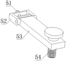
Preferably, the pressing mechanism comprises an adjusting sleeve sleeved on the fixing rod, a fixing screw is screwed on the rear side of the adjusting sleeve, a pressing rod is rotatably connected on the front side of the adjusting sleeve, and a pressing screw screwed in the threaded hole is inserted in the position, close to the front end, of the pressing rod.
Through adopting above-mentioned technical scheme, hold-down mechanism is through adjusting the cover and overlapping on the dead lever to carry out the fixed realization of locking through the set screw and with the fixed connection of dead lever, and compress tightly fixedly through the depression bar to the motor shaft.
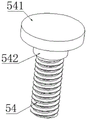
Preferably, the upper end of the compression screw is provided with a cylindrical stop block, and the upper end of the stop block is provided with a rotating handle.
By adopting the technical scheme, the rotating handle is utilized to screw the compression screw so as to screw the compression screw in the threaded hole, and the compression rod is used for compressing and fixing the motor shaft.
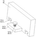
The preferred, both ends position all is provided with the guide slot of T type around the downside of locating plate is close to, and the last fixed surface of fixing base installs two and guide slot complex guide rails, and the left side of locating plate is close to the lower extreme and is provided with the locking piece, and has twisted locking screw on the locking piece vertically soon.
Through adopting above-mentioned technical scheme, thereby the locating plate passes through the position control of direction draw-in groove card realization left right direction on the guide rail to realize the location position control to the motor shaft.
Preferably, the fixing seat is provided with mounting blocks near the four corners, and the mounting blocks are provided with U-shaped openings.
Through adopting above-mentioned technical scheme, the fixing base compresses tightly the cooperation through the clamp plate screw rod on installation piece and the milling machine frock platform.
Compared with the prior art, the beneficial effects of the utility model are that:
1. when the motor shaft is positioned and clamped, the motor shaft is placed on the limiting seat for limiting, one end of the motor shaft is abutted against the positioning plate for position determination, and is pressed and fixed through the pressing mechanism so as to complete the positioning and clamping during the processing of the motor shaft, so that the positioning and clamping of the motor shaft are more convenient;
2. the positioning plate capable of being adjusted in the left-right direction and the pressing mechanism capable of being pressed and adjusted in height can meet the requirements for positioning and clamping of motor shafts of different sizes, and the motor shaft pressing device has good use flexibility.
Drawings
In order to more clearly illustrate the technical solution of the embodiments of the present invention, the drawings which are required to be used in the embodiments will be briefly described below, it should be understood that the following drawings only illustrate some embodiments of the present invention and therefore should not be considered as limiting the scope, and that for those skilled in the art, other related drawings can be obtained according to these drawings without inventive efforts.
Fig. 1 is a perspective view of the utility model of a tool clamp for machining a motor shaft;
fig. 2 is a schematic view of a limiting seat of the tool clamp for machining a motor shaft of the present invention;
fig. 3 is a schematic view of a pressing mechanism of the tool clamp for machining the motor shaft of the present invention;
fig. 4 is a schematic view of a pressing screw of the tool clamp for machining a motor shaft of the present invention;
fig. 5 is the utility model discloses a locating plate schematic diagram of frock clamp for motor shaft processing.
In the figure: 1. a fixed seat; 2. positioning a plate; 21. a guide clamping groove; 22. a locking block; 23. locking screws; 3. a motor shaft; 4. a limiting seat; 41. fixing the rod; 42. a V-shaped groove; 43. a threaded hole; 5. a hold-down mechanism; 51. fixing screws; 52. an adjusting sleeve; 53. a pressure lever; 54. a compression screw; 541. a handle is rotated; 542. a stopper; 6. a guide rail; 7. and (7) installing the block.
Detailed Description
To make the objects, technical solutions and advantages of the embodiments of the present invention clearer, the drawings of the embodiments of the present invention are combined to clearly and completely describe the technical solutions of the embodiments of the present invention, and obviously, the described embodiments are some embodiments of the present invention, not all embodiments. Based on the embodiments in the present invention, all other embodiments obtained by a person skilled in the art without creative work belong to the protection scope of the present invention. Thus, the following detailed description of the embodiments of the present invention, presented in the accompanying drawings, is not intended to limit the scope of the invention, as claimed, but is merely representative of selected embodiments of the invention.
Specifically, referring to fig. 2, 3 and 4, a fixing rod 41 connected and matched with the pressing mechanism 5 is disposed on the upper surface of the limiting seat 4 near the rear end, a threaded hole 43 is disposed on the upper surface of the limiting seat 4 near the front end, the pressing mechanism 5 includes an adjusting sleeve 52 sleeved on the fixing rod 41, a fixing screw 51 is screwed on the rear side of the adjusting sleeve 52, a pressing rod 53 is rotatably connected to the front side of the adjusting sleeve 52, a pressing screw 54 screwed in the threaded hole 43 is inserted through the pressing rod 53 near the front end, a cylindrical stopper 542 is disposed on the upper end of the pressing screw 54, a rotating handle 541 is disposed on the upper end of the stopper 542, the pressing rod 53 is screwed in the threaded hole 43 by screwing the rotating handle 54 so as to press and fix the motor shaft 3, the pressing mechanism 5 is sleeved on the fixing rod 41 by the adjusting sleeve 52, and is locked and fixed by the fixing screw 51 so as to fixedly connect with the fixing rod 41, and the motor shaft 3 is pressed and fixed by the pressing rod 53.
Referring to fig. 1 and 5, T-shaped guide slots 21 are respectively formed in positions, close to front and rear ends, of the lower side of the positioning plate 2, two guide rails 6 matched with the guide slots 21 are fixedly mounted on the upper surface of the fixing base 1, a locking block 22 is arranged on the left side of the positioning plate 2, close to the lower end, and a locking screw 23 is vertically screwed on the locking block 22, so that the positioning plate 2 is clamped on the guide rails 6 through the guide slots 21 to achieve position adjustment in the left-right direction, and therefore positioning position adjustment of the motor shaft 3 is achieved.
The working principle is that when the motor shaft 3 is positioned and clamped, one end of the motor shaft 3 needing key milling is placed on the right side, then the motor shaft 3 is placed in the V-shaped groove 42, the left end of the motor shaft is abutted against the positioning plate 2, then the pressing rod 53 is rotated to be pressed on the motor shaft 3, finally the pressing screw 54 penetrates through the pressing rod 53 and is screwed in the threaded hole 43, so that the pressing rod 53 presses and fixes the motor shaft 3, when the motor shaft 3 is taken out, the processed motor shaft 3 can be taken out by directly screwing and loosening the pressing screw 54, then the next motor shaft 3 penetrates between the V-shaped groove 42 and the pressing rod 53 and is abutted against the positioning plate 2, and then secondary clamping can be carried out.
The above description is only a preferred embodiment of the present invention and is not intended to limit the present invention, and various modifications and changes may be made by those skilled in the art. Any modification, equivalent replacement, or improvement made within the spirit and principle of the present invention should be included in the protection scope of the present invention.
Claims (6)
1. The utility model provides a frock clamp is used in motor shaft processing, includes fixing base (1), its characterized in that: the upper surface of fixing base (1) is close to right-hand member fixed mounting and has spacing seat (4), and the upper surface intermediate position of spacing seat (4) is spacing to have placed motor shaft (3), the upper surface of spacing seat (4) still is provided with hold-down mechanism (5) that compress tightly motor shaft (3), hold-down mechanism (5) can compress tightly altitude mixture control, the upper surface of fixing base (1) is close to the left end and is provided with and carries out spacing locating plate (2) to motor shaft (3) left end, the position control of direction about can going on in locating plate (2).
2. The tool clamp for machining the motor shaft as claimed in claim 1, wherein a V-shaped groove (42) is formed in the middle of the upper surface of the limiting seat (4), a fixing rod (41) connected and matched with the pressing mechanism (5) is arranged on the upper surface of the limiting seat (4) close to the rear end, and a threaded hole (43) is formed in the upper surface of the limiting seat (4) close to the front end.
3. The tool clamp for machining the motor shaft as claimed in claim 2, wherein the pressing mechanism (5) comprises an adjusting sleeve (52) sleeved on the fixing rod (41), a fixing screw (51) is screwed on the rear side of the adjusting sleeve (52), a pressing rod (53) is rotatably connected on the front side of the adjusting sleeve (52), and a pressing screw (54) screwed in the threaded hole (43) is inserted through the pressing rod (53) close to the front end.
4. The tool clamp for machining the motor shaft as claimed in claim 3, wherein a cylindrical stopper (542) is arranged at the upper end of the compression screw (54), and a rotating handle (541) is arranged at the upper end of the stopper (542).
5. The tool clamp for machining the motor shaft according to claim 1, wherein the lower side of the positioning plate (2) is provided with T-shaped guide clamping grooves (21) at positions close to the front end and the rear end, the upper surface of the fixing seat (1) is fixedly provided with two guide rails (6) matched with the guide clamping grooves (21), the left side of the positioning plate (2) is provided with a locking block (22) close to the lower end, and the locking block (22) is vertically screwed with a locking screw (23).
6. The tool clamp for machining the motor shaft as claimed in claim 5, wherein the fixing seat (1) is fixedly provided with mounting blocks (7) near four corners, and the mounting blocks (7) are provided with U-shaped openings.
Priority Applications (1)
| Application Number | Priority Date | Filing Date | Title |
|---|---|---|---|
| CN202222028876.XU CN217750513U (en) | 2022-08-03 | 2022-08-03 | Tool clamp for machining motor shaft |
Applications Claiming Priority (1)
| Application Number | Priority Date | Filing Date | Title |
|---|---|---|---|
| CN202222028876.XU CN217750513U (en) | 2022-08-03 | 2022-08-03 | Tool clamp for machining motor shaft |
Publications (1)
| Publication Number | Publication Date |
|---|---|
| CN217750513U true CN217750513U (en) | 2022-11-08 |
Family
ID=83880179
Family Applications (1)
| Application Number | Title | Priority Date | Filing Date |
|---|---|---|---|
| CN202222028876.XU Active CN217750513U (en) | 2022-08-03 | 2022-08-03 | Tool clamp for machining motor shaft |
Country Status (1)
| Country | Link |
|---|---|
| CN (1) | CN217750513U (en) |
-
2022
- 2022-08-03 CN CN202222028876.XU patent/CN217750513U/en active Active
Similar Documents
| Publication | Publication Date | Title |
|---|---|---|
| CN211760013U (en) | Plate positioning tool for machining center | |
| CN217750513U (en) | Tool clamp for machining motor shaft | |
| CN214322574U (en) | Clamping device of case cover for automobile | |
| CN215148855U (en) | Panel frock clamp for machining | |
| CN212665440U (en) | High-precision center frame | |
| CN115194481A (en) | High-precision end face milling and center hole drilling device for machining shaft end of ball screw | |
| CN214922543U (en) | Pneumatic clamping tool capable of machining at multiple angles | |
| CN114309846A (en) | Axle center alignment method for machining inner hole of shaft part | |
| CN209775987U (en) | Novel carpenter's carving machine | |
| CN208322797U (en) | A kind of device to drill for processing mould for automobile lock hook | |
| CN208163132U (en) | Long thimble Set and Positioning fixture | |
| CN216029501U (en) | Clamping frock and processing equipment of axle sleeve | |
| CN217702456U (en) | Machining positioning fixture | |
| CN206273454U (en) | A kind of small-sized wire cutting machine tool fixture | |
| CN213318931U (en) | CNC processing quick alignment frock | |
| CN219054098U (en) | Hardware fitting frock clamp | |
| CN110385590B (en) | Die carrier double-inclination slideway processing positioning device and processing system | |
| CN217096754U (en) | Clamping tool for aviation part machining | |
| CN216399087U (en) | Grinding machine rough blank processing fixed station | |
| CN219649700U (en) | Frock smelting tool that pure iron of electromagnetism piece was used | |
| CN216371213U (en) | Pneumatic clamping device for aluminum template | |
| CN220296027U (en) | Automatic chamfering machine | |
| CN214870022U (en) | Engine clamping device | |
| CN212526770U (en) | Semi-automatic auxiliary screw locking device | |
| CN210498789U (en) | Special tool for machining laser cutting machine parts |
Legal Events
| Date | Code | Title | Description |
|---|---|---|---|
| GR01 | Patent grant | ||
| GR01 | Patent grant |