CN217750491U - Supplementary clamping device of construction pipe fitting fluting - Google Patents
Supplementary clamping device of construction pipe fitting fluting Download PDFInfo
- Publication number
- CN217750491U CN217750491U CN202221678720.XU CN202221678720U CN217750491U CN 217750491 U CN217750491 U CN 217750491U CN 202221678720 U CN202221678720 U CN 202221678720U CN 217750491 U CN217750491 U CN 217750491U
- Authority
- CN
- China
- Prior art keywords
- fixedly connected
- plate
- base
- pipe fitting
- clamping device
- Prior art date
- Legal status (The legal status is an assumption and is not a legal conclusion. Google has not performed a legal analysis and makes no representation as to the accuracy of the status listed.)
- Active
Links
Images


Landscapes
- Placing Or Removing Of Piles Or Sheet Piles, Or Accessories Thereof (AREA)
Abstract
The utility model discloses a clamping device is assisted in building construction pipe fitting fluting, the on-line screen storage device comprises a base, two support columns of the symmetrical fixedly connected with of upside and two backup pads of base, two the equal fixedly connected with slider of lateral wall of support column, the top of base is provided with the crown plate, the rear side of crown plate is provided with the spout, two the slider all is located the inside of spout and with spout sliding connection, two the common fixedly connected with fixed plate in upper end of backup pad, the inboard circumference of fixed plate is equidistant to be provided with three grip block, be provided with the three fixture that is used for grip block centre gripping pipe fitting on the fixed plate, the upside of base is provided with the actuating mechanism who is used for driving the fixture function. The utility model has the advantages of reasonable design, the rotation of square pole has been realized to rotate through the threaded rod and make the grip block carry out the centre gripping to the pipe fitting, make things convenient for the staff to carry out the fluting processing to the pipe fitting.
Description
Technical Field
The utility model relates to a clamping device technical field especially relates to a supplementary clamping device of construction pipe fitting fluting.
Background
The building construction refers to production activities in the engineering construction implementation stage, is the construction process of various buildings, and also can be a process of changing various lines on a design drawing into a real object at a specified place.
In the in-process of construction, often can need to be used the pipe fitting and carry out the butt joint, and usually need carry out the fluting to the pipe fitting and handle, when using the machine to carry out the fluting to the pipe fitting, under the effect of external force, the pipe fitting can take place to rotate, the staff of being not convenient for handles the fluting of pipe fitting.
SUMMERY OF THE UTILITY MODEL
The utility model aims at solving the shortcoming that exists among the prior art, and the supplementary clamping device of a construction pipe fitting fluting that proposes.
In order to achieve the above purpose, the utility model adopts the following technical scheme:
the utility model provides a clamping device is assisted in construction pipe fitting fluting, includes the base, two support columns of the upside symmetry fixedly connected with and two backup pads of base, two the equal fixedly connected with slider of lateral wall of support column, the top of base is provided with the crown plate, the rear side of crown plate is provided with the spout, two the slider all be located the inside of spout and with spout sliding connection, two the common fixedly connected with fixed plate in upper end of backup pad, the inboard circumference of fixed plate is equidistant to be provided with three grip block, be provided with the three fixture that is used for grip block centre gripping pipe fitting on the fixed plate, the upside of base is provided with the actuating mechanism who is used for driving the fixture function.
Preferably, fixture includes two connecting rods of fixed connection in the fixed plate outside, two the common fixedly connected with baffle of one end of fixed plate is kept away from to the connecting rod, the upside of baffle is run through and is provided with the square bar, the upper end fixedly connected with limiting plate of square bar, the one end fixedly connected with threaded rod of limiting plate is kept away from to the square bar, the one end that the square bar was kept away from to the threaded rod runs through the fixed plate and is connected with the grip block rotation, two telescopic links of inboard fixedly connected with of fixed plate, two the flexible end of telescopic link all with grip block fixed connection, threaded rod and fixed plate threaded connection.
Preferably, the driving mechanism includes a motor fixedly connected to the upper side of the base, an output shaft of the motor is fixedly connected with a circular gear, an outer side of the ring plate is fixedly connected with a gear ring, the gear ring is engaged with the circular gear, one side of the ring plate close to the fixing plate is fixedly connected with a first bevel gear, the upper side of the baffle is rotatably connected with a second bevel gear, and the second bevel gear is engaged with the first bevel gear.
Preferably, the upper side of the base is provided with a groove, and the circular gear is located inside the groove.
Preferably, a through hole matched with the square rod is arranged on the second bevel gear in a penetrating mode, and the square rod is located inside the through hole.
Preferably, the square rod and the threaded rod are of an integral structure.
The utility model discloses possess following beneficial effect:
1. by arranging the clamping mechanism, the square rod can be rotated to drive the threaded rod to rotate, so that the threaded rod can drive the clamping plate to move towards the circle center of the fixed plate, the pipe fitting is clamped, and the grooving treatment of the pipe fitting is facilitated for workers;
2. through setting up actuating mechanism, the motor rotates and can drive the circular gear and rotate to drive the ring plate through the ring gear and rotate with first bevel gear, recycle second bevel gear and drive the square pole and rotate, the grip block of being convenient for to the pipe fitting.
Drawings
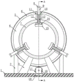
Fig. 1 is a schematic structural view of an auxiliary clamping device for grooving of a pipe fitting in building construction provided by the utility model;
FIG. 2 isbase:Sub>A schematic sectional view taken along line A-A in FIG. 1;
fig. 3 is the utility model provides a ring plate structure schematic diagram among supplementary clamping device of construction pipe fitting fluting.
In the figure: the device comprises a base 1, a support column 2, a support plate 3, a ring plate 4, a gear ring 5, a first bevel gear 6, a fixing plate 7, a limiting plate 8, a square rod 9, a second bevel gear 10, a baffle plate 11, a connecting rod 12, a threaded rod 13, a telescopic rod 14, a clamping plate 15, a motor 16, a circular gear 17, a groove 18, a sliding block 19 and a sliding groove 20.
Detailed Description
The technical solutions in the embodiments of the present invention will be described clearly and completely with reference to the accompanying drawings in the embodiments of the present invention, and it is obvious that the described embodiments are only some embodiments of the present invention, not all embodiments.
In the description of the present invention, it is to be understood that the terms "upper", "lower", "front", "rear", "left", "right", "top", "bottom", "inner", "outer", and the like indicate orientations or positional relationships based on the orientations or positional relationships shown in the drawings, and are only for convenience of description and simplicity of description, and do not indicate or imply that the device or element being referred to must have a particular orientation, be constructed and operated in a particular orientation, and therefore, should not be construed as limiting the present invention.
Referring to fig. 1-3, a supplementary clamping device of construction pipe fitting fluting, including base 1, two support columns 2 and two backup pads 3 of the symmetrical fixedly connected with of upside of base 1, the equal fixedly connected with slider 19 of lateral wall of two support columns 2, the top of base 1 is provided with crown plate 4, the rear side of crown plate 4 is provided with spout 20, spout 20 is the annular structure, two sliders 19 all are located the inside of spout 20 and with spout 20 sliding connection, the common fixedly connected with fixed plate 7 in upper end of two backup pads 3, fixed plate 7 is the annular structure, the inboard circumference of fixed plate 7 is equidistant to be provided with three grip block 15.
Be provided with three fixture that is used for grip block 15 centre gripping pipe fitting on fixed plate 7, fixture includes two connecting rods 12 of fixed connection in the fixed plate 7 outside, the common fixedly connected with baffle 11 of one end that fixed plate 7 was kept away from to two connecting rods 12, the upside of baffle 11 runs through and is provided with square pole 9, it is provided with the opening with square pole 9 looks adaptation to link up on the baffle 11, square pole 9 is located open-ended inside and with opening sliding connection, the upper end fixedly connected with limiting plate 8 of square pole 9, limiting plate 8 can avoid square pole 9 to slide, the one end fixedly connected with threaded rod 13 of limiting plate 8 is kept away from to square pole 9, square pole 9 and threaded rod 13 structure as an organic whole, threaded rod 13 keeps away from the one end of square pole 9 and runs through fixed plate 7 and is connected with grip block 15 rotation, two inboard fixedly connected with telescopic link 14 of fixed plate 7, the flexible end of two telescopic link 14 all with grip block 15 fixed connection, threaded connection 13 and fixed plate 7, it is provided with the screw hole of threaded rod 13 looks adaptation with threaded rod 13 on fixed plate 7 to link up, fixture accessible square pole 9 rotates and drives grip block 13 to rotate, thereby the direction of the fixed plate 15 realizes the centre gripping pipe fitting to the centre of centre gripping pipe fitting.
The upside of base 1 is provided with the actuating mechanism who is used for driving fixture to function, actuating mechanism includes the motor 16 of fixed connection at the base 1 upside, the output shaft fixedly connected with round gear 17 of motor 16, motor 16 can drive round gear 17 and rotate, the upside of base 1 is provided with recess 18, round gear 17 is located the inside of recess 18, the outside fixedly connected with ring gear 5 of crown plate 4, ring gear 5 meshes with round gear 17, round gear 17 rotates and can drive ring gear 5 and rotate, one side fixedly connected with first bevel gear 6 that crown plate 4 is close to fixed plate 7, crown plate 4 rotates and can drive first bevel gear 6 and rotate, the upside rotation of baffle 11 is connected with second bevel gear 10, link up on the second bevel gear 10 and be provided with the through-hole with square bar 9 looks adaptation, square bar 9 is located inside the through-hole, second bevel gear 10 meshes with first bevel gear 6, actuating mechanism drives round gear 17 through motor 16 and rotates, drive crown plate 4 and first bevel gear 6 through ring gear 5 and rotate, and utilize second bevel gear 10 to drive square bar 9 and rotate.
During operation, insert the pipe fitting between three grip blocks 15, open motor 16, motor 16 can drive the rotation of circular gear 17, drives crown plate 4 and first bevel gear 6 through ring gear 5 and rotates to utilize second bevel gear 10 to drive square pole 9 and threaded rod 13 and rotate, make threaded rod 13 drive grip block 15 and move towards the 7 centre of a circle directions of fixed plate, realize the centre gripping to the pipe fitting, make things convenient for the staff to carry out the fluting processing to the pipe fitting.
Above, only be the concrete implementation of the preferred embodiment of the present invention, but the protection scope of the present invention is not limited thereto, and any person skilled in the art is in the technical scope of the present invention, according to the technical solution of the present invention and the design of the present invention, equivalent replacement or change should be covered within the protection scope of the present invention.
Claims (6)
1. The utility model provides a clamping device is assisted in building construction pipe fitting fluting, includes base (1), its characterized in that, two support columns (2) of upside symmetry fixedly connected with and two backup pads (3) of base (1), two the equal fixedly connected with slider (19) of lateral wall of support column (2), the top of base (1) is provided with crown plate (4), the rear side of crown plate (4) is provided with spout (20), two slider (19) all are located the inside of spout (20) and with spout (20) sliding connection, two the common fixedly connected with fixed plate (7) in upper end of backup pad (3), the inboard circumference of fixed plate (7) is equidistant to be provided with three grip block (15), be provided with the three fixture who is used for grip block (15) centre gripping pipe fitting on fixed plate (7), the upside of base (1) is provided with the actuating mechanism who is used for driving the fixture function.
2. The auxiliary clamping device for grooving of building construction pipe fittings as claimed in claim 1, wherein the clamping mechanism comprises two connecting rods (12) fixedly connected to the outer side of the fixing plate (7), two connecting rods (12) are connected to one end of the fixing plate (7) away from a common fixedly connected baffle (11), a square rod (9) is arranged on the upper side of the baffle (11) in a penetrating manner, an upper end fixedly connected to a limiting plate (8) of the square rod (9), one end fixedly connected to a threaded rod (13) of the limiting plate (8) is away from the square rod (9), one end of the threaded rod (13) away from the square rod (9) penetrates through the fixing plate (7) and is rotatably connected with a clamping plate (15), two telescopic rods (14) fixedly connected to the inner side of the fixing plate (7), two telescopic ends of the telescopic rods (14) are fixedly connected with the clamping plate (15), and the threaded rod (13) is in threaded connection with the fixing plate (7).
3. The auxiliary clamping device for grooving of building construction pipes according to claim 2, wherein the driving mechanism comprises a motor (16) fixedly connected to the upper side of the base (1), an output shaft of the motor (16) is fixedly connected with a circular gear (17), a gear ring (5) is fixedly connected to the outer side of the ring plate (4), the gear ring (5) is meshed with the circular gear (17), a first bevel gear (6) is fixedly connected to one side, close to the fixing plate (7), of the ring plate (4), a second bevel gear (10) is rotatably connected to the upper side of the baffle plate (11), and the second bevel gear (10) is meshed with the first bevel gear (6).
4. The auxiliary clamping device for grooving of building construction pipes according to claim 3 is characterized in that a groove (18) is formed in the upper side of the base (1), and the circular gear (17) is located inside the groove (18).
5. The auxiliary clamping device for grooving of building construction pipe fittings as claimed in claim 3, wherein a through hole matched with the square rod (9) is formed in the second bevel gear (10) in a penetrating mode, and the square rod (9) is located inside the through hole.
6. The auxiliary clamping device for grooving of building construction pipes as claimed in claim 2, wherein the square rod (9) and the threaded rod (13) are of an integral structure.
Priority Applications (1)
| Application Number | Priority Date | Filing Date | Title |
|---|---|---|---|
| CN202221678720.XU CN217750491U (en) | 2022-06-30 | 2022-06-30 | Supplementary clamping device of construction pipe fitting fluting |
Applications Claiming Priority (1)
| Application Number | Priority Date | Filing Date | Title |
|---|---|---|---|
| CN202221678720.XU CN217750491U (en) | 2022-06-30 | 2022-06-30 | Supplementary clamping device of construction pipe fitting fluting |
Publications (1)
| Publication Number | Publication Date |
|---|---|
| CN217750491U true CN217750491U (en) | 2022-11-08 |
Family
ID=83896318
Family Applications (1)
| Application Number | Title | Priority Date | Filing Date |
|---|---|---|---|
| CN202221678720.XU Active CN217750491U (en) | 2022-06-30 | 2022-06-30 | Supplementary clamping device of construction pipe fitting fluting |
Country Status (1)
| Country | Link |
|---|---|
| CN (1) | CN217750491U (en) |
Cited By (2)
| Publication number | Priority date | Publication date | Assignee | Title |
|---|---|---|---|---|
| CN117902447A (en) * | 2024-03-19 | 2024-04-19 | 四川鸿鹏航空航天装备智能制造有限公司 | Aeroengine overhauls cable suspension device |
| CN118162700A (en) * | 2024-05-13 | 2024-06-11 | 泰州市大明不锈钢有限公司 | Stainless steel pipe internal thread processing machine |
-
2022
- 2022-06-30 CN CN202221678720.XU patent/CN217750491U/en active Active
Cited By (4)
| Publication number | Priority date | Publication date | Assignee | Title |
|---|---|---|---|---|
| CN117902447A (en) * | 2024-03-19 | 2024-04-19 | 四川鸿鹏航空航天装备智能制造有限公司 | Aeroengine overhauls cable suspension device |
| CN117902447B (en) * | 2024-03-19 | 2024-05-28 | 四川鸿鹏航空航天装备智能制造有限公司 | Aeroengine overhauls cable suspension device |
| CN118162700A (en) * | 2024-05-13 | 2024-06-11 | 泰州市大明不锈钢有限公司 | Stainless steel pipe internal thread processing machine |
| CN118162700B (en) * | 2024-05-13 | 2024-07-26 | 泰州市大明不锈钢有限公司 | Stainless steel pipe internal thread processing machine |
Similar Documents
| Publication | Publication Date | Title |
|---|---|---|
| CN217750491U (en) | Supplementary clamping device of construction pipe fitting fluting | |
| CN211541002U (en) | Assembly jig is used in processing of large-scale steel construction | |
| WO2023207616A1 (en) | Mechanism for automatic overturning of multiple process faces, rotation of positioning face and grabbing of clamping jaws, and combination method therefor | |
| CN211489726U (en) | Steel structure machining equipment | |
| CN215848269U (en) | Grabbing device for industrial robot | |
| CN211192320U (en) | Steel bar processing equipment with good cutting effect | |
| CN108015334A (en) | A kind of milling cutter with ball shaped end | |
| CN211728861U (en) | Auxiliary device for pipeline splicing | |
| CN213898416U (en) | BIM-based protective guard for building engineering | |
| CN211821342U (en) | Mounting structure of thermal power plant equipment that steadiness is good | |
| CN211490506U (en) | Bolt processing jig with high fixing efficiency | |
| CN112453811A (en) | Welding auxiliary positioning device for processing steel structure bridge material | |
| CN210731660U (en) | Rotary drilling machine clamp | |
| CN214642354U (en) | Positioning and locking device for removing burrs on inner wall of groove reducing pipe | |
| CN219159885U (en) | Fixing device for installing electromechanical equipment | |
| CN218719293U (en) | Temporary support device for drain pipe | |
| CN212286761U (en) | Drilling clamp for steel structure | |
| CN221388766U (en) | Metal thin-wall welded pipe weld forging device | |
| CN213356721U (en) | Reinforced concrete pipe hoisting device | |
| CN215144810U (en) | Self-adjusting clamp for numerical control machining lathe | |
| CN214723568U (en) | Oil pipe joint processing clamping device | |
| CN217421726U (en) | Cup rim dismantling tool for aluminum film reinforcement system | |
| CN211490512U (en) | Be used for accurate spare part processing turning device | |
| CN218153256U (en) | Architectural design model component fixing device | |
| CN212843688U (en) | Instrument debugging robot for industrial automation production |
Legal Events
| Date | Code | Title | Description |
|---|---|---|---|
| GR01 | Patent grant | ||
| GR01 | Patent grant | ||
| CP03 | Change of name, title or address | ||
| CP03 | Change of name, title or address |
Address after: 246000 Monkey Mountain Group, Panpu Village, Meicheng Town, Qianshan City, Anqing City, Anhui Province Patentee after: Anhui Maye Construction Engineering Co.,Ltd. Address before: 246000 People's Government of Pomu Township, Qianshan City, Anqing City, Anhui Province Patentee before: Anhui Deqi Construction Engineering Co.,Ltd. |