CN217736188U - Screw stroke positioner - Google Patents
Screw stroke positioner Download PDFInfo
- Publication number
- CN217736188U CN217736188U CN202221933529.5U CN202221933529U CN217736188U CN 217736188 U CN217736188 U CN 217736188U CN 202221933529 U CN202221933529 U CN 202221933529U CN 217736188 U CN217736188 U CN 217736188U
- Authority
- CN
- China
- Prior art keywords
- thread
- stroke
- ring
- locking
- rod body
- Prior art date
- Legal status (The legal status is an assumption and is not a legal conclusion. Google has not performed a legal analysis and makes no representation as to the accuracy of the status listed.)
- Active
Links
Images


Abstract
The utility model relates to a screw rod stroke locator, its technical scheme main points are: the method comprises the following steps: a rod body; the middle part of the rod body is provided with a thread section; one end of the rod body is rotatably provided with a first threaded ring, and the other end of the rod body is provided with a second threaded ring; the rod body is also provided with a first locking component for locking the first thread ring and a second locking component for locking the second thread ring; the thread section, the first thread ring and the second thread ring form a stroke thread; the stroke thread is connected with a stroke sliding sheet in a threaded manner; after the stroke sliding sheet moves to the limit position of the first thread ring, the stroke sliding sheet extrudes the first locking component to release the locking state of the first locking component on the first thread ring; after the stroke sliding piece moves to the limit position of the second thread ring, the stroke sliding piece extrudes the second locking assembly to release the locking state of the second locking assembly on the second thread ring; this application has and plays spacing guard action to the stroke gleitbretter, thereby has prevented that the stroke gleitbretter from continuing to slide and causing the effect of the wearing and tearing between the part.
Description
Technical Field
The utility model relates to a stroke locator technical field, more specifically say, it relates to a screw rod stroke locator.
Background
At present, a screw stroke positioner on the market drives a screw to rotate through manual or electric drive so that a stroke slip sheet on the screw moves to reach a specified position, and the screw stroke positioner is mainly applied to adjustment of furniture lifting, convergence and unfolding adjustment and positioning and movement and positioning of some mechanical equipment.
However, the existing screw stroke positioners only comprise: screw rod and stroke gleitbretter, stroke gleitbretter threaded connection realizes the stroke gleitbretter through rotating the screw rod and follows screw rod endwise slip, and the both ends of its screw rod do not have limit protection device, when the trouble leads to the screw rod to continue to rotate, and the stroke gleitbretter can slide to the screw rod both ends, leads to the stroke gleitbretter to follow screw rod both ends landing or cause continuous extrusion and wearing and tearing with all the other parts at screw rod both ends, easily causes the damage of screw rod stroke locator or all the other parts.
SUMMERY OF THE UTILITY MODEL
Not enough to prior art exists, the utility model aims to provide a screw rod stroke locator has and plays spacing guard action to the stroke gleitbretter, thereby has prevented that the stroke gleitbretter from continuing to slide and causing the functional advantage of the wearing and tearing between the part.
The above technical object of the present invention can be achieved by the following technical solutions:
a screw stroke locator, comprising: a rod body; the middle part of the rod body is provided with a threaded section; one end of the rod body is rotatably provided with a first thread ring matched with the thread section, and the other end of the rod body is provided with a second thread ring matched with the thread section; the rod body is also provided with a first locking component for locking the first thread ring and a second locking component for locking the second thread ring; the thread section, the first thread turn and the second thread turn form a stroke thread; the stroke thread is in threaded connection with a stroke sliding sheet; after the stroke sliding piece moves to the limit position of the first thread ring, the stroke sliding piece extrudes the first locking component to release the locking state of the first locking component on the first thread ring; after the stroke sliding sheet moves to the limiting position of the second thread ring, the stroke sliding sheet extrudes the second locking assembly to release the locking state of the second locking assembly on the second thread ring.
Optionally, a first clamping block is arranged on the first locking component; one end of the first clamping block, which is close to the stroke sliding piece, is obliquely arranged; a first clamping through hole matched with the first clamping block is formed in the first threaded ring, so that the first clamping block can extend out; the first clamping block is clamped on the first clamping through hole; after the stroke slip sheet moves to the limiting position of the first thread ring, the stroke slip sheet extrudes the first clamping block to release the clamping state of the first clamping block and the first clamping through hole.
Optionally, the first locking component comprises: the first fixing part, the first elastic part and the first locking part; the first fixing piece is arranged on the rod body; the first locking piece is arranged on the rod body in a sliding manner along the axial direction of the rod body; one end of the first elastic piece is abutted with the first fixing piece, and the other end of the first elastic piece is abutted with the first locking piece; the first clamping block is arranged on the first locking piece.
Optionally, the first locking member includes: the first ring body and at least one first sliding block; the first sliding block and the first clamping block are arranged on the first ring body; the first ring body is sleeved on the rod body; the rod body is axially provided with at least one first sliding groove corresponding to the at least one first sliding block; the first sliding block is arranged on the first sliding groove in a sliding mode.
Optionally, the first thread turn includes: a first cylinder and a second ring; the first cylinder body is fixedly connected with the second ring body; the first cylinder and the second ring body are sleeved at one end of the rod body; the first cylinder is provided with a first thread; the thread section, the first thread and the second thread circle form a stroke thread; the first clamping through hole is formed in the second ring body.
Optionally, a second clamping block is arranged on the second locking component; one end of the second clamping block, which is close to the stroke sliding piece, is obliquely arranged; the inclination direction of one end, close to the stroke sliding piece, of the second clamping block is opposite to the inclination direction of one end, close to the stroke sliding piece, of the first clamping block; a second clamping through hole matched with the second clamping block is formed in the second threaded ring so that the second clamping block can extend out; the second clamping block is clamped on the second clamping through hole; after the stroke slip sheet moves to the limiting position of the second threaded ring, the stroke slip sheet extrudes the second clamping block to release the clamping state of the second clamping block and the second clamping through hole.
Optionally, the second locking assembly includes: the second fixing piece, the second elastic piece and the second locking piece; the second fixing piece is arranged on the rod body; the second locking piece is arranged on the rod body in a sliding mode along the axial direction of the rod body; one end of the second elastic piece is abutted with the second fixing piece, and the other end of the second elastic piece is abutted with the second locking piece; the second clamping block is arranged on the second locking piece.
Optionally, the second locking piece includes: the third ring body and at least one second sliding block; the second sliding block and the second clamping block are arranged on the third ring body; the third ring body is sleeved on the rod body; at least one second sliding groove corresponding to the at least one second sliding block is axially formed in the rod body; the second sliding block is arranged on the second sliding groove in a sliding mode.
Optionally, the second thread turn comprises: a second cylinder and a fourth ring; the second cylinder body is fixedly connected with the fourth cylinder body; the second cylinder and the fourth cylinder are sleeved at the other end of the rod body; a second thread is arranged on the second cylinder; the thread section, the first thread turn and the second thread form a stroke thread; the second clamping through hole is formed in the fourth ring body.
To sum up, the utility model discloses following beneficial effect has: through the cooperation of first locking Assembly and first thread circle, the cooperation of second locking Assembly and second thread circle to play spacing guard action to the stroke gleitbretter, thereby prevented that the stroke gleitbretter from continuing to slide to both ends and causing the wearing and tearing between the part, improved the life of product.
Drawings
Fig. 1 is an exploded view of the present invention;
fig. 2 is a schematic view of the overall structure of the first thread turn and the second thread turn of the present invention in the locked state;
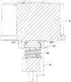
FIG. 3 isbase:Sub>A schematic partial cross-sectional view taken along line A-A of FIG. 2;
fig. 4 is a schematic view of the overall structure of the first thread ring in the unlocked state;
fig. 5 is a schematic partial cross-sectional view taken along line B-B in fig. 4.
In the figure: 1. a rod body; 11. a threaded segment; 12. a first sliding groove; 13. a second sliding groove; 2. a first thread turn; 21. a first cylinder; 211. a first thread; 22. a second ring body; 221. a first clamping through hole; 3. a second thread turn; 31. a second cylinder; 311. a second thread; 32. a fourth ring body; 4. a first locking assembly; 41. a first fixing member; 42. a first elastic member; 43. a first locking member; 431. a first ring body; 432. a first clamping block; 433. a first slider; 5. a second locking assembly; 51. a second fixing member; 52. a second elastic member; 53. a second locking member; 54. a second clamping block; 6. a stroke slip sheet; 7. and (4) stroke thread.
Detailed Description
In order to make the objects, features and advantages of the present invention more comprehensible, embodiments of the present invention are described in detail below with reference to the accompanying drawings. Several embodiments of the invention are presented in the drawings. The invention may, however, be embodied in many different forms and should not be construed as limited to the embodiments set forth herein.
In the present invention, unless otherwise explicitly specified or limited, the terms "mounted," "connected," "secured," and the like are to be construed broadly, e.g., as being fixedly connected, detachably connected, or integrally connected; can be mechanically or electrically connected; they may be connected directly or indirectly through intervening media, or they may be interconnected between two elements. The specific meaning of the above terms in the present invention can be understood according to specific situations by those skilled in the art. The terms "first", "second" and "first" are used for descriptive purposes only and are not to be construed as indicating or implying relative importance or implicitly indicating the number of technical features indicated. Thus, a feature defined as "first" or "second" may explicitly or implicitly include one or more of that feature.
The present invention will be described in detail with reference to the accompanying drawings and examples.
The utility model provides a screw rod stroke locator, as shown in figure 1, include: a rod body 1; the middle part of the rod body 1 is provided with a threaded section 11; one end of the rod body 1 is rotatably provided with a first thread ring 2 matched with the thread section 11, and the other end of the rod body is provided with a second thread ring 3 matched with the thread section 11; the rod body 1 is also provided with a first locking component 4 for locking the first thread ring 2 and a second locking component 5 for locking the second thread ring 3; the thread section 11, the first thread turn 2 and the second thread turn 3 form a stroke thread 7; a stroke sliding sheet 6 is connected to the stroke thread 7 in a threaded manner; after the stroke sliding piece 6 moves to the limit position of the first thread ring 2, the stroke sliding piece 6 extrudes the first locking component 4 to release the locking state of the first locking component 4 on the first thread ring 2; after the stroke sliding piece 6 moves to the limit position of the second thread ring 3, the stroke sliding piece 6 presses the second locking component 5 to release the locking state of the second locking component 5 on the second thread ring 3.
In practical application, when the first locking component 4 locks the first thread ring 2 and the second locking component 5 locks the second thread ring 3, the first thread ring 2 and the second thread ring 3 are both difficult to rotate with the rod body 1, the first thread ring 2 is in threaded engagement with one end of the threaded section 11, the second thread ring 3 is in threaded engagement with the other end of the threaded section 11, under the condition that the rod body 1 continuously rotates, the rod body 1 drives the first locking component 4 and the second locking component 5 to rotate, the first locking component 4 drives the first thread ring 2 to rotate, the second locking component 5 drives the second thread ring 3 to rotate, so that the stroke thread 7 rotates, the stroke slide sheet 6 slides on the stroke thread 7, and in the process that the stroke slide sheet 6 slides to the limit position of the first thread ring 2, the limiting position is the end part of the stroke thread 7, the stroke sliding sheet 6 gradually extrudes the first locking component 4, so that the connection state of the first locking component 4 and the first thread ring 2 is changed, namely the locking state of the first locking component 4 on the first thread ring 2 is released, at the moment, the first thread ring 2 is in an unlocking state, the rod body 1 continuously rotates, the rod body 1 continuously drives the first locking component 4, the second locking component 5 and the thread section 11 to rotate, but the first thread ring 2 is in the unlocking state, the first thread ring 2 does not rotate, so that the stroke sliding sheet 6 on the first thread ring 2 does not continuously slide, the limiting protection effect is achieved, the stroke sliding sheet 6 is prevented from continuously sliding to cause abrasion among parts, and the service life of a product is prolonged; when the rod body 1 rotates reversely, if the stroke sliding piece 6 slides to the limit position of the second thread ring 3, the process that the stroke sliding piece 6 extrudes the second locking component 5 to release the locking state of the second thread ring 3 is the same as the process that the stroke sliding piece 6 extrudes the first locking component 4 to release the locking state of the first thread ring 2, and details are not repeated here.
Further, as shown in fig. 2 and fig. 3, a first clamping block 432 is arranged on the first locking component 4; one end of the first clamping block 432 close to the stroke sliding sheet 6 is obliquely arranged; a first clamping through hole 221 matched with the first clamping block 432 is formed in the first thread ring 2, so that the first clamping block 432 extends out; the first clamping block 432 is clamped on the first clamping through hole 221; as shown in fig. 4 and 5, after the stroke sliding piece 6 moves to the limit position of the first thread ring 2, the stroke sliding piece 6 extrudes the first clamping block 432 to release the clamping state between the first clamping block 432 and the first clamping through hole 221.
In practical applications, when the stroke slip sheet 6 does not slide to the limit position of the first thread ring 2, the first clamping block 432 is clamped on the first clamping through hole 221, and a part of the first clamping through hole 221 extends out, when the rod body 1 drives the first locking component 4 and the first thread ring 2 to rotate, the stroke slip sheet 6 gradually slides to the limit position of the first thread ring 2, in the process, the stroke slip sheet 6 gradually approaches and extrudes the first clamping block 432, so that the first clamping block 432 moves downward, as shown in fig. 5, until the part of the first clamping block 432 extending out of the first clamping through hole 221 is completely located in the first clamping through hole 221, so that the first thread ring 2 is in an unlocking state, at this time, if the rotation direction of the rod body 1 viewed from top down is a clockwise direction, the inclination direction of the first clamping block 432 approaching the stroke slip sheet 6 is gradually inclined from right to left, and the first clamping through hole 221 is adapted to the first clamping block 432, in the case that the rod body 1 rotates clockwise, the rod body 1 drives the first clamping block 221 to gradually rotate from the first clamping through hole 221, and the first clamping block 432 does not rotate clockwise, and the first clamping through hole 432 continues to rotate, and the first clamping through hole 2, and the first clamping through hole 432 continues to rotate, and the stroke slip sheet 1 rotates to the first clamping through hole 2, so that the first clamping through hole 1 does not rotate clockwise; under the condition of the position of stroke gleitbretter 6 needs to be readjusted, control body of rod 1 antiport, that is to say, control body of rod 1 rotates according to the anticlockwise from last down looking, then body of rod 1 drives first joint piece 432 anticlockwise rotation, first joint piece 432 antiport is to first joint through-hole 221 department back, the right side wall of first joint piece 432 and the lateral wall butt of first joint through-hole 221, make first joint piece 432 antiport can drive first screw ring 2 antiport, thereby make stroke gleitbretter 6 backsliding, keep away from first locking Assembly 4 gradually, this application can play stroke limiting displacement to stroke gleitbretter 6, strengthen the guard action to stroke gleitbretter 6, and do not influence and carry out subsequent antiport to stroke gleitbretter 6 with the position of adjustment stroke gleitbretter 6.
Further, as shown in fig. 3, the first locking member 4 includes: a first fixing member 41, a first elastic member 42, and a first locking member 43; the first fixing piece 41 is arranged on the rod body 1; the first locking piece 43 is arranged on the rod body 1 in an axial sliding manner along the rod body 1; one end of the first elastic member 42 abuts against the first fixing member 41, and the other end abuts against the first locking member 43; the first catching block 432 is disposed on the first locking member 43.
Specifically, the first elastic member 42 is a spring in the present application, and in other embodiments, the first elastic member 42 may be made of an elastic material such as silicone; the first fixing member 41 is annular, and when the rod body 1 rotates clockwise so that the stroke sliding piece 6 pushes the first clamping block 432 to move downwards, the first elastic member 42 is compressed; under the condition that the rod body 1 rotates anticlockwise to enable the first clamping block 432 to be located in the first clamping through hole 221, the first clamping block 432 drives the first threaded ring 2 to rotate anticlockwise, so that the stroke sliding piece 6 gradually rises, and under the action of the elastic force of the first elastic piece 42, the first locking piece 43 also gradually rises, so that the first clamping block 432 gradually extends out of the first clamping through hole 221 to lock the first threaded ring 2; through the arrangement of the first elastic member 42, the first locking member 43 can be enabled to re-lock the first thread ring 2 when the rod body 1 is rotated reversely.
Further, as shown in fig. 1, the first locking member 43 includes: a first ring 431 and at least one first slider 433; the first sliding block 433 and the first clamping block 432 are both arranged on the first ring body 431; the first ring body 431 is sleeved on the rod body 1; at least one first sliding groove 12 corresponding to the at least one first sliding block 433 is axially formed on the rod body 1; the first sliding block 433 is slidably disposed on the first sliding groove 12.
Specifically, through the arrangement of the first sliding block 433 and the first sliding groove 12, the first locking member 43 is ensured to slide along the axial direction of the rod body 1, and the first locking member 43 is prevented from rotating with the rod body 1, so that the first locking member 43 can be driven to rotate by the rotation of the rod body 1.
Further, as shown in fig. 1 and 2, the first thread turn 2 includes: a first cylinder 21 and a second ring 22; the first cylinder 21 and the second ring 22 are fixedly connected; the first cylinder 21 and the second ring 22 are sleeved at one end of the rod body 1; the first cylinder 21 is provided with a first thread 211; the threaded section 11, the first thread 211 and the second thread turn 3 form a stroke thread 7; the first clamping through hole 221 is formed in the second ring body 22.
Specifically, through the arrangement of the first barrel 21 and the second barrel 22, the first thread ring 2 is conveniently sleeved on the rod body 1, the first thread ring 2 is in an unlocked state, so that the first thread ring 2 and the rod body 1 can rotate, and when the first clamping block 432 is located in the first clamping through hole 221, at this time, the first thread 211 is engaged with one end of the thread section 11, so that the stroke sliding piece 6 can slide from the first thread 211 to the thread section 11 or from the thread section 11 to the first thread 211.
Further, a second clamping block 54 is arranged on the second locking component 5; one end of the second clamping block 54 close to the stroke sliding piece 6 is obliquely arranged; the inclination direction of the end, close to the stroke sliding piece 6, of the second clamping block 54 is opposite to the inclination direction of the end, close to the stroke sliding piece 6, of the first clamping block 432; a second clamping through hole matched with the second clamping block 54 is formed in the second thread ring 3, so that the second clamping block 54 can extend out; the second clamping block 54 is clamped on the second clamping through hole; after the stroke slip sheet 6 moves to the limit position of the second thread ring 3, the stroke slip sheet 6 extrudes the second clamping block 54 to release the clamping state of the second clamping block 54 and the second clamping through hole.
Specifically, the first clamping block 432 is located at the bottom end of the rod body 1, the second clamping block 54 is located at the top end of the rod body 1, and since the inclination direction of one end, close to the stroke slip sheet 6, of the second clamping block 54 is opposite to the inclination direction of one end, close to the stroke slip sheet 6, of the first clamping block 432, under the condition that the rod body 1 moves counterclockwise, the stroke slip sheet 6 moves upward until the stroke slip sheet 6 pushes all the part, extending out of the second clamping through hole, of the second clamping block 54 into the second clamping through hole, the rod body 1 continues to move counterclockwise, so that the rod body 1 drives the second clamping block 54 to rotate to completely slide out of the second clamping through hole, the locking state of the second thread ring 3 is released, the second thread ring 3 does not rotate, and the stroke slip sheet 6 does not continue to slide upward; when the position of stroke gleitbretter 6 needs to be adjusted, clockwise turning the body of rod 1 for second joint piece 54 is located the second joint through-hole, as shown in fig. 1, the right side wall and the second joint through-hole butt of second joint piece 54 make second joint piece 54 drive second thread circle 3 clockwise turning, thereby make stroke gleitbretter 6 lapse.
Further, as shown in fig. 1, the second locking assembly 5 includes: a second fixed member 51, a second elastic member 52, and a second locking member 53; the second fixing piece 51 is arranged on the rod body 1; the second locking piece 53 is arranged on the rod body 1 in an axial sliding manner along the rod body 1; one end of the second elastic member 52 abuts against the second fixing member 51, and the other end abuts against the second locking member 53; the second locking piece 54 is disposed on the second locking member 53.
Specifically, the second elastic member 52 is a spring in the present application, and in other embodiments, the second elastic member 52 may be made of an elastic material such as silicone; the second fixed part 51 is annular, and the second elastic part 52 is compressed when the rod body 1 rotates anticlockwise to enable the stroke sliding piece 6 to push the second clamping block 54 to move upwards; under the condition that the rod body 1 rotates clockwise to enable the second clamping block 54 to be located in the second clamping through hole, the second clamping block 54 drives the second threaded ring 3 to rotate clockwise, so that the stroke sliding sheet 6 gradually descends, and under the action of the elastic force of the second elastic piece 52, the second locking piece 53 also gradually descends, so that the second clamping block 54 gradually extends out of the second clamping through hole to lock the second threaded ring 3; by the arrangement of the second elastic member 52, when the rod body 1 is rotated clockwise, the second locking member 53 can be enabled to lock the second thread ring 3 again.
Further, the second locking piece 53 includes: the third ring body and at least one second sliding block; the second sliding block and the second clamping block 54 are both arranged on the third ring body; the third ring body is sleeved on the rod body 1; at least one second sliding groove 13 corresponding to the at least one second sliding block is axially formed in the rod body 1; the second slide block is slidably disposed on the second slide groove 13.
Specifically, the inclination direction of the end of the second clamping block 54 close to the stroke slide 6 is opposite to the inclination direction of the end of the first clamping block 432 close to the stroke slide 6, that is, when the first locking member 43 and the second locking member 53 are oppositely arranged, the inclination direction of the end of the first clamping block 432 close to the stroke slide 6 is gradually close to the first ring body 431 from left to right, and the inclination direction of the end of the second clamping block 54 close to the stroke slide 6 is gradually close to the third ring body from right to left; through the setting of second sliding block and second sliding tray 13, ensured that second locking piece 53 along the axial slip of the body of rod 1, prevented to produce between second locking piece 53 and the body of rod 1 and rotated to it can drive second locking piece 53 and rotate to have ensured that body of rod 1 rotates.
Further, the second thread turn 3 includes: a second cylinder 31 and a fourth cylinder 32; the second cylinder 31 is fixedly connected with the fourth cylinder 32; the second cylinder 31 and the fourth ring body 32 are sleeved at the other end of the rod body 1; the second cylinder 31 is provided with a second thread 311; the threaded section 11, the first thread 211 and the second thread 311 form a travel thread 7; the second clamping through hole is formed in the fourth ring 32.
Specifically, through the setting of second barrel 31 and fourth ring 32, be convenient for second thread circle 3 cover is established on the body of rod 1, be in the condition of unblock state at second thread circle 3 for can take place between second thread circle 3 and the body of rod 1 and rotate, be located the condition of second joint through-hole at second joint piece 54, this moment, the other end joint of second screw thread 311 and screw thread section 11 makes stroke gleitbretter 6 can slide to screw thread section 11 or slide to second screw thread 311 from screw thread section 11 from second screw thread 311.
The utility model discloses a screw rod stroke locator, through the cooperation of first locking Assembly 4 and first fillet of screw 2, second locking Assembly 5 and the cooperation of second fillet of screw 3 to play spacing guard action to stroke gleitbretter 6, thereby prevented that stroke gleitbretter 6 from continuing to slide to both ends and cause the wearing and tearing between the part, improved the life of product.
It is above only the utility model discloses a preferred embodiment, the utility model discloses a scope of protection does not only confine above-mentioned embodiment, the all belongs to the utility model discloses a technical scheme under the thinking all belongs to the utility model discloses a scope of protection. It should be noted that, for those skilled in the art, various modifications and decorations can be made without departing from the principle of the present invention, and these modifications and decorations should also be regarded as the protection scope of the present invention.
Claims (9)
1. A screw stroke locator, comprising: a rod body; the middle part of the rod body is provided with a thread section; one end of the rod body is rotatably provided with a first thread ring matched with the thread section, and the other end of the rod body is provided with a second thread ring matched with the thread section; the rod body is also provided with a first locking component for locking the first thread ring and a second locking component for locking the second thread ring; the thread section, the first thread turn and the second thread turn form a stroke thread; a stroke sliding sheet is connected to the stroke thread in a threaded manner; after the stroke sliding sheet moves to the limit position of the first thread ring, the stroke sliding sheet extrudes the first locking component to release the locking state of the first locking component on the first thread ring; after the stroke sliding sheet moves to the limiting position of the second thread ring, the stroke sliding sheet extrudes the second locking assembly to release the locking state of the second locking assembly on the second thread ring.
2. The screw stroke locator of claim 1, wherein the first locking component is provided with a first snap-in block; one end of the first clamping block, which is close to the stroke sliding piece, is obliquely arranged; a first clamping through hole matched with the first clamping block is formed in the first threaded ring, so that the first clamping block can extend out; the first clamping block is clamped on the first clamping through hole; after the stroke slip sheet moves to the limiting position of the first thread ring, the stroke slip sheet extrudes the first clamping block to release the clamping state of the first clamping block and the first clamping through hole.
3. The screw stroke locator of claim 2, wherein the first locking assembly comprises: the first fixing part, the first elastic part and the first locking part; the first fixing piece is arranged on the rod body; the first locking piece is arranged on the rod body in a sliding mode along the axial direction of the rod body; one end of the first elastic piece is abutted against the first fixing piece, and the other end of the first elastic piece is abutted against the first locking piece; the first clamping block is arranged on the first locking piece.
4. The screw stroke locator of claim 3, wherein the first locking member comprises: the first ring body and at least one first sliding block; the first sliding block and the first clamping block are arranged on the first ring body; the first ring body is sleeved on the rod body; at least one first sliding groove corresponding to the at least one first sliding block is axially formed in the rod body; the first sliding block is arranged on the first sliding groove in a sliding mode.
5. The screw stroke locator of claim 2 wherein the first thread turn comprises: a first cylinder and a second ring; the first cylinder body is fixedly connected with the second ring body; the first cylinder and the second ring body are sleeved at one end of the rod body; the first cylinder is provided with a first thread; the thread section, the first thread and the second thread turn form a stroke thread; the first clamping through hole is formed in the second ring body.
6. The screw stroke locator of any one of claims 2 to 5, wherein a second snap-in block is provided on the second locking assembly; one end of the second clamping block, which is close to the stroke sliding sheet, is obliquely arranged; the inclination direction of one end, close to the stroke sliding piece, of the second clamping block is opposite to the inclination direction of one end, close to the stroke sliding piece, of the first clamping block; a second clamping through hole matched with the second clamping block is formed in the second threaded ring, so that the second clamping block can extend out; the second clamping block is clamped on the second clamping through hole; after the stroke slip sheet moves to the limiting position of the second threaded ring, the stroke slip sheet extrudes the second clamping block to release the clamping state of the second clamping block and the second clamping through hole.
7. The screw stroke locator of claim 6, wherein the second locking assembly comprises: the second fixing piece, the second elastic piece and the second locking piece; the second fixing piece is arranged on the rod body; the second locking piece is arranged on the rod body in a sliding manner along the axial direction of the rod body; one end of the second elastic piece is abutted with the second fixing piece, and the other end of the second elastic piece is abutted with the second locking piece; the second clamping block is arranged on the second locking piece.
8. The screw stroke locator of claim 7, wherein the second lock comprises: the third ring body and at least one second sliding block; the second sliding block and the second clamping block are arranged on the third ring body; the third ring body is sleeved on the rod body; the rod body is axially provided with at least one second sliding groove corresponding to at least one second sliding block; the second sliding block is arranged on the second sliding groove in a sliding mode.
9. The screw stroke locator of claim 6, wherein the second thread turn comprises: a second cylinder and a fourth ring; the second cylinder body is fixedly connected with the fourth cylinder body; the second cylinder and the fourth cylinder are sleeved at the other end of the rod body; a second thread is arranged on the second cylinder; the thread section, the first thread turn and the second thread form a stroke thread; the second clamping through hole is formed in the fourth ring body.
Priority Applications (1)
| Application Number | Priority Date | Filing Date | Title |
|---|---|---|---|
| CN202221933529.5U CN217736188U (en) | 2022-07-25 | 2022-07-25 | Screw stroke positioner |
Applications Claiming Priority (1)
| Application Number | Priority Date | Filing Date | Title |
|---|---|---|---|
| CN202221933529.5U CN217736188U (en) | 2022-07-25 | 2022-07-25 | Screw stroke positioner |
Publications (1)
| Publication Number | Publication Date |
|---|---|
| CN217736188U true CN217736188U (en) | 2022-11-04 |
Family
ID=83849659
Family Applications (1)
| Application Number | Title | Priority Date | Filing Date |
|---|---|---|---|
| CN202221933529.5U Active CN217736188U (en) | 2022-07-25 | 2022-07-25 | Screw stroke positioner |
Country Status (1)
| Country | Link |
|---|---|
| CN (1) | CN217736188U (en) |
-
2022
- 2022-07-25 CN CN202221933529.5U patent/CN217736188U/en active Active
Similar Documents
| Publication | Publication Date | Title |
|---|---|---|
| US20150122059A1 (en) | Radially engaging system | |
| US5782118A (en) | Lockset with motorized system for locking and unlocking | |
| US9431868B2 (en) | Manual override device for an electric actuator and method for use | |
| CN1133022A (en) | Cam and wedge-type self-locking mechanism | |
| DE102016222506A1 (en) | Tool changing device | |
| CN217736188U (en) | Screw stroke positioner | |
| US9200474B1 (en) | Locking device | |
| DE112015005431T5 (en) | Extendable / shortenable drive device and openable body opening / closing device | |
| CN115095637A (en) | Screw stroke positioner | |
| CN211693213U (en) | Stand wear and tear round pin axle construction | |
| CN108571292B (en) | A kind of coiled tubing connector and application | |
| CN114197022B (en) | Tool clamp for pin shaft electroplating processing | |
| CN210512856U (en) | Quick release mechanism for gun lamp and quick release gun lamp | |
| CN218594123U (en) | Locking mechanism of new forms of energy rechargeable vehicle battery | |
| CN115592434B (en) | Positioning and supporting device for machining thin-wall shell parts | |
| WO2022142957A1 (en) | Transmission assembly and three-dimensional printing device | |
| CN111379780A (en) | Quick locking mechanism | |
| CN209837960U (en) | Handle and square shaft locking device | |
| US11525497B2 (en) | Linear actuating member driven by a rotating helix | |
| CN211229841U (en) | Back locking knob assembly and door lock | |
| CN110939329B (en) | Motor lock | |
| CN210659573U (en) | Mechanical hoist lock | |
| CN109944517B (en) | Gear interlocking type automobile back door hinge | |
| DE60201438T2 (en) | LINEAR ACTUATOR, ESPECIALLY AKTUATOR FOR PLANE BRAKES | |
| US20150267480A1 (en) | Ratchet assembly |
Legal Events
| Date | Code | Title | Description |
|---|---|---|---|
| GR01 | Patent grant | ||
| GR01 | Patent grant |