CN217709772U - Embossing machine for producing curtain cloth - Google Patents
Embossing machine for producing curtain cloth Download PDFInfo
- Publication number
- CN217709772U CN217709772U CN202221895233.9U CN202221895233U CN217709772U CN 217709772 U CN217709772 U CN 217709772U CN 202221895233 U CN202221895233 U CN 202221895233U CN 217709772 U CN217709772 U CN 217709772U
- Authority
- CN
- China
- Prior art keywords
- wall
- plate
- machine body
- motor
- motors
- Prior art date
- Legal status (The legal status is an assumption and is not a legal conclusion. Google has not performed a legal analysis and makes no representation as to the accuracy of the status listed.)
- Active
Links
Images

Abstract
The utility model discloses an gin of casement production usefulness, including organism, backup pad and telescopic link, the block is installed to the outer wall of backup pad, the touch panel is installed to the bottom of spring, the connecting rod is installed at the top of touch panel, the top of connecting rod is installed and is beaten the board, a motor is installed to the outer wall of organism, the output of a motor is installed and is changeed the board, the collecting box is installed to the inside diapire of organism. The utility model discloses an install the block, strike board and touch panel, its cotton fiber is through the block top, it is rotatory that the motor rotation drives the commentaries on classics board, its oval-shaped commentaries on classics board rotation drives the touch panel and is the up-and-down motion, the touch panel removes and drives the connecting rod and remove, thereby the connecting rod removes to make to strike the board vibration from top to bottom and is beating the block, make remaining cottonseed between the cotton fiber receive the vibration to drop in the collecting box of bottom side, this structure has improved the separation effect of cottonseed, make the cottonseed remain few, improved the processing effect.
Description
Technical Field
The utility model relates to an embossing equipment technical field specifically is an embossing machine of casement production usefulness.
Background
The production raw material of the curtain cloth is mainly cotton, cotton seeds need to be taken out in the cotton processing process, cotton ginning machines are one of cotton processing machines of cotton ginning machines, lint cotton is separated from cotton seeds, the quality and the cotton seeds of cotton fibers are required not to be damaged in the ginning process, two types of common saw-tooth ginning machines and roller ginning machines are used, cotton fibers are attached and driven by the surface of a leather roller with a large friction coefficient, and therefore the purpose of separating the cotton fibers from the cotton seeds is achieved.
The existing cotton gin has the following defects:
patent document CN216274471U discloses a cotton gin for textile use, which comprises a feeding port, a heat dryer, a communicating pipe, a roller cage, a first roller, a pressing rib, a second roller, a pushing roller, a rubber sleeve, a driven belt pulley, an electric cabinet, a driving belt pulley, a first belt, a second belt, a driving motor and a driving belt pulley. Through the outer wall surface with the inner wall fixed connection propelling movement roller of rubber sleeve, rotate the inner wall surface of connecting the pressure cotton storehouse through the bull stick with the wall of propelling movement roller, carry the cotton to the outside of box when the propelling movement roller rotates, rotate the inner wall surface of connecting the pressure cotton storehouse through the bull stick with the wall of first roller and second roller, roll the inside cotton in pressure cotton storehouse when first roller and second roller rotate, through the outer wall surface of the first roller of tip fixed connection with the pressure muscle, roll the cotton through the pressure muscle, be convenient for fold the cotton after rolling and accomodate.
The cotton gin disclosed in the above publication mainly solves the problem that rolled cotton is folded and stored, and does not solve the problem that the cotton seeds cannot be taken out cleanly by the existing cotton gin.
In view of the above, there is a need to develop an embossing machine for producing a curtain fabric, so as to solve the problem of thorough cotton seed removal of the embossing machine and improve the processing effect.
SUMMERY OF THE UTILITY MODEL
An object of the utility model is to provide an embossing machine of casement production usefulness to solve the problem of the lubricated structure of connecting and pipe length adjustment that provides among the above-mentioned background art.
In order to achieve the above object, the utility model provides a following technical scheme: the cotton gin for producing the curtain cloth comprises a machine body, a supporting plate and a telescopic rod, wherein the supporting plate is arranged on the inner wall of the machine body;
the device comprises a supporting plate, a connecting rod, a beating plate, a first motor, a rotating plate and a collecting box, wherein a blocking net is arranged on the outer wall of the supporting plate, a fixed plate is arranged on the inner wall of the machine body, a spring is arranged at the bottom of the fixed plate, a touch plate is arranged at the bottom of the spring, the connecting rod is arranged at the top of the touch plate, the beating plate is arranged at the top of the connecting rod, the first motor is arranged on the outer wall of the machine body, the rotating plate is arranged at the output end of the first motor, and the collecting box is arranged on the inner bottom wall of the machine body;
the telescopic rod is installed on the inside roof of organism.
Preferably, the top of organism is installed the feed inlet, and the supporting legs is installed to the bottom of organism, and the controller is installed to the outer wall of organism.
Preferably, the bottom of the telescopic rod is provided with a connecting plate, and the bottom of the connecting plate is provided with a supporting block.
Preferably, the outer wall of the supporting block is provided with a second motor, the output end of the second motor is provided with a driving wheel, and the outer wall of the driving wheel is provided with a conveying belt.
Preferably, no. three motors are installed to the inside roof of organism, and the threaded rod is installed to the output of No. three motors, and the one end of threaded rod extends into the inside of connecting plate.
Preferably, the outer wall of the machine body is provided with a fourth motor, and the output end of the fourth motor is provided with the embossing roller.
Preferably, the outer wall of the machine body is provided with a fifth motor, and the output end of the fifth motor is provided with a rotating wheel.
Compared with the prior art, the beneficial effects of the utility model are that:
1. the utility model discloses an install block, strike board and touch panel, its cotton fiber is through the block top, the rotatory commentaries on classics board rotation that drives of a motor, its spring is with touch panel's outer wall laminating all the time, its oval-shaped commentaries on classics board rotation drives touch panel and does the up-and-down motion, touch panel removes and drives the connecting rod and removes, thereby the connecting rod removes and makes to strike the board vibration from top to bottom and strike the block, make the residual cottonseed between the cotton fiber drop in the collecting box of bottom side by the vibration, this structure has improved the separation effect of cottonseed, make the cottonseed remain few, has improved the processing effect;
2. the utility model discloses an install the conveyer belt, threaded rod and connecting plate, the cotton fiber contact that its conveyer belt and processing finished, make cotton fiber be carried by the bottom side of rotatory conveyer belt direction to conveyer belt, and loose cotton fiber is by the conveyer belt and the backup pad centre gripping of removal, make cotton fiber carry out the ejection of compact with suitable slice or cubic, and when needing to change ejection of compact thickness, no. three motor rotations drive the threaded rod rotatory, the threaded rod is rotatory to drive the connecting plate and is removed, the connecting plate removes and drives the carriage removal, the carriage removal is adjusted the position of conveyer belt, make the interval of conveyer belt and backup pad also can be adjusted, thereby make ejection of compact thickness change, this structure can be as required, make loose cotton fiber become the slice ejection of compact of suitable thickness, subsequent processing has been made things convenient for.
Drawings
Fig. 1 is a schematic view of the overall structure of the present invention;
fig. 2 is a schematic front structural view of the present invention;
fig. 3 is a schematic view of the structure of the barrier of the present invention;
fig. 4 is a schematic diagram of the structure of the conveyor belt of the present invention.
In the figure: 1. a body; 101. a feed inlet; 102. supporting legs; 103. a controller; 2. a support plate; 201. blocking a net; 202. a fixing plate; 203. a spring; 204. a touch panel; 205. a connecting rod; 206. knocking a plate; 207. a first motor; 208. rotating the plate; 209. a collection box; 3. a telescopic rod; 301. a connecting plate; 302. a supporting block; 4. a second motor; 401. a driving wheel; 402. a conveyor belt; 5. a third motor; 501. a threaded rod; 6. a fourth motor; 601. embossing rollers; 7. a fifth motor; 701. a rotating wheel.
Detailed Description
The technical solutions in the embodiments of the present invention will be described clearly and completely with reference to the drawings in the embodiments of the present invention, and it is obvious that the described embodiments are only some embodiments of the present invention, not all embodiments. Based on the embodiments in the present invention, all other embodiments obtained by a person skilled in the art without creative work belong to the protection scope of the present invention.
In the description of the present invention, it should be noted that the terms "upper", "lower", "inner", "outer", "front", "rear", "both ends", "one end", "the other end", and the like indicate orientations or positional relationships based on the orientations or positional relationships shown in the drawings, and are only for convenience of description and simplification of the description, but do not indicate or imply that the device or element referred to must have a specific orientation, be constructed and operated in a specific orientation, and thus, should not be construed as limiting the present invention. Furthermore, the terms "first" and "second" are used for descriptive purposes only and are not to be construed as indicating or implying relative importance.
In the description of the present invention, it should be noted that, unless otherwise explicitly specified or limited, the terms "mounted," "provided," "connected," and the like are to be construed broadly, such as "connected," which may be fixedly connected, detachably connected, or integrally connected; can be mechanically or electrically connected; they may be connected directly or indirectly through intervening media, or they may be interconnected between two elements. The specific meaning of the above terms in the present invention can be understood as a specific case by those skilled in the art.
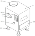
Referring to fig. 1 and 2, an embossing machine for producing a curtain fabric includes a machine body 1, a support plate 2 and an expansion link 3, a feed inlet 101 is installed at the top of the machine body 1, a support leg 102 is installed at the bottom of the machine body 1, a controller 103 is installed on the outer wall of the machine body 1, a fourth motor 6 is installed on the outer wall of the machine body 1, an embossing roller 601 is installed at the output end of the fourth motor 6, a fifth motor 7 is installed on the outer wall of the machine body 1, a rotating wheel 701 is installed at the output end of the fifth motor 7, raw materials are fed from the feed inlet 101, the fourth motor 6 rotates to drive the embossing roller 601 to rotate, the fifth motor 7 rotates to drive the rotating wheel 701 to rotate, and the rotating roller 701 and the embossing roller 601 separate cotton fibers from cotton seeds, thereby completing processing.
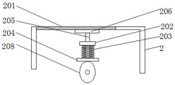
Referring to fig. 2 and 3, the inner wall of the machine body 1 is provided with the support plate 2, the outer wall of the support plate 2 is provided with the barrier net 201, the inner wall of the machine body 1 is provided with the fixed plate 202, the bottom of the fixed plate 202 is provided with the spring 203, the bottom of the spring 203 is provided with the contact plate 204, the top of the contact plate 204 is provided with the connecting rod 205, the top of the connecting rod 205 is provided with the beating plate 206, the outer wall of the machine body 1 is provided with the first motor 207, the output end of the first motor 207 is provided with the rotating plate 208, the inner bottom wall of the machine body 1 is provided with the collecting box 209, the cotton fibers pass through the top of the barrier net 201, the first motor 207 rotates to drive the rotating plate 208 to rotate, the spring 203 enables the contact plate 204 to be always attached to the outer wall of the rotating plate 208, the elliptical rotating plate 208 rotates to drive the contact plate 204 to move up and down, the contact plate 204 moves to drive the connecting rod 205 to move, the connecting rod 205 moves to enable the beating plate 206 to vibrate up and beat the barrier net 201 up and down, so that residual cotton seeds among the cotton fibers fall into the collecting box 209 at the bottom side.
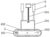
Referring to fig. 2 and 4, an expansion link 3 is installed on the inner top wall of the machine body 1, a connecting plate 301 is installed at the bottom of the expansion link 3, a supporting block 302 is installed at the bottom of the connecting plate 301, a second motor 4 is installed on the outer wall of the supporting block 302, a driving wheel 401 is installed at the output end of the second motor 4, a conveying belt 402 is installed on the outer wall of the driving wheel 401, a third motor 5 is installed on the inner top wall of the machine body 1, a threaded rod 501 is installed at the output end of the third motor 5, one end of the threaded rod 501 extends into the connecting plate 301, the conveying belt 402 contacts with processed cotton fibers, the cotton fibers are guided to the bottom side of the conveying belt 402 by the rotating conveying belt 402 and conveyed, loose cotton fibers are clamped by the moving conveying belt 402 and the supporting plate 2, the cotton fibers are discharged in a proper sheet shape or block shape, when the discharging thickness needs to be changed, the third motor 5 rotates to drive the connecting plate 501 to move, the connecting plate 301 is moved by the connecting plate 301, the supporting plate 301 moves to drive the supporting plate 2 to move, the position of the supporting plate 402 to adjust the distance between the conveying belt 402 and the supporting plate 2 to adjust the discharging thickness, thereby changing the discharging thickness of the loose cotton fibers as required, and facilitating the subsequent processing of the subsequent sheet shape.
The working principle is that raw materials are added from a feeding hole 101, a motor 6 rotates to drive a cotton roller 601 to rotate, a motor 7 rotates to drive a rotating wheel 701 to rotate, the rotating roller 701 and the cotton roller 601 separate cotton fibers from cotton seeds, processing is completed, the cotton fibers pass through the top of a blocking net 201, a motor 207 rotates to drive a rotating plate 208 to rotate, a spring 203 of the motor attaches a contact plate 204 to the outer wall of the rotating plate 208 all the time, the elliptical rotating plate 208 rotates to drive the contact plate 204 to move up and down, the contact plate 204 moves to drive a connecting rod 205 to move, the connecting rod 205 moves to enable a beating plate 206 to vibrate up and down to beat the blocking net 201, residual cotton seeds between the cotton fibers fall into a collecting box 209 at the bottom side under vibration, the structure improves the separation effect of the cotton seeds, the cotton seeds are less left, the processing effect is improved, the conveying belt 402 is in contact with the processed cotton fibers, the cotton fibers are guided to the bottom side of the conveying belt 402 by the rotating conveying belt 402 to be conveyed, the loose cotton fibers are clamped between the conveying belt 402 and the supporting plate 2, the cotton fibers are enabled to be conveyed, the supporting plate 402 to be driven by the rotating belt 402, the supporting plate 402 to move to adjust the thickness of the supporting plate 301, and the supporting plate 501, and the supporting plate, the supporting plate 501, and the supporting plate can be adjusted according to adjust the thickness of the supporting plate, and the supporting plate 501, and the supporting plate.
It is obvious to a person skilled in the art that the invention is not restricted to details of the above-described exemplary embodiments, but that it can be implemented in other specific forms without departing from the spirit or essential characteristics of the invention. The present embodiments are therefore to be considered in all respects as illustrative and not restrictive, the scope of the invention being indicated by the appended claims rather than by the foregoing description, and all changes which come within the meaning and range of equivalency of the claims are therefore intended to be embraced therein. Any reference sign in a claim should not be construed as limiting the claim concerned.
Claims (7)
1. The utility model provides an gin of casement production usefulness, includes organism (1), backup pad (2) and telescopic link (3), its characterized in that: a support plate (2) is arranged on the inner wall of the machine body (1);
a blocking net (201) is installed on the outer wall of the supporting plate (2), a fixing plate (202) is installed on the inner wall of the machine body (1), a spring (203) is installed at the bottom of the fixing plate (202), a contact plate (204) is installed at the bottom of the spring (203), a connecting rod (205) is installed at the top of the contact plate (204), a striking plate (206) is installed at the top of the connecting rod (205), a first motor (207) is installed on the outer wall of the machine body (1), a rotating plate (208) is installed at the output end of the first motor (207), and a collecting box (209) is installed on the inner bottom wall of the machine body (1);
the top wall in the machine body (1) is provided with a telescopic rod (3).
2. The embossing machine for producing curtain cloth according to claim 1, wherein: a feeding hole (101) is installed at the top of the machine body (1), supporting legs (102) are installed at the bottom of the machine body (1), and a controller (103) is installed on the outer wall of the machine body (1).
3. The embossing machine for producing curtain cloth according to claim 1, wherein: connecting plate (301) is installed to the bottom of telescopic link (3), and supporting shoe (302) are installed to the bottom of connecting plate (301).
4. The embossing machine for producing curtain cloth according to claim 3, wherein: no. two motors (4) are installed to the outer wall of supporting shoe (302), drive wheel (401) are installed to the output of No. two motors (4), and conveyer belt (402) are installed to the outer wall of drive wheel (401).
5. The embossing machine for producing curtain cloth according to claim 1, wherein: no. three motors (5) are installed to the inside roof of organism (1), and threaded rod (501) are installed to the output of No. three motors (5), and the one end of threaded rod (501) extends into the inside of connecting plate (301).
6. The embossing machine for producing curtain cloth according to claim 1, wherein: no. four motors (6) are installed on the outer wall of the machine body (1), and the embossing rollers (601) are installed at the output ends of the No. four motors (6).
7. The embossing machine for producing curtain cloth according to claim 1, wherein: no. five motors (7) are installed to the outer wall of organism (1), and swiveling wheel (701) is installed to the output of No. five motors (7).
Priority Applications (1)
| Application Number | Priority Date | Filing Date | Title |
|---|---|---|---|
| CN202221895233.9U CN217709772U (en) | 2022-07-22 | 2022-07-22 | Embossing machine for producing curtain cloth |
Applications Claiming Priority (1)
| Application Number | Priority Date | Filing Date | Title |
|---|---|---|---|
| CN202221895233.9U CN217709772U (en) | 2022-07-22 | 2022-07-22 | Embossing machine for producing curtain cloth |
Publications (1)
| Publication Number | Publication Date |
|---|---|
| CN217709772U true CN217709772U (en) | 2022-11-01 |
Family
ID=83779474
Family Applications (1)
| Application Number | Title | Priority Date | Filing Date |
|---|---|---|---|
| CN202221895233.9U Active CN217709772U (en) | 2022-07-22 | 2022-07-22 | Embossing machine for producing curtain cloth |
Country Status (1)
| Country | Link |
|---|---|
| CN (1) | CN217709772U (en) |
-
2022
- 2022-07-22 CN CN202221895233.9U patent/CN217709772U/en active Active
Similar Documents
| Publication | Publication Date | Title |
|---|---|---|
| CN109736065B (en) | Device is tailor to cloth for textile production | |
| CN110552098B (en) | Surface treatment system for production and processing of regenerated textile cotton yarns | |
| CN108532034B (en) | Flax carding and conveying mechanism | |
| CN212669883U (en) | Pretreatment production line for preparing functional polyester blended yarn | |
| CN111847058A (en) | Wrap-up equipment for warp knitting surface fabric | |
| CN110592748A (en) | Wool spinning production device with dust removal function | |
| CN217709772U (en) | Embossing machine for producing curtain cloth | |
| CN116136045B (en) | Automatic unhairing equipment for fiber textile fabric | |
| CN216404608U (en) | Opening device of cashmere raw materials | |
| CN109252257A (en) | A kind of clear comb equipment of weaving | |
| CN213568734U (en) | Tension adjusting mechanism of warp knitting machine | |
| CN213507726U (en) | Textile product cleaning device | |
| CN211171109U (en) | Multifunctional flat knitting machine | |
| CN112553858A (en) | Batting clearing device for textile machinery with direction function | |
| CN218621181U (en) | Efficient cotton web carding device | |
| CN220394092U (en) | Elasticizing equipment for sleeping bag fabric | |
| CN214831379U (en) | Dust collector is used in surface fabric processing | |
| CN219342538U (en) | Textile fabric wetting device for spinning | |
| CN219363898U (en) | Leftover bits opener | |
| CN214830934U (en) | Stretching device is used in cotton yarn production | |
| CN217459783U (en) | Weft yarn cutting device of warp knitting machine for spinning | |
| CN219603951U (en) | Fabric steaming and ironing shaping device | |
| CN220555729U (en) | Impurity removal carding machine device for cotton yarn processing | |
| CN211056321U (en) | Fabric guiding device for computerized loom | |
| CN219990650U (en) | Non-woven fabric winding device |
Legal Events
| Date | Code | Title | Description |
|---|---|---|---|
| GR01 | Patent grant | ||
| GR01 | Patent grant |