CN217668367U - Polishing device for aluminum curtain wall plate - Google Patents
Polishing device for aluminum curtain wall plate Download PDFInfo
- Publication number
- CN217668367U CN217668367U CN202221592899.7U CN202221592899U CN217668367U CN 217668367 U CN217668367 U CN 217668367U CN 202221592899 U CN202221592899 U CN 202221592899U CN 217668367 U CN217668367 U CN 217668367U
- Authority
- CN
- China
- Prior art keywords
- threaded rod
- bevel gear
- lead screw
- drives
- fixedly connected
- Prior art date
- Legal status (The legal status is an assumption and is not a legal conclusion. Google has not performed a legal analysis and makes no representation as to the accuracy of the status listed.)
- Active
Links
Images


Landscapes
- Finish Polishing, Edge Sharpening, And Grinding By Specific Grinding Devices (AREA)
Abstract
The utility model discloses a processingequipment that polishes of aluminium curtain wallboard, including the control box, the inside of control box is equipped with intermittent type mechanism, intermittent type mechanism includes motor, first bevel gear group, runner, sheave, second bevel gear group, reciprocal lead screw, screw nut and second spout. This aluminium curtain wallboard's processingequipment that polishes, by a motor, first bevel gear group, the runner, the sheave, second bevel gear group, reciprocal lead screw, the cooperation between screw nut and the second spout, the round pin axle drives the runner and rotates, the runner drives sheave intermittent type rotation, the sheave drives the round pin axle and rotates, the round pin axle drives second bevel gear group and rotates, second bevel gear group drives reciprocal lead screw and rotates, reciprocal lead screw drives screw nut and slides in the second spout, realized when polishing for aluminium curtain wallboard, polisher and aluminium curtain wallboard synchronous motion, the condition that repeated polishing can appear when polishing has been solved, reduce work efficiency's problem.
Description
Technical Field
The utility model relates to an aluminium curtain board technical field specifically is an aluminium curtain board's processingequipment that polishes.
Background
The aluminum curtain wall plate adopts high-quality high strength aluminum alloy plate, and its structure mainly comprises pre-buried board, panel, strengthening rib and angle sign indicating number, and the pre-buried board passes through bolt and structural connection atress, and the angle sign indicating number can be directly bent, stamping forming by the panel, also can rivet the angle sign indicating number shaping on the little edge of panel, and the strengthening rib becomes a firm whole with the electric welding screw connection behind the face.
When current aluminium curtain wallboard's processingequipment that polishes is polished for aluminium curtain wallboard, polisher lateral shifting is polished, after lateral shifting finishes polishing, need longitudinal movement aluminium curtain wallboard partly, aluminium curtain wallboard longitudinal shifting during with polisher lateral shifting asynchronous, the condition that can appear repeatedly polishing when having to polish, reduce work efficiency's problem, when fixed aluminium curtain wallboard, can not fix according to the aluminium curtain wallboard of different width, there is the fixed range relatively to be restricted, can not process the problem of different width aluminium curtain wallboards.
SUMMERY OF THE UTILITY MODEL
An object of the utility model is to provide a processingequipment that polishes of aluminum curtain wallboard, with the processingequipment that polishes of the aluminum curtain wallboard that provides in solving above-mentioned background art when polishing for aluminum curtain wallboard, polisher lateral shifting polishes, after the lateral part finishes polishing, need longitudinal movement aluminum curtain wallboard partly, it is asynchronous when polishing with polisher lateral shifting during aluminum curtain wallboard longitudinal shifting, the condition of repeated polishing can appear when having to polish, reduce work efficiency's problem, when fixed aluminum curtain wallboard, can not fix according to the aluminum curtain wallboard of different width, there is the fixed range comparison and is restricted, can not process the problem of different width aluminum curtain wallboards.
In order to achieve the above object, the utility model provides a following technical scheme: a polishing device for an aluminum curtain wall plate comprises an operation box, wherein an intermittent mechanism is arranged inside the operation box;
the intermittent mechanism comprises a motor, a first bevel gear set, a rotating wheel, a grooved wheel, a second bevel gear set, a reciprocating screw rod, a screw rod nut and a second chute;
the motor passes through the motor cabinet rigid coupling on the outer wall of control box, the output shaft of motor passes through the bearing and rotates with the control box to be connected, and the output shaft rigid coupling of motor is in the one end of first bevel gear group, the other end rigid coupling of first bevel gear group is on the outer wall of round pin axle, the rigid coupling has the runner on the outer wall of round pin axle, runner and sheave are laminated mutually, the sheave rigid coupling is on the outer wall of another round pin axle, another the rigid coupling has the one end of second bevel gear group on the outer wall of round pin axle, the other end rigid coupling of second bevel gear group is on reciprocating lead screw's outer wall, two the round pin axle all rotates with the spliced pole to be connected, two the equal rigid coupling of spliced pole is in the inside of control box, reciprocating lead screw's both ends all rotate with the control box through the bearing and are connected, reciprocating lead screw and lead screw nut threaded connection, lead screw nut and second spout sliding connection, the second spout rigid coupling is in the inside of control box.
Preferably, the top of the screw nut is fixedly connected with a workbench, a groove is formed in the operation box, and the workbench is connected with the groove in a sliding mode.
Preferably, the surface of the operating box is fixedly connected with a support frame, a first sliding groove is formed in the support frame, and the first sliding groove is connected with the sliding block in a sliding mode.
Preferably, the bottom rigid coupling of slider has the hydraulic stem, the polisher is installed to the bottom of hydraulic stem.
Preferably, install electric telescopic handle on the outer wall of hydraulic stem, electric telescopic handle passes through the supporting seat rigid coupling on the outer wall of support frame.
Preferably, a fixing mechanism is arranged inside the workbench;
the fixing mechanism comprises a handle, a first threaded rod, a second threaded rod, an upright post, a transverse plate, a sliding post and a sliding rail;
first threaded rod and second threaded rod rigid coupling are connected, the tip of first threaded rod and second threaded rod is passed through the bearing and is rotated with the workstation and be connected, the handle is installed to the tip of first threaded rod, first threaded rod and second threaded rod all with stand threaded connection, two the inside processing of stand has the internal thread, two the stand all with diaphragm sliding connection, two stand and two diaphragms all with bolt threaded connection, the bottom of bolt is passed through the bearing and is rotated with the stand and be connected, two the equal rigid coupling of outer wall of stand has the traveller, two the traveller all with slide rail sliding connection, the inside at the workstation is seted up to the slide rail.
Compared with the prior art, the beneficial effects of the utility model are that: this processingequipment that polishes of aluminium curtain wall board, through the motor, first bevel gear group, the runner, the sheave, second bevel gear group, reciprocal lead screw, cooperation between screw-nut and the second spout, the motor drives first bevel gear group and rotates, first bevel gear group drives the round pin axle and rotates, the round pin axle drives the runner and rotates, the runner drives sheave intermittent type and rotates, the sheave drives the round pin axle and rotates, the round pin axle drives second bevel gear group and rotates, second bevel gear group drives reciprocal lead screw and rotates, reciprocal lead screw drives screw-nut and slides in the second spout, when having realized polishing for aluminium curtain wall board, polisher and aluminium curtain wall board synchronous motion, the condition of repeated polishing can appear when having solved and polishing, reduce work efficiency's problem.
Through the cooperation between handle, first threaded rod, second threaded rod, stand, diaphragm, traveller and the slide rail, rotate the handle, the handle drives first threaded rod and second threaded rod and rotates, and first threaded rod and second threaded rod drive two stands simultaneously and move to the back, and two stands drive the traveller and slide in the slide rail, have realized that the aluminium curtain wallboard that can be according to different widths is fixed, have solved the fixed range and have relatively restricted, can not process the problem of different width aluminium curtain wallboards.
Drawings
FIG. 1 is a left schematic view of the structure of the present invention;
FIG. 2 is a schematic view of the present invention;
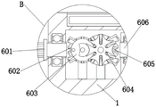
FIG. 3 is an enlarged view of the structure at A in FIG. 2;
FIG. 4 is an enlarged view of the structure at B in FIG. 1;
FIG. 5 is an enlarged view of the structure at C in FIG. 1;
in the figure: 1. the device comprises an operation box, 2, a workbench, 3, a fixing mechanism, 301, a handle, 302, a first threaded rod, 303, a second threaded rod, 304, a vertical column, 305, a transverse plate, 306, a sliding column, 307, a sliding rail, 4, a first sliding chute, 5, a sliding block, 6, an intermittent mechanism, 601, a motor, 602, a first bevel gear set, 603, a rotating wheel, 604, a grooved wheel, 605, a second bevel gear set, 606, a reciprocating screw, 607, a screw nut, 608, a second sliding chute, 7, a hydraulic rod, 8 and a grinding machine.
Detailed Description
The technical solutions in the embodiments of the present invention will be described clearly and completely with reference to the accompanying drawings in the embodiments of the present invention, and it is obvious that the described embodiments are only some embodiments of the present invention, not all embodiments. Based on the embodiments in the present invention, all other embodiments obtained by a person skilled in the art without creative efforts all belong to the protection scope of the present invention.
Example 1
Referring to fig. 1-5, the present invention provides a technical solution: a polishing device for an aluminum curtain wall board comprises an operation box 1, an intermittent mechanism 6 is arranged inside the operation box 1, the intermittent mechanism 6 comprises a motor 601, a first bevel gear set 602, a rotating wheel 603, a grooved wheel 604, a second bevel gear set 605, a reciprocating lead screw 606, a lead screw nut 607 and a second chute 608, the type of the motor 601 is selected according to actual requirements and can meet the requirements for work, the motor 601 is fixedly connected to the outer wall of the operation box 1 through a motor base, an output shaft of the motor 601 is rotatably connected with the operation box 1 through a bearing, the output shaft of the motor 601 is fixedly connected to one end of the first bevel gear set 602, the motor 601 drives the first bevel gear set 602 to rotate, the other end of the first bevel gear set 602 is fixedly connected to the outer wall of a pin shaft, the first bevel gear set 602 drives the pin shaft to rotate, the rotating wheel 603 is fixedly connected to the outer wall of the pin shaft, the pin shaft drives the rotating wheel 603 to rotate, the rotating wheel 603 drives the grooved wheel 604 to intermittently rotate, the rotating wheel 603 is attached to the grooved wheel 604, the grooved wheel 604 to the grooved wheel 604, the grooved wheel 604 is fixedly connected to the outer wall of the other end of the reciprocating lead screw nut, the reciprocating lead screw nut connected to the reciprocating lead screw 606 of the second bevel gear set, the reciprocating lead screw 606 is fixedly connected to the reciprocating chute 606 of the operation box, the reciprocating lead screw 606, the reciprocating nut, the reciprocating lead screw 606 and the reciprocating chute 606, the reciprocating lead screw 606, the reciprocating nut, the reciprocating chute 606 of the reciprocating nut, the reciprocating lead screw 606, the reciprocating nut connected to the reciprocating chute 606, a groove is formed in the operation box 1, the screw nut 607 drives the workbench 2 to slide in the groove, the workbench 2 drives the aluminum curtain wall plate to move, and the workbench 2 is connected with the groove in a sliding manner;
through the cooperation between the motor 601, the first bevel gear set 602, the rotating wheel 603, the grooved wheel 604, the second bevel gear set 605, the reciprocating lead screw 606, the lead screw nut 607 and the second chute 608, the motor 601 drives the first bevel gear set 602 to rotate, the first bevel gear set 602 drives the pin shaft to rotate, the pin shaft drives the rotating wheel 603 to rotate, the rotating wheel 603 drives the grooved wheel 604 to intermittently rotate, the grooved wheel 604 drives the pin shaft to rotate, the pin shaft drives the second bevel gear set 605 to rotate, the second bevel gear set 605 drives the reciprocating lead screw 606 to rotate, and the reciprocating lead screw 606 drives the lead screw nut 607 to slide in the second chute 608, so that when the aluminum curtain wall plate is polished, the polishing machine and the aluminum curtain wall plate synchronously move, the problem that repeated polishing can occur during polishing is solved, and the working efficiency is reduced.
Please refer to fig. 1, the surface rigid coupling of control box 1 has the support frame, first spout 4 has been seted up to the inside of support frame, first spout 4 and 5 sliding connection of slider, hydraulic stem 8 drives slider 5 and slides in first spout 4, the bottom rigid coupling of slider 5 has hydraulic stem 7, hydraulic stem 7 model is selected according to actual demand, satisfy work can, polisher 8 is installed to hydraulic stem 7's bottom, hydraulic stem 7 drives the surface that polisher 8 begins horizontal polishing aluminum curtain wallboard, install electric telescopic handle on the outer wall of hydraulic stem 7, electric telescopic handle drives hydraulic stem 7 and removes, the electric telescopic handle model is selected according to actual demand, satisfy work can, electric telescopic handle passes through the supporting seat rigid coupling on the outer wall of support frame.
Referring to fig. 1, 4 and 5, a fixing mechanism 3 is disposed inside the worktable 2, the fixing mechanism 3 includes a handle 301, a first threaded rod 302, a second threaded rod 303, a vertical column 304, a transverse plate 305, a sliding column 306 and a sliding rail 307, the first threaded rod 302 and the second threaded rod 303 are fixedly connected, the handle 301 drives the first threaded rod 302 and the second threaded rod 303 to rotate, the ends of the first threaded rod 302 and the second threaded rod 303 are rotatably connected with the worktable 2 through bearings, a through hole is formed inside the worktable 2, the handle 301 is mounted on the end of the first threaded rod 302, the first threaded rod 302 and the second threaded rod 303 are both connected with the vertical column 304 through threads, the first threaded rod 302 and the second threaded rod 303 drive the two vertical columns 304 to move back, internal threads are formed inside the two vertical columns 304, the two vertical columns 304 are both connected with the transverse plate 305 in a sliding manner, the two vertical columns 304 and the two transverse plates 305 are both connected with bolts through threads, the bottom of the bolt is rotatably connected with the upright columns 304 through a bearing, the outer walls of the two upright columns 304 are fixedly connected with sliding columns 306, please refer to fig. 1, fig. 4 and fig. 5, a fixing mechanism 3 is arranged inside the workbench 2, the fixing mechanism 3 comprises a handle 301, a first threaded rod 302, a second threaded rod 303, the upright columns 304, a transverse plate 305, the sliding columns 306 and a sliding rail 307, the first threaded rod 302 is fixedly connected with the second threaded rod 303, the handle 301 drives the first threaded rod 302 and the second threaded rod 303 to rotate, the end parts of the first threaded rod 302 and the second threaded rod 303 are rotatably connected with the workbench 2 through bearings, the handle 301 is arranged at the end part of the first threaded rod 302, the first threaded rod 302 and the second threaded rod 303 are both in threaded connection with the upright columns 304, the first threaded rod 302 and the second threaded rod 303 simultaneously drive the two upright columns 304 to move back, internal threads are processed inside the two upright columns 304, the two upright posts 304 are both connected with the transverse plate 305 in a sliding manner, the two upright posts 304 and the two transverse plates 305 are both connected with the bolts through threads, the bottoms of the bolts are rotatably connected with the upright posts 304 through bearings, the bolts drive the transverse posts 305 to rotate, the transverse posts 305 slide in the upright posts 304, the outer walls of the two upright posts 304 are both fixedly connected with sliding posts 306, the two sliding posts 306 are both connected with sliding rails 307 in a sliding manner, and the sliding rails 307 are arranged inside the workbench 2;
through handle 301, first threaded rod 302, second threaded rod 303, stand 304, diaphragm 305, cooperation between traveller 306 and the slide rail 307, rotate handle 301, handle 301 drives first threaded rod 302 and second threaded rod 303 and rotates, first threaded rod 302 and second threaded rod 303 drive two stand 304 back displacements simultaneously, two stand 304 drive traveller 306 and slide in slide rail 307, it fixes to have realized can being based on the aluminium curtain board of different width, fixed range is relatively limited, can not process the problem of different width aluminium curtain boards.
The working principle is as follows:
the aluminum curtain wall plate is placed on the workbench 2 by an operator, the handle 301 is rotated, the handle 301 drives the first threaded rod 302 and the second threaded rod 303 to rotate, the first threaded rod 302 and the second threaded rod 303 simultaneously drive the two upright posts 304 to move backwards, the two upright posts 304 drive the sliding posts 306 to slide in the sliding rails 307, when the two upright posts 304 contact the outer wall of the aluminum curtain wall plate, the handle 301 is stopped to rotate, the bolts drive the cross posts 305 to rotate, the cross posts 305 slide in the upright posts 304, when the cross posts 305 contact the surface of the aluminum curtain wall plate, the bolts are stopped to rotate, rubber sleeves are arranged on the surfaces of the workbench 2, the upright posts 304 and the cross posts 305, the rubber sleeves play a role in protecting the aluminum curtain wall plate, the surface of the aluminum curtain wall plate is prevented from being indented, the hydraulic rod 7, the grinding machine 8 and the electric telescopic rod drive the hydraulic rod 7 to move, the hydraulic rod 8 drives the sliding block 5 to slide in the first sliding groove 4, the hydraulic rod 7 drives the sander 8 to start to polish the surface of the aluminum curtain wall board transversely, the motor 601 is connected with an external power supply, the motor 601 drives the first bevel gear set 602 to rotate, the first bevel gear set 602 drives the pin shaft to rotate, the pin shaft drives the rotating wheel 603 to rotate, the rotating wheel 603 drives the grooved wheel 604 to rotate intermittently, the grooved wheel 604 drives the pin shaft to rotate, the pin shaft drives the second bevel gear set 605 to rotate, the second bevel gear set 605 drives the reciprocating lead screw 606 to rotate, the reciprocating lead screw 606 drives the lead screw nut 607 to slide in the second chute 608, the lead screw nut 607 drives the workbench 2 to slide in the groove, the workbench 2 drives the aluminum curtain wall board to move, when one end of the sander 8, which is punched with the aluminum curtain wall board, is polished to the other end, the rotating wheel 603 is attached to the grooved wheel 604, the grooved wheel 605 starts to rotate the reciprocating lead screw 606, the workbench 2 drives the aluminum curtain wall board to move a part, when the aluminum curtain wall board moves from one end of the operation box 1 to the other end, accomplish polishing to aluminum curtain wall board, stop motor 601, hydraulic stem 7, polisher 8 and electric telescopic handle, on hydraulic stem 8 drove the polisher and gets back to initial position, reverse direction rotation handle 301, will polish good aluminum curtain wall board and take off, transport in the next operation.
Although embodiments of the present invention have been shown and described, it will be appreciated by those skilled in the art that changes, modifications, substitutions and alterations can be made in these embodiments without departing from the principles and spirit of the invention, the scope of which is defined in the appended claims and their equivalents.
Claims (6)
1. The utility model provides an aluminium curtain wall board's processingequipment that polishes, includes control box (1), its characterized in that: an intermittent mechanism (6) is arranged in the operation box (1);
the intermittent mechanism (6) comprises a motor (601), a first bevel gear set (602), a rotating wheel (603), a grooved wheel (604), a second bevel gear set (605), a reciprocating lead screw (606), a lead screw nut (607) and a second sliding groove (608);
the motor (601) is fixedly connected to the outer wall of the operation box (1) through a motor base, the output shaft of the motor (601) is rotatably connected with the operation box (1) through a bearing, the output shaft of the motor (601) is fixedly connected to one end of the first bevel gear set (602), the other end of the first bevel gear set (602) is fixedly connected to the outer wall of the pin shaft, a rotating wheel (603) is fixedly connected to the outer wall of the pin shaft, the rotating wheel (603) is attached to the sheave (604), the sheave (604) is fixedly connected to the outer wall of the other pin shaft, the other end of the second bevel gear set (605) is fixedly connected to the outer wall of the reciprocating lead screw (606), the two pin shafts are rotatably connected with the connecting columns, the two connecting columns are fixedly connected to the inside of the operation box (1), two ends of the reciprocating lead screw (606) are rotatably connected to the operation box (1) through bearings, the reciprocating lead screw (606) is in threaded connection with the lead screw nut (607), the lead screw nut (607) is in sliding connection with the second nut (607), and the sliding chute (608) is fixedly connected to the inside of the operation box (1).
2. The grinding processing device of the aluminum curtain wall board as claimed in claim 1, wherein: the top rigid coupling of screw nut (607) has workstation (2), the inside recess of having seted up of control box (1), workstation (2) and recess sliding connection.
3. The grinding processing device of the aluminum curtain wall board as claimed in claim 1, wherein: the surface rigid coupling of control box (1) has the support frame, first spout (4) have been seted up to the inside of support frame, first spout (4) and slider (5) sliding connection.
4. The grinding processing device of the aluminum curtain wall plate as claimed in claim 3, wherein: the bottom rigid coupling of slider (5) has hydraulic stem (7), polisher (8) are installed to the bottom of hydraulic stem (7).
5. The grinding processing device of the aluminum curtain wall plate as claimed in claim 4, wherein: and an electric telescopic rod is installed on the outer wall of the hydraulic rod (7) and fixedly connected to the outer wall of the support frame through a support seat.
6. The grinding processing device of the aluminum curtain wall board as claimed in claim 2, wherein: a fixing mechanism (3) is arranged in the workbench (2);
the fixing mechanism (3) comprises a handle (301), a first threaded rod (302), a second threaded rod (303), an upright post (304), a transverse plate (305), a sliding column (306) and a sliding rail (307);
first threaded rod (302) and second threaded rod (303) rigid coupling are connected, the tip of first threaded rod (302) and second threaded rod (303) passes through the bearing and rotates with workstation (2) to be connected, handle (301) are installed to the tip of first threaded rod (302), first threaded rod (302) and second threaded rod (303) all with stand (304) threaded connection, two the internal processing of stand (304) has the internal thread, two stand (304) all with diaphragm (305) sliding connection, two stand (304) and two diaphragm (305) all with bolt threaded connection, the bottom of bolt is passed through the bearing and is rotated with stand (304) and is connected, two the equal rigid coupling of outer wall of stand (304) has traveller (306), two traveller (306) all with slide rail (307) sliding connection, the inside at workstation (2) is seted up to slide rail (307).
Priority Applications (1)
| Application Number | Priority Date | Filing Date | Title |
|---|---|---|---|
| CN202221592899.7U CN217668367U (en) | 2022-06-24 | 2022-06-24 | Polishing device for aluminum curtain wall plate |
Applications Claiming Priority (1)
| Application Number | Priority Date | Filing Date | Title |
|---|---|---|---|
| CN202221592899.7U CN217668367U (en) | 2022-06-24 | 2022-06-24 | Polishing device for aluminum curtain wall plate |
Publications (1)
| Publication Number | Publication Date |
|---|---|
| CN217668367U true CN217668367U (en) | 2022-10-28 |
Family
ID=83711637
Family Applications (1)
| Application Number | Title | Priority Date | Filing Date |
|---|---|---|---|
| CN202221592899.7U Active CN217668367U (en) | 2022-06-24 | 2022-06-24 | Polishing device for aluminum curtain wall plate |
Country Status (1)
| Country | Link |
|---|---|
| CN (1) | CN217668367U (en) |
-
2022
- 2022-06-24 CN CN202221592899.7U patent/CN217668367U/en active Active
Similar Documents
| Publication | Publication Date | Title |
|---|---|---|
| CN115415895A (en) | Grinding device is used in stamping die processing | |
| CN215510424U (en) | Polishing mechanism for stainless steel wire drawing process | |
| CN217668367U (en) | Polishing device for aluminum curtain wall plate | |
| CN213828377U (en) | Grinding device is used in automobile parts processing | |
| CN111590445B (en) | Sheet metal part polishing machine and polishing method | |
| CN111922823B (en) | Automatic assembly equipment for electrical control | |
| CN211966988U (en) | Workpiece polishing device for machining | |
| CN218697280U (en) | Calculate key dish metal framework multi-angle grinding device | |
| CN218696929U (en) | Die casting burr grinding device | |
| CN216939908U (en) | Metal test piece polisher | |
| CN214109914U (en) | Ultrahigh-strength aluminum alloy bar processing equipment | |
| CN213351797U (en) | Sheet metal part grinding device | |
| CN221474526U (en) | Guide rail grinding tool | |
| CN210678166U (en) | Aluminum ingot surface polishing system | |
| CN218697103U (en) | Grinding device for metal casting | |
| CN111730445A (en) | Chamfering machine for machining and using method thereof | |
| CN220463355U (en) | Mould production grinding device that precision is high | |
| CN106955931A (en) | Evaporator aluminum comb flattens and makes oblique all-in-one | |
| CN112297184A (en) | Automatic duct piece concrete troweling machine capable of rolling and laterally pushing | |
| CN218397433U (en) | Grinding device is used in automobile parts processing | |
| CN208262462U (en) | A kind of automobile processing plate side high precision grinding machine structure | |
| CN214393581U (en) | Automatic deburring machine for two sides of aluminum alloy panel | |
| CN112719169A (en) | Clamping device for bolt machining | |
| CN221891650U (en) | Metal parts rust removal machine | |
| CN219617317U (en) | Gear shaft forges with equipment of polishing |
Legal Events
| Date | Code | Title | Description |
|---|---|---|---|
| GR01 | Patent grant | ||
| GR01 | Patent grant |