CN217631307U - Quick-dismantling type supporting device for high formwork supporting of aluminum formwork - Google Patents
Quick-dismantling type supporting device for high formwork supporting of aluminum formwork Download PDFInfo
- Publication number
- CN217631307U CN217631307U CN202221812001.2U CN202221812001U CN217631307U CN 217631307 U CN217631307 U CN 217631307U CN 202221812001 U CN202221812001 U CN 202221812001U CN 217631307 U CN217631307 U CN 217631307U
- Authority
- CN
- China
- Prior art keywords
- disc
- vertical
- formwork
- rod
- quick
- Prior art date
- Legal status (The legal status is an assumption and is not a legal conclusion. Google has not performed a legal analysis and makes no representation as to the accuracy of the status listed.)
- Active
Links
Images


Abstract
The utility model particularly relates to a high formwork of aluminium alloy is with quick detach formula strutting arrangement has solved the installation of the high formwork support system of current aluminum alloy and has wasted time and energy, the relatively poor problem of overall stability. A quick-release type supporting device for an aluminum formwork high-support mold comprises upright rods, wherein a top end part of each upright rod is provided with a quick-release head, and a bottom end part of each upright rod is horizontally fixed with a horizontal bottom plate; the vertical rod is a telescopic vertical rod; the outer side wall of each vertical rod is sleeved with a disc buckle disc; a longitudinal supporting rod is horizontally arranged between the two adjacent front and rear vertical rods, and a transverse supporting rod is horizontally arranged between the two adjacent left and right vertical rods; the vertical box body further comprises an I diagonal brace arranged in the horizontal box, an II diagonal brace arranged in the transverse vertical box and an III diagonal brace arranged in the longitudinal vertical box. The utility model discloses a high formwork strutting arrangement's of aluminum alloy convenient installation can be in horizontal direction, vertical and slant drawknot simultaneously, has promoted overall stability, has the cost low, can dismantle fast advantage.
Description
Technical Field
The utility model relates to a building engineering technical field specifically is a high formwork of aluminium template is with quick detach formula strutting arrangement.
Background
Along with the vigorous development of the building market, the aluminum alloy template is more and more widely applied, and has the advantages of good stability, convenient assembly and disassembly, more recycling times, good concrete quality forming and the like as a quick-release mould system. For a structure with the layer height less than 3.3m, the aluminum alloy formwork support system adopts the traditional single vertical rod to independently support. For structures exceeding 3.3m, the single vertical rod independent support system cannot meet the load requirement. Two main aluminum alloy high formwork support systems exist in the current market: firstly, the combination of a single upright support and a steel pipe pull rod is adopted, so that the slenderness ratio of the upright can be reduced, and the stability of the upright is improved; and secondly, the combination of the single upright support and the wheel buckle pull rod is adopted, and the wheel buckle disc is welded on the upright and is connected through the wheel buckle pull rod.
However, practice shows that the existing aluminum alloy high formwork support system has the following problems: firstly, the upright rods are connected with the steel pipe pull rods through specially customized fasteners, so that the installation operation is complicated, and time and labor are wasted; secondly, because the wheel buckle plate has the defects, the simultaneous tie in the horizontal direction, the vertical direction and the oblique direction can not be realized when the layer height is higher, so that the overall stability of the supporting system is poorer.
SUMMERY OF THE UTILITY MODEL
The utility model discloses a solve the installation of the high formwork support system of current aluminum alloy and waste time and energy, the relatively poor problem of overall stability, provide a high quick detach formula strutting arrangement for formwork of aluminum mould board.
The utility model discloses an adopt following technical scheme to realize:
a quick-release type supporting device for an aluminum formwork high-support mold comprises a plurality of vertical rods, wherein the top end part of each vertical rod is provided with a quick-release head, and the bottom end part of each vertical rod is fixed with a horizontal bottom plate with a mounting hole; the upright post is a telescopic upright post; the outer side wall of each upright post is sleeved with N buckling discs which are distributed up and down, and N is a positive integer greater than 2; n longitudinal supporting rods with end parts connected with the disc buckle disc are horizontally arranged between the two adjacent vertical rods in the front-back direction, and N transverse supporting rods with end parts connected with the disc buckle disc are horizontally arranged between the two adjacent vertical rods in the left-right direction; the device also comprises a first diagonal brace arranged in a horizontal square frame formed by enclosing the longitudinal support rods and the transverse support rods, wherein the end part of the first diagonal brace is connected with the disc buckle disc, a second diagonal brace arranged in a transverse vertical square frame formed by enclosing the vertical rods and the transverse support rods, and the end part of the second diagonal brace is connected with the disc buckle disc, and a third diagonal brace arranged in a longitudinal vertical square frame formed by enclosing the longitudinal support rods and the vertical rods, and the end part of the third diagonal brace is connected with the disc buckle disc.
Furthermore, four oval mounting holes distributed in a cross shape and four arc-shaped mounting holes which are circumferentially staggered with the four oval mounting holes are vertically perforated on the disc buckle disc; the end part of the longitudinal supporting rod and the end part of the transverse supporting rod are connected with the disc buckle disc through oval mounting holes; the first diagonal brace, the second diagonal brace and the third diagonal brace are connected with the disc buckle disc through arc-shaped mounting holes.
Furthermore, the upright rod comprises an outer tube positioned on the lower side and an inner tube vertically sleeved with the outer tube, the top end of the outer side wall of the outer tube is provided with an external thread, and the top end of the outer side wall of the outer tube is screwed with an adjusting sleeve of which the outer side wall is provided with two handheld rings; the top end of the side wall of the outer tube is provided with two strip-shaped holes which are opposite to each other in the front-back direction and are vertically arranged in a run-through manner; a plurality of pairs of adjusting holes which are distributed at equal intervals up and down are arranged on the side wall of the inner pipe in a penetrating way, and each pair of adjusting holes are opposite to each other front and back; wherein, a pair of adjusting holes are provided with a U-shaped bolt which penetrates through the strip-shaped hole and is abutted against the upper surface of the adjusting sleeve.
Furthermore, the number of the disc buckle discs is two, and the first group of disc buckle discs comprises a plurality of disc buckle discs fixed on the outer side wall of the outer pipe; the second group of disc buckle discs comprise a plurality of disc buckle discs which are slidably sleeved on the outer side wall of the inner pipe, sliding sleeves which are coaxial with the second group of disc buckle discs and sleeved on the inner pipe are vertically fixed at the centers of the upper surface and the lower surface of the second group of disc buckle discs, and U-shaped bolts I which are abutted to the bottom surfaces of the sliding sleeves and penetrate through a pair of adjusting holes are arranged on the lower sides of the sliding sleeves which are positioned on the lower sides of the sliding sleeves.
Furthermore, two horizontal ear plates distributed on two sides of the disc buckle disc are fixed at two ends of the longitudinal supporting rod, two ends of the transverse supporting rod and two ends of the I-shaped inclined supporting rod, and L-shaped wedges penetrating through the oval mounting holes or the arc mounting holes are arranged on the two horizontal ear plates in a penetrating mode.
Furthermore, connecting plates are fixed at two ends of the second diagonal brace and two ends of the third diagonal brace, a rotating plate is arranged at one side of each connecting plate, and the rotating plates are rotatably connected with the connecting plates through pin shafts; one end of the rotating plate, which is far away from the pin shaft, is fixed with two connecting lug plates which are distributed in parallel and arranged at the same side of the connecting plate, and the two connecting lug plates are provided with L-shaped wedges I which penetrate through the arc-shaped mounting holes in a penetrating manner.
Furthermore, the longitudinal support rod, the transverse support rod, the first inclined support rod, the second inclined support rod and the third inclined support rod can be replaced by an internal threaded pipe positioned in the middle part and an adjusting rod consisting of two screw rods which are screwed at two ends of the internal threaded pipe and have opposite thread directions.
The utility model has the advantages of reasonable design reliably, the convenient installation of high formwork strutting arrangement of aluminum alloy has been realized, and can be in the horizontal direction, vertical and slant drawknot simultaneously, pole setting stability is stronger, overall structure's stability has been promoted, this strutting arrangement's factor of safety has been increased, height-adjustable simultaneously, can be applied to in the building construction of different floor heights, the suitability has effectively been promoted, furthermore, detain the disc through the socket plate between each member and connect, the installation is convenient quick, the efficiency of construction has effectively been improved, it is low to have the cost, can dismantle fast, the advantage that the practicality is strong.
Drawings
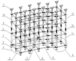
Fig. 1 is a schematic structural diagram of the present invention;
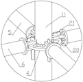
fig. 2 is a schematic structural view of the vertical rod and the disc buckle disc of the present invention;
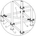
FIG. 3 is an enlarged partial schematic view at A of FIG. 1;
FIG. 4 is an enlarged partial view of FIG. 1 at B;
FIG. 5 is an enlarged partial schematic view at C of FIG. 1;
FIG. 6 is an enlarged partial schematic view at D of FIG. 1;
FIG. 7 is an enlarged partial schematic view at E in FIG. 2;
FIG. 8 is an enlarged partial schematic view at F of FIG. 2;
FIG. 9 is an enlarged partial schematic view at G of FIG. 2;
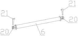
fig. 10 is a schematic structural view of the transverse strut of the present invention;
fig. 11 is a schematic structural view of the adjusting lever of the present invention;
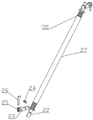
fig. 12 is a schematic structural view of the utility model with the second diagonal brace replaced by the adjusting rod.
In the figure, 1-early dismantling head, 2-mounting hole, 3-horizontal bottom plate, 4-disc buckle disc, 5-longitudinal support rod, 6-transverse support rod, 7-first diagonal support rod, 8-second diagonal support rod, 9-oval mounting hole, 10-arc mounting hole, 11-outer tube, 12-inner tube, 13-hand ring, 14-adjusting sleeve, 15-strip hole, 16-adjusting hole, 17-U-shaped bolt, 18-sliding sleeve, 19-U-shaped bolt I, 20-horizontal ear plate, 21-L-shaped wedge, 22-connecting plate, 23-rotating plate, 24-pin shaft, 25-connecting ear plate, 26-L-shaped wedge I, 27-internal threaded tube and 28-screw rod.
Detailed Description
A quick-release type supporting device for an aluminum formwork high-support mode is shown in attached figures 1-12 and comprises a plurality of vertical rods, wherein the top end part of each vertical rod is provided with an early-release head 1, and the bottom end part of each vertical rod is fixedly provided with a horizontal bottom plate 3 with a mounting hole 2; the upright is a telescopic upright; the outer side wall of each vertical rod is sleeved with four disk buckle disks 4 which are distributed up and down, four longitudinal supporting rods 5 of which the end parts are connected with the disk buckle disks 4 are horizontally arranged between two adjacent vertical rods in the front and back, and four transverse supporting rods 6 of which the end parts are connected with the disk buckle disks 4 are horizontally arranged between two adjacent vertical rods in the left and right; the device also comprises an I diagonal brace 7 which is arranged in a horizontal square frame formed by the enclosure of the longitudinal support rod 5 and the transverse support rod 6 and the end part of which is connected with the disc buckle disc 4, an II diagonal brace 8 which is arranged in a transverse vertical square frame formed by the enclosure of the vertical support rod and the transverse support rod 6 and the end part of which is connected with the disc buckle disc 4, and an III diagonal brace which is arranged in a longitudinal vertical square frame formed by the enclosure of the longitudinal support rod 5 and the vertical support rod and the end part of which is connected with the disc buckle disc 4.
The utility model discloses in the pole setting can provide vertical support effect, vertical strut 5, horizontal strut 6 are used for the vertical and horizontal drawknot, the I diagonal brace 7, the II diagonal brace 8, the III diagonal brace are used for the oblique drawknot, make the whole strutting arrangement structure firm; the vertical rod is a telescopic vertical rod, the height of the vertical rod can be adjusted according to the actual construction site, and the practicability of the utility model is improved; the disc buckling disc 4 is used for connecting the longitudinal supporting rod 5, the transverse supporting rod 6, the first inclined supporting rod 7, the second inclined supporting rod 8 and the third inclined supporting rod, the connection process is convenient and fast, and the construction efficiency is improved.
When the early dismantling device works, the vertical rods are distributed according to the size of the aluminum formwork, the length of the transverse supporting rod 6 and the length of the longitudinal supporting rod 5, the horizontal bottom plate 3 is anchored on the ground by using expansion bolts, and then the lengths of the vertical rods are adjusted, so that the early dismantling head 1 can be arranged at the bottom of the aluminum formwork; then installing each longitudinal support rod 5 and each transverse support rod 6 to enable two ends of each longitudinal support rod 5 and two ends of each transverse support rod 6 to be correspondingly connected to the disc buckle disc 4, and then installing each I diagonal support rod 7, each II diagonal support rod 8 and each III diagonal support rod according to the requirements of the height and the structural stability of the aluminum template to enable two ends of each I diagonal support rod 7, two ends of each II diagonal support rod 8 and two ends of each III diagonal support rod to be correspondingly connected to the disc buckle disc 4; and finally, the early-dismantling head 1 is arranged at the bottom of the aluminum template, so that the installation of the supporting device is completed, and the problems of time and labor waste and poor overall stability in the installation of the conventional aluminum alloy high-formwork supporting system are solved.
As shown in fig. 1-9, four oval mounting holes 9 distributed in a cross shape and four arc mounting holes 10 staggered with the four oval mounting holes 9 in the circumferential direction are vertically perforated on the disc buckle disc 4; the end parts of the longitudinal supporting rods 5 and the transverse supporting rods 6 are connected with the disc buckle disc 4 through oval mounting holes 9; the first diagonal brace 7, the second diagonal brace 8 and the third diagonal brace are connected with the disc buckle disc 4 through arc-shaped mounting holes 10.
The structural design of oval mounting hole 9 has realized independent, convenient connection of longitudinal strut 5, transverse strut 6, and the structural design of arc mounting hole 10 has realized independent, the convenient connection of I diagonal brace 7, II diagonal brace 8, III diagonal brace, and each other does not influence, can independently install, dismantle, has further promoted the simple operation nature when this strutting arrangement ann tears open.
As shown in fig. 1 and fig. 2, the vertical rod includes an outer tube 11 located at the lower side and an inner tube 12 vertically sleeved with the outer tube 11, the top end of the outer side wall of the outer tube 11 is provided with an external thread, and the top end thereof is screwed with an adjusting sleeve 14 having two hand-held rings 13 on the outer side wall; the top end of the side wall of the outer tube 11 is provided with two strip-shaped holes 15 which are opposite to each other in front and back and are vertically arranged in a penetrating way; a plurality of pairs of adjusting holes 16 which are distributed at equal intervals up and down are arranged on the side wall of the inner pipe 12 in a penetrating way, and each pair of adjusting holes 16 are opposite front and back; a U-shaped bolt 17 penetrating through the strip-shaped hole 15 and abutting against the upper surface of the adjusting sleeve 14 is arranged on one of the pair of adjusting holes 16.
The telescopic function of the vertical rod is realized by the structural design of the inner pipe 12 and the outer pipe 11. The structural design of regulation hole 16, U-shaped bolt 17, adjusting sleeve 14, bar hole 15, through the mounted position who changes U-shaped bolt 17 and adjusting sleeve 14's mounting height, firstly can lock the pole setting length after the adjustment, secondly has realized the continuous adjustment of pole setting length for this strutting arrangement can be applicable to the formwork operating mode of co-altitude not, and the suitability further promotes. The structural design of the hand ring 13 makes the screwing process of the adjusting sleeve 14 time-saving and labor-saving.
During installation, the inner pipe 12 is moved up and down until the early dismantling head 1 is close to the bottom of the aluminum template, and then the U-shaped bolt 17 is inserted into the adjusting hole 16 to lock the length of the vertical rod; if the height of the early-dismantling head 1 cannot be connected with the aluminum template, the height of the early-dismantling head 1 is finely adjusted by screwing the adjusting sleeve 14 upwards until the early-dismantling head 1 can be connected with the aluminum template, so that the adjustment of the length of the upright rod is completed.
As shown in fig. 1 and 2, the number of the disc buckle discs 4 is two, and the first group of disc buckle discs 4 comprises a plurality of disc buckle discs 4 fixed on the outer side wall of the outer tube 11; the second group of disc buckling discs 4 comprise a plurality of disc buckling discs 4 which are slidably sleeved on the outer side wall of the inner pipe 12, sliding sleeves 18 which are coaxial with the second group of disc buckling discs 4 and are sleeved on the inner pipe 12 are vertically fixed at the centers of the upper surface and the lower surface of the second group of disc buckling discs 4, and U-shaped bolts I19 which are abutted to the bottom surfaces of the sliding sleeves 18 and penetrate through the pair of adjusting holes 16 are arranged on the lower sides of the sliding sleeves 18 which are located on the lower sides.
U-shaped bolt I19, regulation hole 16, the structural design of sliding sleeve 18 can adjust the mounting height that the disc 4 was buckled to the second group dish, and then adjust vertical support 5, horizontal support 6's mounting height, promoted the flexibility that this strutting arrangement set up the in-process, firstly can be according to the flexible state of pole setting and set up the interval requirement to vertical support 5, horizontal support 6's mounting height carries out nimble adjustment, secondly can avoid the influence that other components in operation place set up this strutting arrangement.
As shown in fig. 1, fig. 3, fig. 4, and fig. 5, two horizontal ear plates 20 distributed on two sides of the disc buckle disc 4 are fixed at two ends of the longitudinal strut 5, two ends of the transverse strut 6, and two ends of the I-th diagonal strut 7, and an L-shaped wedge 21 penetrating through the oval mounting hole 9 or the arc mounting hole 10 is arranged on each of the two horizontal ear plates 20.
This structure is used through the cooperation of horizontal otic placode 20 with L shape wedge 21, has realized that longitudinal strut 5 detains disc 4 with the dish, and transverse strut 6 detains disc 4 with the dish, and the I diagonal brace 7 detains the detachably of disc 4 with the dish and is connected, and connects the simple operation for the construction progress has effectively improved the efficiency of construction.
As shown in fig. 6, connecting plates 22 are fixed at both ends of the second diagonal brace 8 and both ends of the third diagonal brace, a rotating plate 23 is arranged at one side of the connecting plate 22, and the rotating plate 23 is rotatably connected with the connecting plate 22 through a pin 24; two connecting lug plates 25 which are distributed in parallel and arranged at the same side of the connecting plate 22 are fixed at one end of the rotating plate 23 far away from the pin shaft 24, and an L-shaped wedge I26 penetrating through the arc-shaped mounting hole 10 is arranged on the two connecting lug plates 25 in a penetrating manner.
This structural design has realized that II diagonal brace 8 and dish detain disc 4, III diagonal brace and dish detain the detachably of disc 4 and be connected to can detain the nimble angle of adjusting rotor plate 23 of mounted position of disc 4 according to the dish, maneuverability when having improved II diagonal brace 8, III diagonal brace installation.
As shown in fig. 1, 11 and 12, the longitudinal strut 5, the transverse strut 6, the first diagonal strut 7, the second diagonal strut 8 and the third diagonal strut may be replaced by an adjusting rod composed of an internal threaded tube 27 located in the middle and two screws 28 screwed at two ends of the internal threaded tube 27 and having opposite thread directions.
When the standard coiling modulus is not met, namely the transverse size of the supporting device is not matched with the integral multiple length of the transverse supporting rod 6 or the longitudinal size of the supporting device is not matched with the integral multiple length of the longitudinal supporting rod 5, part of the longitudinal supporting rod 5 and the transverse supporting rod 6 are replaced by adjusting rods, so that the flexible adjustment of the whole size of the supporting device can be realized, and the problem of horizontal connection loss caused by the modulus is solved. The first diagonal brace 7, the second diagonal brace 8 and the third diagonal brace are replaced by the adjusting rods, so that the mounting device is suitable for mounting positions with nonstandard sizes, and the influence of the mounting sizes on the first diagonal brace 7, the second diagonal brace 8 and the third diagonal brace is avoided.
When the length of the adjusting rod is adjusted, the internal thread pipe 27 is rotated, and the sleeving length of the two screw rods 28 and the internal thread pipe 27 is synchronously changed, so that the length of the adjusting rod can be adjusted.
In the specific implementation process, the early dismantling head 1 is a common structure in the technical field of constructional engineering, and the appropriate early dismantling head 1 can be selected according to the actual situation; the early dismantling head 1 is sleeved at the top end part of the vertical rod; the number of the mounting holes 2 is four; the number of the first group of disc buckle discs 4 on each upright stanchion is two; the number of the second group of disc buckle discs 4 on each upright rod is two; one or more first inclined supporting rods 7, second inclined supporting rods 8 and third inclined supporting rods can be selected and built according to actual conditions.
Claims (7)
1. A quick-release type supporting device for an aluminum formwork high-support mold comprises a plurality of vertical rods, wherein the top end part of each vertical rod is provided with a early-dismantling head (1), and the bottom end part of each vertical rod is fixed with a horizontal bottom plate (3) with a mounting hole (2); the method is characterized in that: the upright post is a telescopic upright post; the outer side wall of each upright post is sleeved with N buckling discs (4) which are distributed up and down, wherein N is a positive integer greater than 2; n longitudinal supporting rods (5) with the end parts connected with the disc buckle disc (4) are horizontally arranged between the two adjacent vertical rods in the front-back direction, and N transverse supporting rods (6) with the end parts connected with the disc buckle disc (4) are horizontally arranged between the two adjacent vertical rods in the left-right direction; the device also comprises a first inclined stay bar (7) which is arranged in a horizontal square frame formed by enclosing the longitudinal support bar (5) and the transverse support bar (6) and the end part of which is connected with the disc buckle disc (4), a second inclined stay bar (8) which is arranged in a transverse vertical square frame formed by enclosing the vertical support bar and the transverse support bar (6) and the end part of which is connected with the disc buckle disc (4), and a third inclined stay bar which is arranged in a longitudinal vertical square frame formed by enclosing the longitudinal support bar (5) and the vertical support bar and the end part of which is connected with the disc buckle disc (4).
2. The quick-release type supporting device for the high formwork of the aluminum formwork as claimed in claim 1, wherein: four oval mounting holes (9) distributed in a cross shape and four arc-shaped mounting holes (10) which are circumferentially staggered with the four oval mounting holes (9) are vertically arranged on the disc buckle disc (4) in a penetrating manner; the end part of the longitudinal supporting rod (5) and the end part of the transverse supporting rod (6) are connected with the disc buckle disc (4) through oval mounting holes (9); the first diagonal brace (7), the second diagonal brace (8) and the third diagonal brace are connected with the disc buckle disc (4) through arc-shaped mounting holes (10).
3. The quick-release type supporting device for the high formwork of the aluminum formwork as claimed in claim 2, characterized in that: the upright rod comprises an outer tube (11) positioned on the lower side and an inner tube (12) vertically sleeved with the outer tube (11), the top end of the outer side wall of the outer tube (11) is provided with an external thread, and the top end of the outer side wall of the outer tube is screwed with an adjusting sleeve (14) of which the outer side wall is provided with two handheld rings (13); the top end of the side wall of the outer pipe (11) is provided with two strip-shaped holes (15) which are opposite to each other in front and back and are vertically arranged in a penetrating way; a plurality of pairs of adjusting holes (16) which are distributed at equal intervals up and down are arranged on the side wall of the inner pipe (12) in a penetrating way, and each pair of adjusting holes (16) are opposite front and back; u-shaped bolts (17) penetrating through the strip-shaped holes (15) and abutting against the upper surface of the adjusting sleeve (14) are arranged on the pair of adjusting holes (16) in a penetrating manner.
4. The quick-release type supporting device for the high formwork of the aluminum formwork as claimed in claim 3, wherein: the number of the disc buckle discs (4) is two, and the first group of disc buckle discs (4) comprises a plurality of disc buckle discs (4) fixed on the outer side wall of the outer pipe (11); the second group of disc buckling discs (4) comprise a plurality of disc buckling discs (4) which are slidably sleeved on the outer side wall of the inner pipe (12), sliding sleeves (18) which are coaxial with the second group of disc buckling discs and sleeved on the inner pipe (12) are vertically fixed at the centers of the upper surface and the lower surface of the second group of disc buckling discs (4), and U-shaped bolts I (19) which are abutted to the bottom surfaces of the sliding sleeves (18) and penetrate through a pair of adjusting holes (16) are arranged on the lower sides of the sliding sleeves (18) which are located on the lower sides.
5. The quick-release type supporting device for the high formwork of the aluminum formwork as claimed in claim 2, wherein: two horizontal ear plates (20) distributed on two sides of the disc buckle disc (4) are fixed at two ends of the longitudinal supporting rod (5), two ends of the transverse supporting rod (6) and two ends of the I-shaped inclined supporting rod (7), and L-shaped wedges (21) penetrating through the oval mounting holes (9) or the arc mounting holes (10) penetrate through the two horizontal ear plates (20).
6. The quick-release type supporting device for the high formwork of the aluminum formwork as claimed in claim 2, wherein: connecting plates (22) are fixed at two ends of the second diagonal brace (8) and two ends of the third diagonal brace, a rotating plate (23) is arranged at one side of each connecting plate (22), and each rotating plate (23) is rotatably connected with each connecting plate (22) through a pin shaft (24); one end of the rotating plate (23) far away from the pin shaft (24) is fixed with two connecting lug plates (25) which are distributed in parallel and arranged at the same side of the connecting plate (22), and L-shaped wedges I (26) penetrating through the arc-shaped mounting holes (10) are arranged on the two connecting lug plates (25) in a penetrating manner.
7. The quick-release type supporting device for the high formwork of the aluminum formwork as claimed in claim 1, wherein: the longitudinal strut (5), the transverse strut (6), the first diagonal strut (7), the second diagonal strut (8) and the third diagonal strut can be replaced by adjusting rods which are composed of internal threaded pipes (27) positioned in the middle and two screw rods (28) which are screwed at two ends of the internal threaded pipes (27) and are opposite to the thread direction.
Priority Applications (1)
| Application Number | Priority Date | Filing Date | Title |
|---|---|---|---|
| CN202221812001.2U CN217631307U (en) | 2022-07-14 | 2022-07-14 | Quick-dismantling type supporting device for high formwork supporting of aluminum formwork |
Applications Claiming Priority (1)
| Application Number | Priority Date | Filing Date | Title |
|---|---|---|---|
| CN202221812001.2U CN217631307U (en) | 2022-07-14 | 2022-07-14 | Quick-dismantling type supporting device for high formwork supporting of aluminum formwork |
Publications (1)
| Publication Number | Publication Date |
|---|---|
| CN217631307U true CN217631307U (en) | 2022-10-21 |
Family
ID=83634761
Family Applications (1)
| Application Number | Title | Priority Date | Filing Date |
|---|---|---|---|
| CN202221812001.2U Active CN217631307U (en) | 2022-07-14 | 2022-07-14 | Quick-dismantling type supporting device for high formwork supporting of aluminum formwork |
Country Status (1)
| Country | Link |
|---|---|
| CN (1) | CN217631307U (en) |
-
2022
- 2022-07-14 CN CN202221812001.2U patent/CN217631307U/en active Active
Similar Documents
| Publication | Publication Date | Title |
|---|---|---|
| CN208039827U (en) | A kind of constructional form fixing apparatus | |
| CN110424766B (en) | Stair guardrail repairing method | |
| CN111636682A (en) | Turnover external cantilever inclined column supporting system and construction method thereof | |
| CN217631307U (en) | Quick-dismantling type supporting device for high formwork supporting of aluminum formwork | |
| CN210342692U (en) | Single-point embedded part inclined strut device of aluminum alloy template system | |
| CN209585609U (en) | Late poured band support structure | |
| CN108756211B (en) | Aluminum formwork for construction | |
| CN216641397U (en) | Special flat-layer hard protection support frame for socket type disc buckle type external scaffold | |
| CN206530077U (en) | A kind of support frame | |
| CN215802964U (en) | Device for correcting mounting precision of door frame of civil air defense door | |
| CN212612629U (en) | Quick ann tears whole cast-in-place piping lane mounting system who moves changeable formula | |
| CN213573018U (en) | Template clamp for building | |
| CN220057967U (en) | Retaining wall concrete form of layering pouring | |
| CN217680554U (en) | Post-cast strip supporting tool convenient to disassemble | |
| CN219840201U (en) | Steel structure frame suitable for quick assembly | |
| CN217175696U (en) | Laminated floor slab formwork system | |
| CN220014570U (en) | Temporary reinforcing structure for building structure floor slab | |
| CN210636766U (en) | Quick-assembly and disassembly scaffold with anti-toppling function | |
| CN219137703U (en) | Height-adjustable crown beam steel support Z-shaped hanging device | |
| CN219509235U (en) | Assembled autoclaved lightweight concrete board installation reinforcing apparatus | |
| CN217975399U (en) | Simple device for reinforcing stair step formwork | |
| CN220100645U (en) | Wall column template structure for building construction | |
| CN216950421U (en) | New Olympic tunnel construction bow member installation auxiliary device | |
| CN215717117U (en) | Novel detachable external scaffolding is wall spare even | |
| CN215715353U (en) | Deep foundation pit supporting structure capable of preventing deformation |
Legal Events
| Date | Code | Title | Description |
|---|---|---|---|
| GR01 | Patent grant | ||
| GR01 | Patent grant |