CN217629082U - Cutting machine - Google Patents
Cutting machine Download PDFInfo
- Publication number
- CN217629082U CN217629082U CN202221026504.7U CN202221026504U CN217629082U CN 217629082 U CN217629082 U CN 217629082U CN 202221026504 U CN202221026504 U CN 202221026504U CN 217629082 U CN217629082 U CN 217629082U
- Authority
- CN
- China
- Prior art keywords
- fixed
- fixedly arranged
- output shaft
- cutting
- cutting machine
- Prior art date
- Legal status (The legal status is an assumption and is not a legal conclusion. Google has not performed a legal analysis and makes no representation as to the accuracy of the status listed.)
- Active
Links
Images


Abstract
The utility model relates to a cloth processing field discloses a guillootine, the on-line screen storage device comprises a base, fixed cutting table and the portal frame of being provided with in top of base, the fixed driving motor that is provided with in one side of portal frame, the fixed horizontal lead screw that is provided with on driving motor's the output shaft, the fixed nut that is provided with on the output shaft of horizontal lead screw, fixed cover is equipped with on the output shaft of nut and removes the seat, the fixed cylinder that is provided with in front side of removing the seat, the fixed mounting panel that is provided with on the output shaft of cylinder, the bottom of mounting panel is rotated and is provided with four rotor plates. The utility model has the advantages of it is following and effect: can adjust the position of cutting the cutter according to the position that cuts, and can give the flattening to the cloth earlier before cutting, the quality that the fold and influence cut takes place for the cloth when avoiding cutting, be convenient for carry out the dismouting change to the sword that cuts of damage simultaneously, made things convenient for the use.
Description
Technical Field
The utility model relates to a cloth processing technology field, in particular to guillootine.
Background
In cloth production and processing process, need use the guillootine to cut the operation to the cloth, however current guillootine is before cutting, can not carry out the flattening to the cloth, and the cloth easily takes place the fold and influences the quality that cuts when leading to cutting, and inconvenient adjusts the position that cuts, and inconvenient when simultaneously carries out the dismouting change to the sword that cuts after damaging, leads to using very inconvenient, therefore we have proposed a guillootine and have been used for solving above-mentioned problem.
SUMMERY OF THE UTILITY MODEL
The utility model aims at providing a guillootine has and to carry out the flattening to the cloth, guarantees the quality that cuts, and is convenient for adjust the position that cuts, is convenient for carry out the effect of changing to the sword that cuts of damage simultaneously.
The above technical purpose of the present invention can be achieved by the following technical solutions: the automatic cutting machine comprises a base, the fixed cutting platform and the portal frame that are provided with in top of base, the fixed driving motor that is provided with in one side of portal frame, the fixed horizontal lead screw that is provided with on driving motor's the output shaft, the fixed nut that is provided with on the output shaft of horizontal lead screw, fixed cover is equipped with the removal seat on the output shaft of nut, the fixed cylinder that is provided with in front side of removing the seat, the fixed mounting panel that is provided with on the output shaft of cylinder, the bottom of mounting panel is rotated and is provided with four rotor plates, and it is provided with same leveling roller to be located to rotate between two rotor plates with one side, the fixed two reset springs that are provided with in bottom of mounting panel, the spread groove has been seted up to the bottom of mounting panel respectively fixed the setting, the fixed slot cover is equipped with the connecting plate in the bottom of connecting plate, the fixed sword that is provided with in the bottom of connecting plate, the fixed slot has all been seted up to the both sides of connecting plate, the spout has all been seted up to the spout in both sides of spread groove, the fixed extrusion spring that is provided with on one side inner wall of spout, and the one end of extrusion spring is fixed the dead lever activity joint respectively in the fixed slot that corresponds, and the top of two dead levers all is provided with the arm-stay plate fixedly.
Through adopting above-mentioned technical scheme, through driving motor, horizontal lead screw, the cooperation of nut and removal seat, can adjust the position of cutting the cutter according to the position that cuts, through the cylinder, cut the sword, the rotor plate, the cooperation of reset spring and leveling roller, can give the flattening to the cloth earlier before cutting, the quality that the fold and influence cut takes place for the cloth when avoiding cutting, through the dead lever, the arm-tie, the extrusion spring, the fixed slot, the cooperation of connecting plate and spread groove, be convenient for carry out the dismouting to the sword that cuts of damage and change, the use has been made things convenient for.
The utility model discloses a further set up to: the limiting groove has been seted up at the top of portal frame, the sliding sleeve is equipped with the limiting plate in the limiting groove, the fixed top that sets up at the removal seat of limiting plate.
Through adopting above-mentioned technical scheme, through the limiting plate, can carry on spacingly to removing the seat, make it not rotatory with horizontal lead screw together.
The utility model discloses a further set up to: the both sides of removing the seat are all fixed and are provided with the diaphragm, the fixed telescopic link that is provided with in bottom of diaphragm, two telescopic links are all fixed the top that sets up at the mounting panel.
Through adopting above-mentioned technical scheme, through the telescopic link, can lead to the mounting panel for cut that the sword moved down more stably, guarantee the quality of cutting.
The utility model discloses a further set up to: two guide openings are formed in the top of the mounting plate, and the two pull plates are respectively sleeved in the corresponding guide openings in a sliding mode.
Through adopting above-mentioned technical scheme, through the direction mouth, do not hinder the removal of arm-tie, can lead to the arm-tie simultaneously.
The utility model discloses a further set up to: the two fixed rods are respectively sleeved in the corresponding sliding grooves in a sliding manner.
Through adopting above-mentioned technical scheme, can lead to the dead lever, make its more stable that removes.
The utility model discloses a further set up to: the bottom of mounting panel is fixed and is set up four risers, and four rotor plates rotate the front side that sets up at the riser that corresponds respectively.
Through adopting above-mentioned technical scheme, through the riser, conveniently rotate four rotor plates and set up the bottom at the mounting panel.
The utility model has the advantages that:
1. the utility model discloses a driving motor, horizontal lead screw, nut and the cooperation of removing the seat can be adjusted the position of cutting knife according to the position that cuts.
2. The utility model discloses a cylinder, the cooperation of cutting sword, rotor plate, reset spring and flattening roller can give the flattening to the cloth earlier before cutting, and the cloth takes place the fold and influences the quality that cuts when avoiding cutting.
3. The utility model discloses a dead lever, arm-tie, extrusion spring, fixed slot, connecting plate and the cooperation of spread groove, be convenient for carry out the dismouting change to the sword that cuts of damage, made things convenient for the use.
Drawings
In order to more clearly illustrate the technical solutions in the embodiments of the present invention, the drawings needed to be used in the description of the embodiments will be briefly described below, and it is obvious that the drawings in the following description are only some embodiments of the present invention, and it is obvious for those skilled in the art to obtain other drawings without creative efforts.
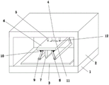
Fig. 1 is a schematic structural view of a cutting machine according to the present invention;
fig. 2 is a cross-sectional view of a cutting machine according to the present invention;
fig. 3 is a schematic structural view of a portion a of a cutting machine according to the present invention;
fig. 4 is a schematic structural diagram of a part B of the cutting machine according to the present invention.
In the figure, 1, a base; 2. a gantry; 3. a cutting table; 4. a cylinder; 5. a telescopic rod; 6. mounting a plate; 7. cutting knife; 8. A rotating plate; 9. a leveling roller; 10. a return spring; 11. pulling a plate; 12. a guide port; 13. a drive motor; 14. a transverse screw rod; 15. a limiting plate; 16. a transverse plate; 17. a nut; 18. a movable seat; 19. connecting grooves; 20. a connecting plate; 21. fixing grooves; 22. a fixing rod; 23. extruding the spring; 24. a chute.
Detailed Description
The technical solution of the present invention will be clearly and completely described below with reference to the specific embodiments. It is obvious that the described embodiments are only some of the embodiments of the present invention, and not all of them. Based on the embodiments of the present invention, all other embodiments obtained by a person skilled in the art without making creative efforts belong to the protection scope of the present invention.
Referring to fig. 1-4, the utility model provides a guillootine, the on-line screen storage device comprises a base 1, base 1's fixed cutting table 3 and the portal frame 2 that is provided with in top, one side of portal frame 2 is fixed and is provided with driving motor 13, the fixed horizontal lead screw 14 that is provided with on driving motor 13's the output shaft, the fixed nut 17 that is provided with on horizontal lead screw 14's the output shaft, fixed cover is equipped with removes seat 18 on nut 17's the output shaft, the fixed cylinder 4 that is provided with in front side that removes seat 18, the fixed mounting panel 6 that is provided with on cylinder 4's the output shaft, the bottom of mounting panel 6 is rotated and is provided with four rotor plates 8, it is provided with same leveling roller 9 to lie in rotating between two rotor plates 8 with one side, the fixed two reset spring 10 that are provided with in mounting panel 6's bottom is fixed respectively, connecting groove 19 has been seted up to the bottom of four reset spring 10, sliding sleeve is equipped with connecting plate 20 in connecting groove 19, the fixed cutting knife 7 that is provided with in the bottom of connecting plate 20, fixed slot 21 has all been seted up to the both sides of connecting plate, chute 24's both sides, fixed slot 24 has been seted up, the fixed slot 24 on the fixed is provided with extrusion spring 23 on one side inner wall, the one end of extrusion spring 23, the fixed dead lever 22 that is provided with two movable dead lever 22 respectively, the dead lever 22 that corresponds, the dead lever internal fixation clamps that corresponds, the dead lever 22 that corresponds respectively, the top that corresponds.
Specifically, a limiting groove is formed in the top of the portal frame 2, a limiting plate 15 is slidably sleeved in the limiting groove, and the limiting plate 15 is fixedly arranged at the top of the movable seat 18.
Specifically, both sides of the movable seat 18 are fixedly provided with a transverse plate 16, the bottom of the transverse plate 16 is fixedly provided with a telescopic rod 5, and the two telescopic rods 5 are fixedly arranged at the top of the mounting plate 6.
Specifically, two guide openings 12 are formed in the top of the mounting plate 6, and the two pull plates 11 are respectively slidably sleeved in the corresponding guide openings 12.
Specifically, the two fixing rods 22 are respectively slidably sleeved in the corresponding sliding grooves 24.
Specifically, four vertical plates are fixedly arranged at the bottom of the mounting plate 6, and the four rotating plates 8 are respectively rotatably arranged on the front sides of the corresponding vertical plates.
The utility model discloses at the during operation, place the cloth that treats cutting on cutting table 3, the position that cuts as required, start driving motor 13, driving motor 13 has driven the rotation of horizontal lead screw 14, under limiting plate 15's is spacing, horizontal lead screw 14 has driven nut 17, remove seat 18 and the lateral shifting who cuts sword 7, and then can be to making cut sword 7 and the position alignment that cuts, then drive mounting panel 6 through cylinder 4, rotor plate 8, leveling roller 9 and the moving down that cuts sword 7, before cutting sword 7 cuts the cloth, leveling roller 9 contacts with the cloth earlier, when mounting panel 6 continues to move down, two rotor plates 8 are pressed and are kept away from each other and extrude reset spring 10, two rotor plates 8 keep away from each other and have driven two leveling roller 9 and roll on the cloth that two leveling roller 9 kept away from each other, and then can give the flattening to the cloth of cutting position, the cloth takes place fold and influence the quality that cuts when avoiding cutting when cutting, then cut sword 7 and continue to move down to cut the cloth, when the needs to change the sword 7 of damage, two pulling plates 11, and then the dead lever 21 is pushed the dead lever and the dead lever is taken and is not pushed the dead lever and is taken to the dead lever and is fixed to the dead lever 20 and is not pushed the dead lever and is gone into the dead lever and is pressed to the dead lever in the dead lever 7 and is not pushed the dead lever and is fixed on the dead lever 7 this moment, and is got 20 respectively to the dead lever 7, then can be changed to the dead lever 7, then cut sword 7 to the dead lever 7.
Claims (6)
1. The cutting machine comprises a base (1) and is characterized in that a cutting table (3) and a portal frame (2) are fixedly arranged at the top of the base (1), a driving motor (13) is fixedly arranged on one side of the portal frame (2), a transverse lead screw (14) is fixedly arranged on an output shaft of the driving motor (13), a nut (17) is fixedly arranged on an output shaft of the transverse lead screw (14), a moving seat (18) is fixedly arranged on an output shaft of the nut (17), a cylinder (4) is fixedly arranged on the front side of the moving seat (18), a mounting plate (6) is fixedly arranged on an output shaft of the cylinder (4), four rotating plates (8) are rotatably arranged at the bottom of the mounting plate (6), the same leveling roller (9) is rotatably arranged between the two rotating plates (8) positioned on the same side, two reset springs (10) are fixedly arranged at the bottom of the mounting plate (6), the bottoms of the four reset springs (10) are respectively fixedly arranged on the corresponding rotating plates (8), a connecting groove (19) is formed in the bottom of the mounting plate (6), a connecting plate (20) is sleeved with a fixing groove (19), a connecting plate (20) is sleeved with an inner sliding connecting plate (20), and two sides of the cutting knife (7) are respectively arranged on two sides of the fixing knife (21), spout (24) have all been seted up to the both sides of spread groove (19), fixed extrusion spring (23) of being provided with on the one side inner wall of spout (24), the fixed dead lever (22) that is provided with of one end of extrusion spring (23), two dead levers (22) activity joint respectively in fixed slot (21) that correspond, the top of two dead levers (22) is all fixed and is provided with arm-tie (11).
2. The cutting machine according to claim 1, wherein: the limiting groove has been seted up at the top of portal frame (2), the sliding sleeve is equipped with limiting plate (15) in the limiting groove, limiting plate (15) are fixed to be set up at the top that removes seat (18).
3. The cutting machine according to claim 1, wherein: both sides of moving seat (18) all are fixed and are provided with diaphragm (16), the bottom of diaphragm (16) is fixed and is provided with telescopic link (5), and two telescopic links (5) all are fixed the top that sets up at mounting panel (6).
4. The cutting machine as set forth in claim 1, characterized in that: two guide openings (12) are formed in the top of the mounting plate (6), and the two pull plates (11) are respectively sleeved in the corresponding guide openings (12) in a sliding mode.
5. The cutting machine as set forth in claim 1, characterized in that: the two fixed rods (22) are respectively sleeved in the corresponding sliding grooves (24) in a sliding manner.
6. The cutting machine as set forth in claim 1, characterized in that: the bottom of mounting panel (6) is fixed to be set up four risers, and four rotor plates (8) rotate the front side that sets up at the riser that corresponds respectively.
Priority Applications (1)
| Application Number | Priority Date | Filing Date | Title |
|---|---|---|---|
| CN202221026504.7U CN217629082U (en) | 2022-04-28 | 2022-04-28 | Cutting machine |
Applications Claiming Priority (1)
| Application Number | Priority Date | Filing Date | Title |
|---|---|---|---|
| CN202221026504.7U CN217629082U (en) | 2022-04-28 | 2022-04-28 | Cutting machine |
Publications (1)
| Publication Number | Publication Date |
|---|---|
| CN217629082U true CN217629082U (en) | 2022-10-21 |
Family
ID=83651445
Family Applications (1)
| Application Number | Title | Priority Date | Filing Date |
|---|---|---|---|
| CN202221026504.7U Active CN217629082U (en) | 2022-04-28 | 2022-04-28 | Cutting machine |
Country Status (1)
| Country | Link |
|---|---|
| CN (1) | CN217629082U (en) |
Cited By (1)
| Publication number | Priority date | Publication date | Assignee | Title |
|---|---|---|---|---|
| CN116277201A (en) * | 2023-05-18 | 2023-06-23 | 杭州职业技术学院 | Drawing cutting device for industrial design |
-
2022
- 2022-04-28 CN CN202221026504.7U patent/CN217629082U/en active Active
Cited By (2)
| Publication number | Priority date | Publication date | Assignee | Title |
|---|---|---|---|---|
| CN116277201A (en) * | 2023-05-18 | 2023-06-23 | 杭州职业技术学院 | Drawing cutting device for industrial design |
| CN116277201B (en) * | 2023-05-18 | 2023-12-22 | 杭州职业技术学院 | Drawing cutting device for industrial design |
Similar Documents
| Publication | Publication Date | Title |
|---|---|---|
| CN217629082U (en) | Cutting machine | |
| CN111873003A (en) | Agricultural byproduct slicing tool with lifting function and slicing method thereof | |
| CN109465659A (en) | A kind of stainless steel square tube cutting method and device | |
| CN219465100U (en) | Processing cutting equipment for hollow plastic plate | |
| CN209190311U (en) | A kind of stainless steel square tube cutter device | |
| CN112170935A (en) | Multi-directional pipeline cutting device convenient to position | |
| CN210756351U (en) | Leveling traction system for sheet steel processing | |
| CN116945249A (en) | Positioning and cutting device for producing silica gel heating plates and application method thereof | |
| CN218983373U (en) | Aluminum plate shearing and conveying device | |
| CN219026341U (en) | Cloth cutting machine that facilitates use | |
| CN211247905U (en) | Part punching and shearing device | |
| CN219522393U (en) | Automatic material shaping all-in-one that cuts off of bamboo wood processing | |
| CN208649127U (en) | A kind of glass processing cutter device | |
| CN205616322U (en) | Automatic winder pole piece removes pay -off blank device | |
| CN217677306U (en) | Combined glass processing and cutting device | |
| CN215549064U (en) | Multi-cutter slitting equipment with adjusting mechanism | |
| CN218109601U (en) | Furnace tube cutting equipment | |
| CN219430357U (en) | Fabric cutting machine | |
| CN219132399U (en) | Cutting machine convenient to adjust cutting size | |
| CN218965499U (en) | Cut interval adjustable clipper | |
| CN219706282U (en) | Cutter die for producing degradable film bags | |
| CN219543316U (en) | Plastic film side cut equipment with adjustable | |
| CN220805689U (en) | Aluminium bar shearing machine | |
| CN218612969U (en) | Steel plate punching device | |
| CN219748153U (en) | Sponge cutting device |
Legal Events
| Date | Code | Title | Description |
|---|---|---|---|
| GR01 | Patent grant | ||
| GR01 | Patent grant |