CN217579860U - Safety warning device for building construction management - Google Patents
Safety warning device for building construction management Download PDFInfo
- Publication number
- CN217579860U CN217579860U CN202221121736.0U CN202221121736U CN217579860U CN 217579860 U CN217579860 U CN 217579860U CN 202221121736 U CN202221121736 U CN 202221121736U CN 217579860 U CN217579860 U CN 217579860U
- Authority
- CN
- China
- Prior art keywords
- outer frame
- clamping
- rod
- fixed
- screw
- Prior art date
- Legal status (The legal status is an assumption and is not a legal conclusion. Google has not performed a legal analysis and makes no representation as to the accuracy of the status listed.)
- Active
Links
Images
Abstract
The utility model provides a safety warning device is used in construction management, operate more laborsaving, convenient. The warning board is arranged in the outer frame; the bracket is fixed on the base; the outer frame is arranged on the bracket in a lifting way; the outer frame lifting screw is vertically arranged and is hinged to the bottom of the outer frame, and the outer frame lifting screw is in threaded connection with the support; the vertical rod is vertically and slidably mounted on the supporting plate, one end of the vertical rod is fixedly provided with a first clamping plate, and the other end of the vertical rod is fixedly provided with a fixing block; one end of the spring is connected with the fixed block, and the other end of the spring is connected with the supporting plate; the upper and lower sides of the warning board are clamped and fixed by the first clamping plates of the two groups of first clamping mechanisms; one end of the connecting rod is fixed with the screw rod sliding block, the other end of the connecting rod is fixed with the second clamping plate, and the screw rod sliding block is slidably arranged in the outer frame; the left side and the right side of the warning board are clamped and fixed by second clamping plates of the two groups of second clamping mechanisms; the lead screw level sets up, and rotates and install on the frame, and the lead screw slider of two sets of second clamping mechanism all installs on the lead screw.
Description
Technical Field
The utility model relates to a safety warning device is used in construction management.
Background
The building construction refers to production activities in engineering construction implementation stages, is a construction process of various buildings, can also be a process of changing various lines on design drawings into physical objects in specified places, and comprises the processes of foundation engineering construction, main structure construction, roofing engineering construction, curtain wall engineering construction, decoration engineering construction and the like.
Safety warning device is used in construction management among the prior art, be provided with the warning frame on warning frame, the warning sign sets up in the warning frame, the department all passes threaded sleeve all around on the warning frame, pass the threaded rod in the threaded sleeve, the threaded rod injects one in the warning frame and serves and be provided with the cardboard, for the installation to the not unidimensional warning sign in order to be convenient for, at first move the warning sign to the warning frame in, the threaded rod is rotated respectively to the subdividing, drive the cardboard and support the side department tight to the warning sign, realize the installation work to the warning sign in the warning frame. But when actual operation, need move the warning sign to the frame in to when rotating the threaded rod, still need the manual work to drag the warning sign, make the threaded rod can be smooth drive the cardboard support tightly to the warning sign on, the operation is comparatively hard like this, consequently remains to be improved.
SUMMERY OF THE UTILITY MODEL
The utility model aims to overcome the above-mentioned not enough that exists among the prior art, and provide a construction safety warning device for management that structural design is reasonable, operate labour saving more, convenience.
The utility model provides a technical scheme that above-mentioned problem adopted is: a safety warning device for building construction management comprises a base, an outer frame and a warning board; the warning board is arranged in the outer frame; the method is characterized in that: the device also comprises a bracket, a screw rod, an outer frame lifting screw rod, a first clamping mechanism and a second clamping mechanism; the bracket is fixed on the base; the outer frame is arranged on the bracket in a lifting way; the outer frame lifting screw is vertically arranged and is hinged to the bottom of the outer frame, and the outer frame lifting screw is in threaded connection with the support; the first clamping mechanism comprises a supporting plate, a first clamping plate, a vertical rod, a fixing block and a spring; the vertical rod is vertically and slidably mounted on the supporting plate, a first clamping plate is fixedly arranged at one end of the vertical rod, and a fixing block is fixedly arranged at the other end of the vertical rod; one end of the spring is connected with the fixed block, and the other end of the spring is connected with the supporting plate; the first clamping mechanisms are arranged in two groups and are respectively arranged on the upper side and the lower side in the outer frame, and the first clamping plates of the two groups of first clamping mechanisms clamp and fix the upper side and the lower side of the warning board; the second clamping mechanism comprises a connecting rod, a second clamping plate and a screw rod sliding block; one end of the connecting rod is fixed with the screw rod sliding block, the other end of the connecting rod is fixed with the second clamping plate, and the screw rod sliding block is slidably arranged in the outer frame; the two groups of second clamping mechanisms are respectively positioned at the left side and the right side in the outer frame, and the left side and the right side of the warning board are clamped and fixed by second clamping plates of the two groups of second clamping mechanisms; the lead screw level sets up, and rotates and install on the frame, and the lead screw slider of two sets of second clamping mechanism all installs on the lead screw.
The bottom of base be provided with the gyro wheel.
The utility model also comprises a fixed rod and a threaded rod; the supporting plate of the upper first clamping mechanism is fixed on the outer frame through a fixing rod; a supporting plate of the first clamping mechanism at the lower side is in threaded connection with the threaded rod; the threaded rod is vertically arranged, and the bottom end of the threaded rod is rotatably arranged on the outer frame.
Frame seted up the spout, lead screw slider slidable mounting is in the spout.
The utility model also comprises a rotating wheel, a screw rod and a rotating wheel fixed connection.
The lead screw on both sides screw thread opposite direction who is connected with two sets of second clamping mechanism lead screw sliders.
The utility model also comprises a rack and a gear, wherein the rack is horizontally arranged and is fixedly arranged on the connecting rod of one group of second clamping mechanisms; the threaded rod is fixedly sleeved with a gear which is meshed with the rack.
First splint and second splint all be the U-shaped.
The support of the utility model is U-shaped.
The utility model discloses still include the guide bar, the guide bar is vertical to be fixed in the bottom of frame, and guide bar slidable mounting is on the support.
Compared with the prior art, the utility model, have following advantage and effect: when installing the warning sign in the frame, at first, directly move the warning sign and place between two sets of first splint, under the spring action of spring, through fixed block and montant, can drive first splint centre gripping to the warning sign on, then relieve the warning sign, cooperate the support of two sets of first splint, remove two sets of second splint in the frame, utilize the second splint to press from both sides tightly to fix it on the warning sign, and through rotating frame lifting screw, can be according to actual conditions's needs, highly carry out nimble regulation to the warning sign, operate more laborsaving, convenient.
Drawings
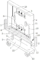
Fig. 1 is a schematic structural diagram of an embodiment of the present invention.
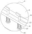
Fig. 2 is an enlarged schematic view of a portion a in fig. 1.
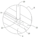
Fig. 3 is an enlarged schematic view of a portion B in fig. 1.
Detailed Description
The present invention will be described in further detail by way of examples with reference to the accompanying drawings, which are illustrative of the present invention and are not intended to limit the present invention.
The embodiment of the utility model provides a including base 1, support 2, support column 3, frame 4, warning sign 5, rack 9, threaded rod 7, lead screw 19, frame lifting screw 22, guide bar 12, gyro wheel 13, runner 18, dead lever 23, first clamping mechanism and second clamping mechanism.
The bottom both sides department of base 1 all is provided with gyro wheel 13.
Support 2 sets up in the top of base 1, and support 2 passes through support column 3 to be fixed on base 1.
The outer frame 4 is arranged on the bracket 2; the guide rods 12 are vertically fixed at the two sides of the bottom of the outer frame 4 and movably pass through the through holes on the support 2, so that the guide rods 12 are slidably arranged on the support 2, and the outer frame 4 is arranged on the support 2 in a lifting manner; the outer frame lifting screw 22 is vertically arranged and is hinged to the middle of the bottom of the outer frame 4, the outer frame lifting screw 22 penetrates through a threaded hole in the support 2, and thus the outer frame lifting screw 22 is in threaded connection with the support 2; when the outer frame lifting screw 22 is rotated, the height of the warning board 5 in the outer frame 4 can be adjusted according to the requirement of actual conditions under the limiting action of the guide rod 12, and the use is more flexible.
The warning board 5 is arranged in the outer frame 4.
The first clamping mechanism comprises a support plate 6, a first clamping plate 14, a vertical rod 15, a fixing block 16 and a spring 17. The vertical rods 15 are vertically and slidably arranged on the supporting plate 6, and two vertical rods 15 are arranged on the supporting plate 6; a first clamping plate 14 is fixedly arranged at one end of the vertical rod 15, and a fixed block 16 is fixedly arranged at the other end of the vertical rod 15; the spring 17 is sleeved on the vertical rod 15, one end of the spring is connected with the fixed block 16, and the other end of the spring is connected with the supporting plate 6. The two groups of first clamping mechanisms are respectively positioned at the upper side and the lower side in the outer frame 4, the two groups of first clamping mechanisms are oppositely arranged, and the upper side and the lower side of the warning board 5 are clamped and fixed by the first clamping plates 14 of the two groups of first clamping mechanisms.
The support plate 6 of the upper first clamping mechanism is fixedly mounted on the outer frame 4 by means of the fixing rod 23, so that the upper first clamping mechanism is mounted on the inner upper side of the outer frame 4. Threaded holes are formed in two sides of a supporting plate 6 of the first clamping mechanism on the lower side, a threaded rod 7 is arranged in the threaded holes in a penetrating mode, and the threaded rod 7 is in threaded connection with the supporting plate 6; the threaded rod 7 is vertically arranged, and the bottom end of the threaded rod is rotatably arranged on the inner wall of the outer frame 4, so that the first clamping mechanism at the lower side is arranged at the lower side in the outer frame 4;
when the threaded rod 7 is rotated, the supporting plate 6 of the first clamping mechanism at the lower side moves up and down on the threaded rod 7 to drive the first clamping plate 14 of the first clamping mechanism at the lower side to clamp the warning board 5, so that the clamping is firmer.
The second clamping mechanism comprises a connecting rod 10, a second clamping plate 11 and a screw rod slide block 21. One end of the connecting rod 10 is fixed with the screw rod slide block 21, the other end is fixed with the second clamping plate 11, the lower wall of the outer frame 4 is provided with a chute 20, the screw rod slide block 21 is slidably arranged in the chute 20, and thus the screw rod slide block 21 is slidably arranged in the outer frame 4. The two groups of second clamping mechanisms are respectively positioned at the left side and the right side of the outer frame 4, the two groups of second clamping mechanisms are oppositely arranged, and the left side and the right side of the warning board 5 are clamped and fixed by the second clamping plates 11 of the two groups of second clamping mechanisms.
The screw rod 19 is horizontally arranged and rotatably installed on the outer frame 4, and the screw rod 19 penetrates out of the right end of the outer frame 4 and is fixedly connected with the rotating wheel 18. Threaded holes are formed in the screw rod sliding blocks 21 of the two groups of second clamping mechanisms, the screw rod 19 penetrates through the threaded holes, the screw rod sliding blocks 21 of the two groups of second clamping mechanisms are installed on the screw rod 19, the screw rod sliding blocks 21 are in threaded connection with the screw rod 19, the screw rod 19 is a bidirectional threaded rod, the two side threads connected with the screw rod sliding blocks 21 of the two groups of second clamping mechanisms on the screw rod 19 are opposite in direction, when the screw rod 19 is rotated, the screw rod sliding blocks 21 of the two groups of second clamping mechanisms move oppositely or oppositely, when the screw rod 19 is rotated by the rotating wheel 18, the screw rod sliding blocks 21 move on the screw rod 19, the second clamping plates 11 which can drive the two sides synchronously are clamped on the warning board 5 and are fixed, and the operation is simpler and more convenient.
The rack 9 is horizontally arranged and fixedly arranged on a connecting rod 10 of the second clamping mechanism on the right side; the rack 9 extends to the position of the threaded rod 7, the threaded rod 7 is fixedly sleeved with a gear 8, and the gear 8 is meshed with the rack 9. The connecting rod 10 drives the second clamping plate 11 to move and clamp to the warning board 5, simultaneously, the teeth on the rack 9 drive the gear 8 to rotate so as to drive the threaded rod 7 to rotate, the first clamping plate 14 of the lower side first clamping mechanism automatically clamps the warning board 5, the structure is simple, the function is practical,
the first clamping plate 14 and the second clamping plate 11 are both U-shaped.
The working principle of the embodiment of the application is as follows: firstly, the warning board 5 is directly moved and placed between two groups of first clamping plates 14, under the action of the elastic force of a spring 17, the first clamping plates 14 can be driven to be clamped on the warning board 5 through fixing blocks 16 and vertical rods 15, the warning board 5 is supported, then a screw 19 is directly rotated by using a rotating wheel 18, a screw slider 21 drives a second clamping plate 11 at one end of a connecting rod 10 to be clamped to the left side and the right side of the warning board 5 in a sliding groove 20, the connecting rod 10 drives a rack 9 to move while moving, a movable threaded rod 7 is hung through a gear 8 to rotate, a supporting plate 6 drives the first clamping plate 14 to be clamped on the warning board 5 on the threaded rod 7 to realize the installation work of the warning board 5, the operation is simpler and more convenient, and the outer frame lifting screw 22 can also be rotated on a support 2 according to actual conditions, the outer frame lifting screw 22 drives the outer frame 4 to move to adjust the height of the warning board 5, and finally, the device is pushed to a warning position by using the rolling of the rolling wheel 13.
The above embodiments are preferred embodiments of the present application, and the protection scope of the present application is not limited by the above embodiments, so: all equivalent changes made according to the structure, shape and principle of the present application shall be covered by the protection scope of the present application.
Claims (10)
1. A safety warning device for building construction management comprises a base, an outer frame and a warning board; the warning board is arranged in the outer frame; the method is characterized in that: the device also comprises a bracket, a screw rod, an outer frame lifting screw rod, a first clamping mechanism and a second clamping mechanism; the bracket is fixed on the base; the outer frame is arranged on the bracket in a lifting way; the outer frame lifting screw is vertically arranged and is hinged to the bottom of the outer frame, and the outer frame lifting screw is in threaded connection with the support; the first clamping mechanism comprises a supporting plate, a first clamping plate, a vertical rod, a fixing block and a spring; the vertical rod is vertically and slidably mounted on the supporting plate, a first clamping plate is fixedly arranged at one end of the vertical rod, and a fixing block is fixedly arranged at the other end of the vertical rod; one end of the spring is connected with the fixed block, and the other end of the spring is connected with the supporting plate; the first clamping mechanisms are arranged in two groups and are respectively arranged on the upper side and the lower side in the outer frame, and the first clamping plates of the two groups of first clamping mechanisms clamp and fix the upper side and the lower side of the warning board; the second clamping mechanism comprises a connecting rod, a second clamping plate and a screw rod sliding block; one end of the connecting rod is fixed with the screw rod sliding block, the other end of the connecting rod is fixed with the second clamping plate, and the screw rod sliding block is slidably arranged in the outer frame; the two groups of second clamping mechanisms are respectively positioned at the left side and the right side in the outer frame, and the left side and the right side of the warning board are clamped and fixed by second clamping plates of the two groups of second clamping mechanisms; the lead screw level sets up, and rotates and install on the frame, and the lead screw slider of two sets of second clamping mechanism all installs on the lead screw.
2. The safety warning device for building construction management according to claim 1, characterized in that: the bottom of the base is provided with rollers.
3. The safety warning device for building construction management according to claim 1, characterized in that: the fixing rod and the threaded rod are further included; the supporting plate of the upper first clamping mechanism is fixed on the outer frame through a fixing rod; a supporting plate of the first clamping mechanism at the lower side is in threaded connection with the threaded rod; the threaded rod is vertically arranged, and the bottom end of the threaded rod is rotatably arranged on the outer frame.
4. The safety warning device for building construction management according to claim 1, characterized in that: the outer frame is provided with a sliding groove, and the screw rod sliding block is slidably arranged in the sliding groove.
5. The safety warning device for building construction management according to claim 1, characterized in that: the screw rod is fixedly connected with the rotating wheel.
6. The safety warning device for building construction management according to claim 1, characterized in that: and the screw threads on two sides of the screw rod connected with the two groups of screw rod sliding blocks of the second clamping mechanism are opposite in direction.
7. The safety warning device for building construction management according to claim 3, characterized in that: the rack is horizontally arranged and is fixedly arranged on the connecting rod of one group of the second clamping mechanisms; the threaded rod is fixedly sleeved with a gear which is meshed with the rack.
8. The safety warning device for building construction management according to claim 1, characterized in that: the first clamping plate and the second clamping plate are both U-shaped.
9. The safety warning device for building construction management according to claim 1, characterized in that: the bracket is U-shaped.
10. The safety warning device for building construction management according to claim 1, characterized in that: still include the guide bar, the guide bar is vertical to be fixed in the bottom of frame, and guide bar slidable mounting is on the support.
Priority Applications (1)
| Application Number | Priority Date | Filing Date | Title |
|---|---|---|---|
| CN202221121736.0U CN217579860U (en) | 2022-05-11 | 2022-05-11 | Safety warning device for building construction management |
Applications Claiming Priority (1)
| Application Number | Priority Date | Filing Date | Title |
|---|---|---|---|
| CN202221121736.0U CN217579860U (en) | 2022-05-11 | 2022-05-11 | Safety warning device for building construction management |
Publications (1)
| Publication Number | Publication Date |
|---|---|
| CN217579860U true CN217579860U (en) | 2022-10-14 |
Family
ID=83551543
Family Applications (1)
| Application Number | Title | Priority Date | Filing Date |
|---|---|---|---|
| CN202221121736.0U Active CN217579860U (en) | 2022-05-11 | 2022-05-11 | Safety warning device for building construction management |
Country Status (1)
| Country | Link |
|---|---|
| CN (1) | CN217579860U (en) |
-
2022
- 2022-05-11 CN CN202221121736.0U patent/CN217579860U/en active Active
Similar Documents
| Publication | Publication Date | Title |
|---|---|---|
| CN111070309A (en) | Drilling equipment is used in processing of polymer tubular product | |
| CN108390625B (en) | Portable solar photovoltaic support | |
| CN216157259U (en) | Adjustable supporting device with safety for constructional engineering | |
| CN217579860U (en) | Safety warning device for building construction management | |
| CN208854793U (en) | A kind of plastic tube Linear multi-head punch device | |
| CN215564443U (en) | House building engineering pours template support frame with flexible regulation reinforcement type room roof beam | |
| CN216743623U (en) | Intelligent on-line measuring device for pipeline supporting member | |
| CN107434139B (en) | Adjustable tensioning mechanism of conveying device | |
| CN216007195U (en) | Pipeline positioning support for water supply and drainage engineering | |
| CN210877699U (en) | Top plate drilling support | |
| CN114920148A (en) | Positioning and adjusting auxiliary mounting device for mounting electromechanical equipment | |
| CN211180520U (en) | Tensioning support for fixing screen | |
| CN211920744U (en) | Steel reinforcement cage lifting device | |
| CN220203593U (en) | Construction fixing device | |
| CN216868028U (en) | Base support for mining vacuum starter | |
| CN214466625U (en) | Adjusting bracket for pipeline installation | |
| CN216732070U (en) | Positioning device for cutting PVC (polyvinyl chloride) floor | |
| CN220209883U (en) | Cable supporting pre-tightening bracket | |
| CN220218152U (en) | Clamping device for air conditioner controller panel production and processing | |
| CN218540779U (en) | Device convenient to well lid is installed and is dismantled | |
| CN217890734U (en) | A pipeline butt joint fixing device for water plant construction | |
| CN220190355U (en) | Adjustable cable support | |
| CN217223701U (en) | Drilling equipment is used in production of stainless steel table | |
| CN213919645U (en) | Plastic corrugated welding machine | |
| CN219342680U (en) | Leather embossing machine |
Legal Events
| Date | Code | Title | Description |
|---|---|---|---|
| GR01 | Patent grant | ||
| GR01 | Patent grant |