CN217571583U - Vertical positioning and pressing mechanism of welding fixture - Google Patents
Vertical positioning and pressing mechanism of welding fixture Download PDFInfo
- Publication number
- CN217571583U CN217571583U CN202221357378.3U CN202221357378U CN217571583U CN 217571583 U CN217571583 U CN 217571583U CN 202221357378 U CN202221357378 U CN 202221357378U CN 217571583 U CN217571583 U CN 217571583U
- Authority
- CN
- China
- Prior art keywords
- arm
- fixed plate
- vertical
- guide
- block
- Prior art date
- Legal status (The legal status is an assumption and is not a legal conclusion. Google has not performed a legal analysis and makes no representation as to the accuracy of the status listed.)
- Active
Links
Images


Landscapes
- Jigs For Machine Tools (AREA)
Abstract
The utility model discloses a welding jig's vertical location hold-down mechanism, including the fixed plate, there is slim cylinder at the lower fixed surface of this fixed plate the upper surface of fixed plate is connected with two guide blocks through the supporting shoe, is provided with the connecting block between two guide blocks and presses the arm, the telescopic link of slim cylinder upwards passes behind the fixed plate and is connected with this connecting block, has still seted up relative spacing groove on two guide blocks slide spacing in the spacing groove and have the uide pin, the connecting block pass through the uide pin with the lower extreme of pressing the arm is connected, the upper end of pressing the arm is formed with the pressure head the guide block is close to be connected with perpendicular stopper on pressure head one side. The remarkable effects are as follows: the movement track of the thin cylinder connecting pressure head is limited to improve the stability of part positioning, and smooth opening of the cylinder connecting and positioning mechanism is ensured.
Description
Technical Field
The utility model relates to automobile parts production frock clamp technical field, concretely relates to welding jig's vertical location hold-down mechanism.
Background
Because the common thin air cylinders used in the production of the existing automobile parts are all rotationally compressed, the three-axis cylinder can meet the vertical compression, but the operable space is small after the three-axis cylinder is opened, and the influence on the production efficiency and the operability is low.
Disclosure of Invention
The utility model is not enough to prior art, the utility model aims at providing a welding jig's vertical location hold-down mechanism can improve the maneuverability after hold-down mechanism opens, simplifies the part location of the location department of being not convenient for.
In order to achieve the purpose, the utility model adopts the technical proposal as follows:
the utility model provides a welding jig's vertical location hold-down mechanism which the key lies in: including the fixed plate, be fixed with slim cylinder at the lower fixed surface of this fixed plate the upper surface of fixed plate is connected with two guide blocks through the supporting shoe, is provided with connecting block and pressure arm between two guide blocks, the telescopic link of slim cylinder upwards passes behind the fixed plate to be connected with this connecting block, has still seted up relative spacing groove on two guide blocks slide spacing in the spacing groove and have the uide pin, the connecting block pass through the uide pin with the lower extreme of pressing the arm is connected, the upper end of pressing the arm is formed with the pressure head the guide block is close to be connected with perpendicular stopper on pressure head one side.
Furthermore, the supporting blocks are arranged on two sides of the fixing plate, supporting steps are formed on two sides of the two supporting blocks, and the guide block is arranged above the supporting steps.
Furthermore, the limiting groove is inverted L-shaped, and a dustproof baffle is covered on the limiting groove.
Furthermore, the pressure arm is L-shaped, the vertical end of the pressure arm is arranged downwards and connected with the guide pin, and the bottom of the transverse end of the pressure arm is provided with the pressure head.
Furthermore, the vertical limiting block is in an inverted L shape, and the outer wall of the vertical part of the vertical limiting block is connected with the guide block.
The utility model discloses a show the effect and be: simple structure, the modern design through structures such as guide block, uide pin, spacing groove that set up, has restricted the movement track that thin cylinder connects the pressure head and has improved the stability of part location, ensures opening smoothly of cylinder connection positioning mechanism.
Drawings
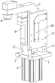
Fig. 1 is a schematic structural diagram of the present invention;
fig. 2 is a front view of the present invention;
fig. 3 isbase:Sub>A sectional view taken along linebase:Sub>A-base:Sub>A of the present invention.
Detailed Description
The following provides a more detailed description of the embodiments and the operation of the present invention with reference to the accompanying drawings.
As shown in fig. 1-3, a vertical positioning and pressing mechanism of a welding fixture includes a fixing plate 1, a thin cylinder 2 is fixed on a lower surface of the fixing plate 1, two guide blocks 3 are connected to an upper surface of the fixing plate 1 through support blocks 11, a connecting block 4 and a pressing arm 5 are arranged between the two guide blocks 3, a telescopic rod of the thin cylinder 2 penetrates the fixing plate 1 upwards and then is connected with the connecting block 4, two opposite limiting grooves 6 are further formed in the two guide blocks 3, a guide pin 7 is slidably limited in the limiting grooves 6, the connecting block 4 is connected with a lower end of the pressing arm 5 through the guide pin 7, a pressing head 8 is formed at an upper end of the pressing arm 5, and a vertical limiting block 9 is connected to a side of the guide block 3, which is close to the pressing head 8.
In this example, the supporting blocks 11 are disposed at both sides of the fixing plate 1, supporting steps are formed at both sides of the two supporting blocks 11, the guide block 3 is disposed above the supporting steps, and the installation of the guide block 3 is facilitated by the arrangement of the supporting steps.
Preferably, the limiting groove 6 is in an inverted L shape, and a dustproof baffle 10 is covered on the limiting groove 6, so that dust can enter the limiting groove to influence the movement of the guide pin 7; the pressing arm 5 is L-shaped, the vertical end of the pressing arm is downwards arranged and connected with the guide pin 7, and the bottom of the transverse end of the pressing arm is provided with the pressing head 8, so that the pressing arm 5 can rotate around the guide pin 7 to realize the lifting of the pressing head 8; the vertical limiting block 9 is in an inverted L shape, and the outer wall of the vertical part of the vertical limiting block is connected with the guide block 3.
This embodiment is when using, through the flexible of the slim cylinder 2 of control for the uide pin 7 is along 6 reciprocating motion of spacing groove, thereby drive pressure arm 5 rotates round uide pin 7, and then drive ram 8 reciprocates, and carries out the cooperation of vertical location through perpendicular stopper 9 under, realizes treating compressing tightly or the release of processing work piece. That is, through the arrangement of the structures such as the guide block 3, the guide pin 7, the limit groove 6 and the like, the movement track of the connection pressure head 8 of the thin cylinder 2 is limited to improve the stability of part positioning, and the smooth opening of the connection positioning mechanism of the cylinder 2 is ensured.
The technical scheme provided by the utility model is introduced in detail above. The principles and embodiments of the present invention have been explained herein using specific examples, and the above descriptions of the embodiments are only used to help understand the method and its core ideas of the present invention. It should be noted that, for those skilled in the art, without departing from the principle of the present invention, the present invention can be further modified and modified, and such modifications and modifications also fall within the protection scope of the appended claims.
Claims (5)
1. The utility model provides a welding jig's vertical location hold-down mechanism which characterized in that: including the fixed plate, be fixed with slim cylinder at the lower fixed surface of this fixed plate the upper surface of fixed plate is connected with two guide blocks through the supporting shoe, is provided with connecting block and pressure arm between two guide blocks, the telescopic link of slim cylinder upwards passes behind the fixed plate to be connected with this connecting block, has still seted up relative spacing groove on two guide blocks slide spacing in the spacing groove and have the uide pin, the connecting block pass through the uide pin with the lower extreme of pressing the arm is connected, the upper end of pressing the arm is formed with the pressure head the guide block is close to be connected with perpendicular stopper on pressure head one side.
2. The vertical positioning pressing mechanism of the welding jig of claim 1, characterized in that: the supporting blocks are arranged on two sides of the fixing plate, supporting steps are formed on two sides of the two supporting blocks, and the guide block is arranged above the supporting steps.
3. The vertical positioning pressing mechanism of the welding jig according to claim 1, characterized in that: the limiting groove is inverted L-shaped, and a dustproof baffle is covered on the limiting groove.
4. The vertical positioning pressing mechanism of the welding jig according to claim 1, characterized in that: the pressure arm is L-shaped, the vertical end of the pressure arm is arranged downwards and connected with the guide pin, and the bottom of the transverse end of the pressure arm is provided with the pressure head.
5. The vertical positioning pressing mechanism of the welding jig according to claim 1, characterized in that: the vertical limiting block is in an inverted L shape, and the outer wall of the vertical part of the vertical limiting block is connected with the guide block.
Priority Applications (1)
| Application Number | Priority Date | Filing Date | Title |
|---|---|---|---|
| CN202221357378.3U CN217571583U (en) | 2022-06-01 | 2022-06-01 | Vertical positioning and pressing mechanism of welding fixture |
Applications Claiming Priority (1)
| Application Number | Priority Date | Filing Date | Title |
|---|---|---|---|
| CN202221357378.3U CN217571583U (en) | 2022-06-01 | 2022-06-01 | Vertical positioning and pressing mechanism of welding fixture |
Publications (1)
| Publication Number | Publication Date |
|---|---|
| CN217571583U true CN217571583U (en) | 2022-10-14 |
Family
ID=83527565
Family Applications (1)
| Application Number | Title | Priority Date | Filing Date |
|---|---|---|---|
| CN202221357378.3U Active CN217571583U (en) | 2022-06-01 | 2022-06-01 | Vertical positioning and pressing mechanism of welding fixture |
Country Status (1)
| Country | Link |
|---|---|
| CN (1) | CN217571583U (en) |
-
2022
- 2022-06-01 CN CN202221357378.3U patent/CN217571583U/en active Active
Similar Documents
| Publication | Publication Date | Title |
|---|---|---|
| CN107971676B (en) | A kind of weld clamp method of automotive suspension control arm | |
| CN210649656U (en) | Hydraulic clamp with application force balanced positioning | |
| CN201012426Y (en) | Butt welding machine | |
| CN217571583U (en) | Vertical positioning and pressing mechanism of welding fixture | |
| CN211028869U (en) | Clamp for pulling small compressor plug | |
| CN102950413B (en) | A kind of pneumatic wedge shape slider pressing device | |
| CN217395145U (en) | Finished product discharge structure of cell-phone shell processing equipment | |
| CN214518971U (en) | Machine external clamp anchor clamps | |
| CN210388907U (en) | Positioning jig mechanism of assembling equipment | |
| CN212146144U (en) | A closing device for tool to lock assembly | |
| CN211465606U (en) | Mechanical equipment processing assembly platform | |
| CN211803255U (en) | Automobile door frame inner and outer plate edge covering device | |
| CN213614366U (en) | Automatic hole milling device of door plant | |
| CN208342694U (en) | A kind of lifter pre-pressing tooling | |
| CN208555761U (en) | It is a kind of with the metal plate placement positioning frame for automatically grabbing discharge mechanism | |
| CN203063267U (en) | Needling mechanical arm for shoe material gold stamping machine | |
| CN207289554U (en) | A kind of steel ball slidingtype hold-down mechanism | |
| CN206296366U (en) | A kind of stamping mold flanging and restriking mechanism | |
| CN213702455U (en) | Assembly tool for heightening sleeve | |
| CN201264319Y (en) | Device for automatically compacting machined workpiece | |
| CN215697254U (en) | Hydraulic punching device for producing hardware | |
| CN111715773B (en) | Punching equipment for machining computer case | |
| CN213972258U (en) | Material taking device for water pressing port | |
| CN211413413U (en) | Feeding device of bending machine | |
| CN221362053U (en) | Multifunctional bending die replacing device and bending machine |
Legal Events
| Date | Code | Title | Description |
|---|---|---|---|
| GR01 | Patent grant | ||
| GR01 | Patent grant |