CN217543506U - Digital display height prism rod - Google Patents
Digital display height prism rod Download PDFInfo
- Publication number
- CN217543506U CN217543506U CN202221426387.3U CN202221426387U CN217543506U CN 217543506 U CN217543506 U CN 217543506U CN 202221426387 U CN202221426387 U CN 202221426387U CN 217543506 U CN217543506 U CN 217543506U
- Authority
- CN
- China
- Prior art keywords
- prism
- support
- rod
- nut
- pole
- Prior art date
- Legal status (The legal status is an assumption and is not a legal conclusion. Google has not performed a legal analysis and makes no representation as to the accuracy of the status listed.)
- Active
Links
- 230000005611 electricity Effects 0.000 claims abstract description 4
- 238000009434 installation Methods 0.000 claims description 4
- 230000001105 regulatory effect Effects 0.000 abstract description 12
- 230000008901 benefit Effects 0.000 abstract description 3
- 239000011111 cardboard Substances 0.000 description 5
- 238000005259 measurement Methods 0.000 description 5
- 238000000034 method Methods 0.000 description 4
- 230000008569 process Effects 0.000 description 3
- 230000008859 change Effects 0.000 description 2
- 230000006835 compression Effects 0.000 description 2
- 238000007906 compression Methods 0.000 description 2
- 210000001503 joint Anatomy 0.000 description 2
- 238000012545 processing Methods 0.000 description 2
- 206010044565 Tremor Diseases 0.000 description 1
- 230000009471 action Effects 0.000 description 1
- 230000009286 beneficial effect Effects 0.000 description 1
- 230000005540 biological transmission Effects 0.000 description 1
- 238000000151 deposition Methods 0.000 description 1
- 238000011161 development Methods 0.000 description 1
- 230000000694 effects Effects 0.000 description 1
- 238000003780 insertion Methods 0.000 description 1
- 230000037431 insertion Effects 0.000 description 1
- 238000012986 modification Methods 0.000 description 1
- 230000004048 modification Effects 0.000 description 1
- 238000006467 substitution reaction Methods 0.000 description 1
Images


Landscapes
- A Measuring Device Byusing Mechanical Method (AREA)
Abstract
The application discloses digital display height's prism pole, including support and prism subassembly, be equipped with the regulating part between support and the prism subassembly, the regulating part includes alignment jig and regulation pole, adjusts the pole and rotates with the alignment jig to be connected, and the regulating part still includes first nut, first nut and regulation pole threaded connection, alignment jig and support fixed connection, adjust pole and prism subassembly fixed connection, are equipped with distancer and display screen on the regulating part. Through adopting above-mentioned technical scheme, when the prism subassembly inclines, adjust the pole through rotating, so that the prism subassembly on the regulating part is the horizontality, screw first nut, will adjust the pole through the frictional force between first nut and the alignment jig and fix to target inclination, the distancer is used for measuring the vertical height of support, and show highly with digital form on the display screen through the electricity connection, so that the vertical height of running point personnel reading support, this kind of measuring mode has high accuracy, easy advantage of operation.
Description
Technical Field
The application relates to the field of geological exploration, in particular to a prism rod with a digital display height.
Background
Along with the development of society, the technique that geological exploration used is more and more mature, measured data is also more and more accurate, total powerstation and prism pole are used widely as the range finding instrument, the prism pole is used for the light that the total powerstation sent, in the range finding process, need the observation personnel of a member cooperation operation total powerstation to run the point, run the point personnel and need fix the prism pole, then measure the height of prism pole, report the height of prism to the observation personnel, it is especially important in the range finding process to measure the height of prism, current prism pole adopts the ruler to measure the height of prism, there is the inconvenient problem of reading the height of prism, now provide a digital display height's prism pole.
SUMMERY OF THE UTILITY MODEL
In order to facilitate the measurement of the height of the reflecting prism, the present application provides a prism rod with a digital display of height.
The application provides a prism pole of digital display height adopts following technical scheme:
the utility model provides a prism pole of digital display height, includes support and prism subassembly, be equipped with the regulating part that is used for adjusting prism subassembly inclination between support and the prism subassembly, the regulating part includes alignment jig and regulation pole, adjust the pole with the alignment jig rotates to be connected, the regulating part still includes first nut, first nut with adjust pole threaded connection, alignment jig and support fixed connection, adjust the pole with prism subassembly fixed connection, fixed mounting has the display screen that is used for distancer and digital display height of measurement on the regulating part.
Through adopting above-mentioned technical scheme, the support plays and supports the fixed action, adjust the rotation of pole relative alignment jig, when prism subassembly slope, adjust the pole through rotating, so that the prism subassembly on the adjusting part is the horizontality, treat that the gradient adjustment of adjusting the pole finishes, the first nut of screwing, will adjust the pole through the frictional force between first nut and the alignment jig and fix target inclination, prism subassembly includes distancer and display screen, the distancer is used for measuring the vertical height of support, and show highly with digital form on the display screen through the electricity connection, in order to make things convenient for the vertical height that the point personnel of running read the support, this kind of measurement has high accuracy, the advantage of easy operation.
Optionally, the support includes a centering rod and at least two diagonal braces, the centering rod faces the point to be measured, a connecting plate is fixedly mounted on the centering rod, and the diagonal braces are rotatably connected with the connecting plate.
Through adopting above-mentioned technical scheme, the centering rod is used for the location to wait to measure the point, uses the cooperation centering rod support of diagonal brace pole fixed, replaces running some personnel's manual work to support the centering rod, reduces to tremble because of running some personnel and leads to measuring inaccurate condition emergence.
Optionally, the retaining member includes the locking seat, the locking seat with support fixed connection, the locking hole has been seted up on the locking seat, the retaining member still includes check lock lever and locking spring, the check lock lever wear to locate in the locking hole and with locking seat sliding connection, fixedly connected with latch segment on the check lock lever, the check lock lever passes locking spring, locking spring's both ends respectively with latch segment and locking seat butt.
Through adopting above-mentioned technical scheme, the retaining member is used for linking bridge and alignment jig, and the check lock lever can outwards be pulled out to drive the latch segment and outwards slide, reach support and alignment jig detachable purpose, have the advantage of convenient change, transport and depositing.
Optionally, a connecting pipe is arranged at the center of the connecting part of the plurality of adjusting frames, the connecting pipe is inserted into the support, a clamping groove is formed in the position, right opposite to the locking block, of the connecting pipe, and the locking block is in sliding connection with the clamping groove.
Through adopting above-mentioned technical scheme, the connecting pipe inserts in the latch seat, promote connecting pipe to connecting pipe and latch segment butt, continue to promote the connecting pipe, the outside latch segment that extrudees of connecting pipe, locking spring is in compression state this moment, when the draw-in groove just to the latch segment, the latch segment under the locking spring's that is in compression state promotion with the draw-in groove joint, thereby be connected fixedly with support and alignment jig, during the dismantlement, outwards stimulate the check lock lever to break away from in the draw-in groove to the latch segment, can take out the alignment jig.
Optionally, the adjusting part comprises a mounting plate, and the mounting plate is fixedly connected with the adjusting rod.
Through adopting above-mentioned technical scheme, the mounting panel is used for installing the fixed prism subassembly.
Optionally, the prism subassembly includes the prism frame, prism frame fixed mounting installs reflection prism on the mounting panel on the prism frame, reflection prism with be equipped with the connecting rod that is used for fixed reflection prism between the prism frame, the connecting rod passes the prism frame and with the prism frame rotates to be connected, connecting rod and reflection prism fixed connection.
Through adopting above-mentioned technical scheme, through the rotating connecting rod, drive reflection prism upset to realize reflection prism's angle modulation.
Optionally, one end of the connecting rod, which is far away from the prism frame, is provided with a second nut, the second nut is in threaded connection with the connecting rod, and the second nut is screwed inwards to be abutted against the prism frame, so that the reflecting prism is locked.
By adopting the technical scheme, when the inclination angle of the reflecting prism is adjusted, the second nut is screwed until the second nut is tightly abutted against the prism frame, so that the reflecting prism can be fixed.
Optionally, be equipped with the through-hole on the face at mounting panel edge, the mounting panel rotates in the edge of through-hole and installs the mount pad, the one end that the mount pad is close to reflection prism is equipped with the butt joint board, the distancer with display screen fixed mounting in on the mount pad, the distancer with the display screen electricity is connected.
Through adopting above-mentioned technical scheme, the through-hole is used for placing distancer and display screen, when needs range finding, outwards overturn the mount pad to fixed with the mounting panel butt, the detecting head of distancer is just to ground this moment, the vertical height information transmission of the support that the distancer will measure is to the display screen on to digital display's mode presents, conveniently reads data, only need when the use is accomplished to place the mount pad in the through-hole with the inside upset of mount pad to butt joint board and mounting panel butt.
In summary, the present application has the following beneficial effects: through retaining member linking bridge and regulating part, convenient change, dismantle and transport alignment jig, the mounting panel with adjust pole fixed connection, it rotates to drive the mounting panel through rotating the regulation pole, adjust the mounting panel through this kind of mode that does not have spacing angle modulation, make the mounting panel be in the horizontality, have very high maneuverability, and simple structure, set distancer and display screen to the structure of 180 degrees upsets, can realize the vertical height of high accuracy measurement support, can also regain distancer and display screen, save space, play the effect of protection distancer and display screen.
Drawings
Fig. 1 is a schematic view of a structure of a prism rod with a digital display height.
Fig. 2 is an enlarged view of a portion a in fig. 1.
Fig. 3 is a cross-sectional view of the retaining member.
Description of reference numerals:
1. a support; 11. a centering rod; 12. a diagonal brace; 13. a connecting plate; 2. an adjustment member; 21. an adjusting bracket; 211. mounting grooves; 212. a connecting pipe; 22. adjusting a rod; 23. a first nut; 24. mounting a plate; 3. a prism assembly; 31. a range finder; 32. a display screen; 33. a prism frame; 34. a reflective prism; 35. a connecting rod; 36. a second nut; 37. a mounting seat; 38. abutting against the plate; 39. a circular rod; 4. a locking member; 41. a locking seat; 42. a locking lever; 43. a locking spring; 44. and a locking block.
Detailed Description
The present application is described in further detail below with reference to figures 1-3.
The embodiment of the application discloses a prism pole of digital display height, refer to fig. 1-2, including support 1 and prism subassembly 3, support 1 is used for supporting prism subassembly 3, is equipped with the regulating part 2 that is used for adjusting prism subassembly 3's angle between support 1 and the prism subassembly 3, and regulating part 2 and support 1 joint.
Referring to fig. 1, the support 1 includes a centering rod 11 and two diagonal braces 12, the centering rod 11 is vertically disposed, one end of the centering rod 11, which is far away from the ground, is fixedly connected with a connecting plate 13, the connecting plate 13 is a circular plate and is horizontally disposed, the centering rod 11 is located at a central position of a bottom surface of the connecting plate 13, one ends of the two diagonal braces 12 are both located at an arc surface of the connecting plate 13 and are hinged to the connecting plate 13, one ends of the diagonal braces 12, which are close to the ground, can be outwardly unfolded, the two diagonal braces 12 are both unfolded and are supported by the centering rod 11 in a triangular manner, so that the support 1 can be stably fixed on a point to be measured, the centering rod 11 and the two diagonal braces 12 are telescopic rods, and height adjustment of the prism rod can be achieved by telescopically adjusting the centering rod 11 and the two diagonal braces 12.
Referring to fig. 2, the adjusting member 2 includes an adjusting frame 21 and an adjusting rod 22, the adjusting frame 21 is a U-shaped frame, two ends of the adjusting frame 21 are each provided with an installation groove 211, two ends of the adjusting rod 22 are disposed in the installation grooves 211 and rotatably connected with the adjusting frame 21, a first nut 23 is located at one end of the adjusting rod 22 extending out of the adjusting frame 21, the first nut 23 is in threaded connection with the adjusting rod 22, when the first nut 23 is screwed in a direction close to the adjusting frame 21 and abuts against the adjusting frame 21, friction force is generated between the first nut 23 and the adjusting frame 21, so that the adjusting rod 22 and the adjusting frame 21 can be fixed, the adjusting member 2 further includes a mounting plate 24, the mounting plate 24 is fixedly connected with the adjusting rod 22, the mounting plate 24 is provided with a level gauge (not shown), an inclination angle of the mounting plate 24 can be adjusted by observing the level gauge and rotating the adjusting rod 22, so that the mounting plate 24 is in a horizontal state, and the mounting plate 24 can be locked by screwing the first nut 23.
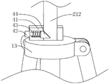
Referring to fig. 3, top surface fixed mounting of connecting plate 13 has retaining member 4, retaining member 4 includes locking seat 41 and locking lever 42, locking seat 41 and support 1 fixed connection, be equipped with the holding chamber in the locking seat 41, locking lever 42 wears to locate the holding intracavity from one side level of locking seat 41, the one end that locking lever 42 is located the holding intracavity is equipped with latch segment 44, latch segment 44 and locking lever 42 fixed connection, the one end that locking lever 42 was kept away from to latch segment 44 is inclined to the one end of keeping away from locking lever 42 by the one end that is close to locking lever 42, retaining member 4 still includes locking spring 43, locking spring 43 is located the holding intracavity, locking lever 42 wears to locate in locking spring 43, the both ends of locking spring 43 respectively with latch segment 44 and locking seat 41 butt.
Referring to fig. 2-3, a connecting pipe 212 is fixedly connected to a center position of the joint of the adjusting bracket 21, a slot (not shown in the figure) for the locking block 44 to enter is arranged at a position of the connecting pipe 212 facing the locking block 44, the locking block 44 is in insertion fit with the slot, the locking block 44 enters the slot under the pushing of the locking spring 43, the adjusting part 2 is fixedly connected with the bracket 1, and when the adjusting part 2 needs to be detached, the adjusting part 2 can be detached only by pulling the locking rod 42 outwards until the locking block 44 completely slides out of the slot.
Referring to fig. 2, the prism assembly 3 includes a prism frame 33 and a reflection prism 34, the prism frame 33 is welded with the mounting plate 24, the reflection prism 34 is mounted on the prism frame 33, a connecting rod 35 for fixing the reflection prism 34 is disposed between the reflection prism 34 and the prism frame 33, the connecting rod 35 passes through the prism frame 33 and is fixedly connected with the reflection prism 34, the connecting rod 35 is rotatably connected with the prism frame 33, a second nut 36 is disposed at one end of the connecting rod 35 extending out of the prism frame 33, the second nut 36 is in threaded connection with the connecting rod 35, the reflection prism 34 is rotated, the reflection prism 34 is adjusted to a target reflection direction, the second nut 36 is screwed to be tightly abutted against the prism frame 33, and the reflection prism 34 is fixed on the prism frame 33 through a friction force between the second nut 36 and the prism frame 33.
Referring to fig. 2, circular through-hole has been seted up along mounting panel 24 thickness direction on the face that mounting panel 24 is close to marginal portion, mounting panel 24 has circular rod 39 in the edge level of through-hole fixed, be equipped with mount pad 37 on the mounting panel 24, mount pad 37's one end and circular rod 39 rotate to be connected, mount pad 37 has two cardboards in pivot department fixed mounting, two cardboards and mounting panel 24 fixed connection, two cardboards distribute in the both ends of mount pad 37 with mounting panel 24's junction, outwards overturn to when being parallel with mounting panel 24 when mount pad 37, cardboard and mounting panel 24 butt, make mount pad 37 keep in same horizontality with mounting panel 24, the one end fixed mounting that mount pad 37 kept away from the cardboard has outside butt board 38 that extends, when mount pad 37 inwards rotates to circular through-hole, butt board 38 and mounting panel 24 butt.
Referring to fig. 2, a distance meter 31 and a display screen 32 are mounted on a mounting seat 37, both the distance meter 31 and the display screen 32 are fixedly mounted on the mounting seat 37, the distance meter 31 is electrically connected with the display screen 32, when the mounting seat 37 is turned outwards, a detecting head of the distance meter 31 is right opposite to the ground, the distance meter 31 is used for measuring the distance from a mounting plate 24 to the ground and transmitting the height information obtained by measurement to a digital processing module, and the digital processing module processes the height information and then displays the height information in a digital form on the display screen 32. When use is complete, the mounting seat 37 is turned inwardly until the abutment plate 38 abuts the mounting plate 24, at which point the mounting seat 37 is placed in the through hole.
The working principle of the digital display height prism rod is as follows: referring to fig. 1-3, the centering rod 11 is aligned to the point to be measured, the two inclined support rods 12 are opened, the prism rod is erected at the point to be measured, the height of the prism rod is adjusted to the target height, the connecting pipe 212 is inserted into the locking seat 41 to the locking block 44 and clamped with the connecting pipe 212, the adjusting rod 22 is adjusted while observing the level on the mounting plate 24, the mounting plate 24 is driven by the adjusting rod 22 to rotate until the mounting plate 24 is in the horizontal state, the first nut 23 is screwed until the mounting plate is tightly clamped and fixed with the side wall of the adjusting frame 21, the mounting seat 37 is opened, the mounting seat 37 is turned over and fixed outwards, the reflection prism 34 is adjusted until the reflection prism 34 reaches the target inclination angle, and the second nut 36 is screwed inwards until the reflection prism frame 33 is tightly abutted.
It should be clear to those skilled in the art that, for convenience and simplicity of description, the foregoing division of the functional units and modules is only used for illustration, and in practical applications, the above function distribution may be performed by different functional units and modules as needed, that is, the internal structure of the device is divided into different functional units or modules, so as to perform all or part of the above described functions.
The above examples are only intended to illustrate the technical solution of the present invention, but not to limit it; although the present invention has been described in detail with reference to the foregoing embodiments, it will be understood by those of ordinary skill in the art that: the technical solutions described in the foregoing embodiments may still be modified, or some technical features may be equivalently replaced; such modifications and substitutions do not depart from the spirit and scope of the embodiments of the present invention, and they should be construed as being included therein.
Claims (8)
1. A prism pole with digital display height, characterized in that: including support (1) and prism subassembly (3), be equipped with between support (1) and prism subassembly (3) and be used for adjusting adjustment piece (2) of prism subassembly (3) inclination, adjustment piece (2) are including alignment jig (21) and regulation pole (22), adjust pole (22) with alignment jig (21) rotate to be connected, alignment jig (2) still include first nut (23), first nut (23) with adjust pole (22) threaded connection, alignment jig (21) and support (1) fixed connection, adjust pole (22) with prism subassembly (3) fixed connection, fixed mounting is used for distancer (31) and the display screen (32) of digital display height on alignment jig (2).
2. A digital height indicating prism rod according to claim 1, wherein: the support comprises a centering rod (11) and at least two inclined supporting rods (12), the centering rod (11) is opposite to a point to be measured, a connecting plate (13) is fixedly installed on the centering rod (11), and the inclined supporting rods (12) are rotatably connected with the connecting plate (13).
3. A digital height indicating prism rod according to claim 1, wherein: one end that support (1) is close to alignment jig (21) is equipped with retaining member (4), retaining member (4) are including locking seat (41), locking seat (41) with support (1) fixed connection, the locking hole has been seted up on locking seat (41), retaining member (4) still include check lock lever (42) and locking spring (43), check lock lever (42) wear to locate in the locking hole and with locking seat (41) sliding connection, fixedly connected with latch segment (44) on check lock lever (42), locking spring (43) are passed to check lock lever (42), the both ends of locking spring (43) respectively with latch segment (44) and locking seat (41) butt.
4. A digital height indicating prism bar according to claim 3, wherein: the center position of the connecting part of a plurality of adjusting frames (21) is provided with a connecting pipe (212), the connecting pipe (212) is spliced with the support (1), the connecting pipe (212) is just opposite to the position of the locking block (44) is provided with a clamping groove, and the locking block (44) is in sliding connection with the clamping groove.
5. A digital height indicating prism bar according to claim 1, wherein: the adjusting piece (2) comprises an installation plate (24), and the installation plate (24) is fixedly connected with the adjusting rod (22).
6. A digital height indicating prism rod according to claim 5, wherein: prism subassembly (3) include prism frame (33), prism frame (33) fixed mounting installs reflecting prism (34) on mounting panel (24), on prism frame (33), reflecting prism (34) with be equipped with connecting rod (35) that are used for fixed reflecting prism (34) between prism frame (33), connecting rod (35) pass prism frame (33) and with prism frame (33) rotate and are connected, connecting rod (35) and reflecting prism (34) fixed connection.
7. A digital height indicating prism rod according to claim 6, wherein: the one end that prism frame (33) was kept away from in connecting rod (35) is equipped with second nut (36), second nut (36) with connecting rod (35) threaded connection will second nut (36) inwards screw to with prism frame (33) butt, realize locking reflection prism (34).
8. A digital height indicating prism bar according to claim 5, wherein: be equipped with the through-hole on the face at mounting panel (24) edge, mounting panel (24) rotate at the edge of through-hole and install mount pad (37), the one end that mount pad (37) are close to reflecting prism (34) is equipped with butt plate (38), distancer (31) with display screen (32) fixed mounting in on mount pad (37), distancer (31) with display screen (32) electricity is connected.
Priority Applications (1)
| Application Number | Priority Date | Filing Date | Title |
|---|---|---|---|
| CN202221426387.3U CN217543506U (en) | 2022-06-09 | 2022-06-09 | Digital display height prism rod |
Applications Claiming Priority (1)
| Application Number | Priority Date | Filing Date | Title |
|---|---|---|---|
| CN202221426387.3U CN217543506U (en) | 2022-06-09 | 2022-06-09 | Digital display height prism rod |
Publications (1)
| Publication Number | Publication Date |
|---|---|
| CN217543506U true CN217543506U (en) | 2022-10-04 |
Family
ID=83443317
Family Applications (1)
| Application Number | Title | Priority Date | Filing Date |
|---|---|---|---|
| CN202221426387.3U Active CN217543506U (en) | 2022-06-09 | 2022-06-09 | Digital display height prism rod |
Country Status (1)
| Country | Link |
|---|---|
| CN (1) | CN217543506U (en) |
-
2022
- 2022-06-09 CN CN202221426387.3U patent/CN217543506U/en active Active
Similar Documents
| Publication | Publication Date | Title |
|---|---|---|
| CN208254480U (en) | A kind of Multifunctional total station instrument | |
| CN217543506U (en) | Digital display height prism rod | |
| CN212960642U (en) | Visual inspection camera support | |
| KR101625728B1 (en) | Setting apparatus, as well as a magnetic resonance apparatus with a setting apparatus | |
| CN216383276U (en) | Level gauge for building detection settlement measurement | |
| CN216479785U (en) | Laser range finder fixed equipment for building engineering cost | |
| CN215177701U (en) | An auxiliary detection device for the installation of a roller assembly | |
| CN211853258U (en) | Surveying instrument for field engineering survey | |
| CN221222072U (en) | Balanced stabilizing mean of geological survey appearance | |
| CN213688248U (en) | Engineering of roughness detects uses measuring component | |
| CN210153487U (en) | Total powerstation convenient to installation with adjustment mechanism | |
| CN213657790U (en) | Reflection type centering instrument for keeping circle center of measured part unchanged | |
| CN215064323U (en) | Pigtail end face inspection equipment | |
| CN220980819U (en) | Level supporting device for engineering measurement | |
| CN211374484U (en) | Horizontal adjusting device of resolution meter | |
| CN212869192U (en) | Support convenient for leveling for constructional engineering level | |
| CN211373382U (en) | Measuring scale for highway civil construction detection with height easy to adjust | |
| CN113008199A (en) | Level gauge for engineering survey | |
| CN221351170U (en) | Online beam split type transmissivity detector | |
| CN221237462U (en) | Three-dimensional photogrammetry device convenient to use | |
| CN216480046U (en) | Forestry surveys with measuring auxiliary device | |
| CN220708373U (en) | Geological survey level gauge with good stability | |
| CN221630742U (en) | Surveying instrument with shading structure | |
| CN223425980U (en) | Laser marking device for measurement | |
| CN223880124U (en) | Ultra-high measurement unit adjusting device of railway track inspection tester |
Legal Events
| Date | Code | Title | Description |
|---|---|---|---|
| GR01 | Patent grant | ||
| GR01 | Patent grant |