CN217543456U - A kind of anti-loose mine fiber optic connector - Google Patents
A kind of anti-loose mine fiber optic connector Download PDFInfo
- Publication number
- CN217543456U CN217543456U CN202221630502.9U CN202221630502U CN217543456U CN 217543456 U CN217543456 U CN 217543456U CN 202221630502 U CN202221630502 U CN 202221630502U CN 217543456 U CN217543456 U CN 217543456U
- Authority
- CN
- China
- Prior art keywords
- connecting pipe
- optical fiber
- connector
- extrados
- spring
- Prior art date
- Legal status (The legal status is an assumption and is not a legal conclusion. Google has not performed a legal analysis and makes no representation as to the accuracy of the status listed.)
- Active
Links
Images


Landscapes
- Quick-Acting Or Multi-Walled Pipe Joints (AREA)
Abstract
本实用新型公开了一种防松动矿用光纤连接器,包括第一连接管和锁止机构;第一连接管:其外弧面上下两端分别设有卡槽板,第一连接管的右端摆放有第二连接管,第二连接管的外弧面上下两端分别设有卡槽,卡槽板均与左右对应的卡槽卡接,第一连接管右端的安装槽内部设有第一连接头,第一连接头的右端设有第一光纤,第二连接管左端的槽口内部设有第二连接头,第二连接头左端的插柱与第一连接头右端的插孔插接,第二连接头的右端设有第二光纤,该防松动矿用光纤连接器,使装置之间始终处于被锁止的状态,避免了装置在连接后出现松动的情况,对装置内部的光纤进行持续压紧,避免装置内部的光纤出现晃动的情况。
The utility model discloses an anti-loose mining optical fiber connector, which comprises a first connecting pipe and a locking mechanism; the first connecting pipe: the upper and lower ends of the outer arc surface are respectively provided with card slot plates, and the right end of the first connecting pipe is provided with a slot plate. A second connecting pipe is placed, the upper and lower ends of the outer arc of the second connecting pipe are respectively provided with card grooves, the card groove plates are all connected with the corresponding card grooves on the left and right, and the inside of the installation groove on the right end of the first connecting pipe is provided with a second connecting pipe. A connector, the right end of the first connector is provided with a first optical fiber, the slot at the left end of the second connector tube is provided with a second connector, and the plug on the left end of the second connector is inserted into the jack on the right end of the first connector The right end of the second connector is provided with a second optical fiber. The anti-loose mining fiber optic connector keeps the devices in a locked state all the time, avoiding the looseness of the device after the connection. The optical fiber is continuously compressed to avoid shaking of the optical fiber inside the device.
Description
技术领域technical field
本实用新型涉及光纤连接器技术领域,具体为一种防松动矿用光纤连接器。The utility model relates to the technical field of optical fiber connectors, in particular to an anti-loose mining optical fiber connector.
背景技术Background technique
光纤连接器,是光纤与光纤之间进行可拆卸连接的器件,光纤连接器的主要用途是用以实现光纤的接续,广泛应用在光纤通信系统中,光纤连接器的基本结构却是一致的,大多数的光纤连接器的一般采用高精密组件来实现光纤的对准连接,在矿产作业中,光纤连接器易被外部物体碰撞拉扯,导致光纤连接器内部的光纤连接处产生松动,情况严重时还会导致光纤连接器内部的光纤连接处发生脱落的情况,如果人员没有及时发现,就会导致工作设备的停机,影响作业进度,为此,我们提出一种防松动矿用光纤连接器来解决这些问题。Optical fiber connector is a device for detachable connection between optical fibers and optical fibers. The main purpose of optical fiber connectors is to realize the connection of optical fibers. It is widely used in optical fiber communication systems. The basic structure of optical fiber connectors is the same. Most of the optical fiber connectors generally use high-precision components to realize the alignment and connection of the optical fibers. In mining operations, the optical fiber connectors are easily pulled by external objects, resulting in loosening of the optical fiber connections inside the optical fiber connectors. It will also cause the optical fiber connection inside the optical fiber connector to fall off. If the personnel does not find it in time, it will lead to the shutdown of the working equipment and affect the operation progress. Therefore, we propose an anti-loose mine fiber optic connector to solve the problem. these questions.
实用新型内容Utility model content
本实用新型要解决的技术问题是克服现有的缺陷,提供一种防松动矿用光纤连接器,使装置之间始终处于被锁止的状态,避免了装置在连接后出现松动的情况,工作时可对装置内部的光纤进行持续压紧,避免装置内部的光纤出现晃动的情况,减少了光纤与接线端脱落的发生,可以有效解决背景技术中的问题。The technical problem to be solved by the utility model is to overcome the existing defects and provide an anti-loose mining optical fiber connector, so that the devices are always in a locked state, avoiding the looseness of the devices after the connection, and the work The optical fiber inside the device can be continuously compressed at the same time to avoid the shaking of the optical fiber inside the device, reduce the occurrence of the optical fiber and the terminal falling off, and can effectively solve the problems in the background technology.
为实现上述目的,本实用新型提供如下技术方案:一种防松动矿用光纤连接器,包括第一连接管和锁止机构;In order to achieve the above purpose, the present utility model provides the following technical solutions: an anti-loose mining optical fiber connector, comprising a first connecting tube and a locking mechanism;
第一连接管:其外弧面上下两端分别设有卡槽板,第一连接管的右端摆放有第二连接管,第二连接管的外弧面上下两端分别设有卡槽,卡槽板均与左右对应的卡槽卡接,第一连接管右端的安装槽内部设有第一连接头,第一连接头的右端设有第一光纤,第二连接管左端的槽口内部设有第二连接头,第二连接头左端的插柱与第一连接头右端的插孔插接,第二连接头的右端设有第二光纤;The first connecting pipe: the upper and lower ends of the outer arc surface are respectively provided with card slot plates, the right end of the first connecting pipe is placed with a second connecting pipe, and the upper and lower ends of the outer arc surface of the second connecting pipe are respectively provided with card grooves. The card slot plates are all connected with the corresponding card slots on the left and right, a first connector is arranged inside the installation slot on the right end of the first connecting tube, a first optical fiber is arranged on the right end of the first connector, and the slot on the left end of the second connecting tube is inside A second connector is provided, the left end of the second connector is inserted into the socket on the right end of the first connector, and the right end of the second connector is provided with a second optical fiber;
锁止机构:设置于第二连接管外弧面的开槽内部,使装置之间始终处于被锁止的状态,避免了装置在连接后出现松动的情况,提高了装置连接处的紧密性,对装置内部的光纤进行持续压紧,避免装置内部的光纤出现晃动的情况,减少了光纤与接线端脱落的情况。Locking mechanism: It is arranged inside the slot of the outer arc surface of the second connecting pipe, so that the devices are always in a locked state, which avoids the loosening of the devices after the connection, and improves the tightness of the connection of the devices. The optical fiber inside the device is continuously compressed to avoid shaking of the optical fiber inside the device and reduce the falling off of the optical fiber and the terminal.
进一步的,所述锁止机构包括滑槽和齿牙板,所述滑槽分别开设于第一连接管的外弧面前后两端右侧,第二连接管外弧面前后两端的开槽内部分别设有齿牙板,齿牙板均与滑槽滑动连接,方便装置之间的连接。Further, the locking mechanism includes a chute and a tooth plate, the chute is respectively opened on the right side of the front and rear ends of the outer arc of the first connecting pipe, and the inside of the slot on the front and rear ends of the outer arc of the second connecting pipe. The tooth plates are respectively provided, and the tooth plates are all slidably connected with the chute to facilitate the connection between the devices.
进一步的,所述锁止机构还包括固定台、柱体、齿条板和把手,所述固定台分别设置于第一连接管的外弧面前后两端右侧,柱体分别对称滑动连接于固定台的孔口内部,齿条板分别设置于左右对应的两个柱体靠近第一连接管中心的一端,齿条板均与齿牙板配合安装,把手分别设置于左右对应的两个柱体远离第一连接管中心的一端,实现装置之间的快速锁止固定。Further, the locking mechanism further includes a fixing table, a cylinder, a rack plate and a handle, the fixing platforms are respectively arranged on the right side of the front and rear ends of the outer arc of the first connecting pipe, and the cylinders are respectively symmetrically slidably connected to the Inside the orifice of the fixing table, the rack plates are respectively arranged at one end of the left and right corresponding column bodies close to the center of the first connecting pipe, the rack plates are installed in cooperation with the tooth plate, and the handles are respectively arranged on the left and right corresponding two columns One end of the body away from the center of the first connecting pipe realizes quick locking and fixing between devices.
进一步的,所述锁止机构还包括第一弹簧,所述第一弹簧均套设于柱体的外弧面,四个第一弹簧的相对内侧端均与前后相邻的齿条板固定连接,四个第一弹簧远离第一连接柱中心的一端均与前后对应的固定台固定连接,使装置始终处于被锁止状态。Further, the locking mechanism further includes a first spring, the first springs are all sleeved on the outer arc surface of the cylinder, and the opposite inner ends of the four first springs are fixedly connected to the front and rear adjacent rack plates. , one end of the four first springs away from the center of the first connecting column is fixedly connected with the front and rear corresponding fixing platforms, so that the device is always in a locked state.
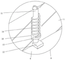
进一步的,还包括滑孔、滑柱和弧形板,所述滑孔分别开设于第一连接管和第二连接管的外弧面上端,滑柱均滑动连接于滑孔的内部,弧形板均设置于滑柱的下端,左端的弧形板下端与第一光纤的外弧面上端接触,右端的弧形板下端与第二光纤的外弧面上端接触,对光纤进行快速压紧。Further, it also includes a sliding hole, a sliding column and an arc-shaped plate. The sliding hole is respectively opened on the upper end of the outer arc surface of the first connecting pipe and the second connecting pipe, and the sliding column is slidably connected to the inside of the sliding hole. The plates are all arranged at the lower end of the spool, the lower end of the arc plate at the left end is in contact with the upper end of the outer arc of the first optical fiber, and the lower end of the arc plate at the right end is in contact with the upper end of the outer arc of the second optical fiber to quickly compress the optical fiber.
进一步的,还包括固定环和第二弹簧,所述固定环均固定套接于滑柱的外弧面下端,第二弹簧均套设于滑柱的外弧面,第二弹簧的上端均与同侧的滑孔内部上端固定连接,第二弹簧的下端均与上下对应的固定环上侧固定连接,实现对光纤的持续压紧。Further, it also includes a fixing ring and a second spring, the fixing rings are fixedly sleeved on the lower end of the outer arc surface of the sliding column, the second springs are all sleeved on the outer arc surface of the sliding column, and the upper ends of the second springs are all sleeved with the outer arc surface of the sliding column. The inner upper ends of the sliding holes on the same side are fixedly connected, and the lower ends of the second springs are fixedly connected with the upper sides of the upper and lower corresponding fixing rings, so as to realize continuous compression of the optical fiber.
进一步的,还包括密封条,所述密封条设置于第一连接管右端的圆环槽内部,密封条的右端与第二连接管的左端接触,提高了装置之间的气密性。Further, it also includes a sealing strip, the sealing strip is arranged inside the annular groove at the right end of the first connecting pipe, and the right end of the sealing strip is in contact with the left end of the second connecting pipe, which improves the air tightness between the devices.
与现有技术相比,本实用新型的有益效果是:本防松动矿用光纤连接器,具有以下好处:Compared with the prior art, the beneficial effects of the present utility model are: the anti-loose mine optical fiber connector has the following advantages:
1、人员首先手握把手向相反向进行拉动,把手带动柱体运动,柱体带动齿条板向远离第一连接管的方向移动,齿条板压缩第一弹簧,第一弹簧处于收缩状态,然后人员将第一连接管和第二连接管对应放置并相向靠近,使卡槽板卡接入卡槽的内部,这时第一连接头右端的插孔与第二连接头左端的插柱插接,完成第一光纤和第二光纤的对接,与此同时,齿牙板滑入滑槽的内部,人员脱离对把手的控制,第一弹簧释放的张力推动齿条板运动,齿条板在柱体的导向支撑作用下向靠近第一连接管的方向进行移动,直至齿条板与齿牙板配合安装,始终使齿条板与齿牙板处于啮合状态,使装置之间始终处于被锁止的状态,避免了装置在连接后出现松动的情况,提高了装置连接处的紧密性。1. First, the person pulls the handle in the opposite direction, the handle drives the cylinder to move, the cylinder drives the rack plate to move away from the first connecting pipe, the rack plate compresses the first spring, and the first spring is in a contracted state. Then personnel place the first connecting pipe and the second connecting pipe correspondingly and approach each other, so that the card slot board is inserted into the inside of the card slot. The connection between the first optical fiber and the second optical fiber is completed. At the same time, the toothed plate slides into the inside of the chute, and the personnel are released from the control of the handle. The tension released by the first spring pushes the rack plate to move, and the rack plate is in Under the guiding and supporting action of the cylinder, it moves toward the direction close to the first connecting pipe until the rack plate and the tooth plate are installed together, so that the rack plate and the tooth plate are always in meshing state, so that the devices are always locked. It can prevent the device from loosening after being connected, and improve the tightness of the connection of the device.
2、工作期间第二弹簧释放的张力推动固定环向下侧移动,固定环带动滑柱在滑孔的内部向下侧滑动,左侧的滑柱带动弧形板压紧第一光纤的外弧面上端,右侧的滑柱带动弧形板压紧第二光纤的外弧面上端,对装置内部的光纤进行持续压紧,避免装置内部的光纤出现晃动的情况,减少了光纤与接线端脱落的情况。2. During operation, the tension released by the second spring pushes the fixing ring to move downward, the fixing ring drives the sliding column to slide downwards inside the sliding hole, and the sliding column on the left drives the arc plate to compress the outer arc of the first optical fiber. On the upper side, the sliding column on the right side drives the arc plate to press the outer arc surface of the second optical fiber, and continuously compresses the optical fiber inside the device, so as to avoid the optical fiber inside the device from shaking, and reduce the loss of the optical fiber and the terminal. Case.
附图说明Description of drawings
图1为本实用新型结构示意图;Fig. 1 is the structural representation of the utility model;
图2为本实用新型剖视结构示意图;Fig. 2 is the sectional structure schematic diagram of the utility model;
图3为本实用新型A处放大结构示意图;Fig. 3 is the enlarged structural schematic diagram of the utility model A;
图4为本实用新型B处放大结构示意图。FIG. 4 is a schematic view of the enlarged structure at B of the present invention.
图中:1第一连接管、2卡槽板、3第二连接管、4卡槽、5第一连接头、6第一光纤、7第二连接头、8第二光纤、9锁止机构、91滑槽、92齿牙板、93固定台、94柱体、95齿条板、96把手、97第一弹簧、10滑孔、11滑柱、12弧形板、13固定环、14第二弹簧、15密封条。In the figure: 1 first connecting pipe, 2 card slot plate, 3 second connecting pipe, 4 card groove, 5 first connector, 6 first optical fiber, 7 second connector, 8 second optical fiber, 9 locking mechanism , 91 chute, 92 tooth plate, 93 fixed table, 94 cylinder, 95 rack plate, 96 handle, 97 first spring, 10 sliding hole, 11 sliding column, 12 arc plate, 13 fixing ring, 14 first spring Two springs, 15 sealing strips.
具体实施方式Detailed ways
下面将结合本实用新型实施例中的附图,对本实用新型实施例中的技术方案进行清楚、完整地描述,显然,所描述的实施例仅仅是本实用新型一部分实施例,而不是全部的实施例。基于本实用新型中的实施例,本领域普通技术人员在没有做出创造性劳动前提下所获得的所有其他实施例,都属于本实用新型保护的范围。The technical solutions in the embodiments of the present utility model will be clearly and completely described below with reference to the accompanying drawings in the embodiments of the present utility model. Obviously, the described embodiments are only a part of the embodiments of the present utility model, rather than all the implementations. example. Based on the embodiments of the present invention, all other embodiments obtained by those of ordinary skill in the art without creative work fall within the protection scope of the present invention.
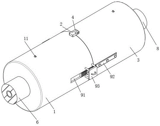
请参阅图1-4,本实施例提供一种技术方案:一种防松动矿用光纤连接器,包括第一连接管1和锁止机构9;Referring to FIGS. 1-4 , this embodiment provides a technical solution: an anti-loose mining optical fiber connector, comprising a first connecting tube 1 and a locking mechanism 9 ;
第一连接管1:其外弧面上下两端分别设有卡槽板2,第一连接管1的右端摆放有第二连接管3,第二连接管3的外弧面上下两端分别设有卡槽4,卡槽板2和卡槽4实现对第一连接管1和第二连接管3的固定作用,卡槽板2均与左右对应的卡槽4卡接,第一连接管1右端的安装槽内部设有第一连接头5,第一连接头5实现与第一光纤6的连接作用,第一连接头5的右端设有第一光纤6,第二连接管3左端的槽口内部设有第二连接头7,第二连接头7实现对第二光纤8的连接作用,第二连接头7左端的插柱与第一连接头5右端的插孔插接,第二连接头7的右端设有第二光纤8;The first connecting pipe 1: the upper and lower ends of the outer arc surface are respectively provided with
锁止机构9:设置于第二连接管3外弧面的开槽内部,锁止机构9包括滑槽91和齿牙板92,滑槽91分别开设于第一连接管1的外弧面前后两端右侧,第二连接管3外弧面前后两端的开槽内部分别设有齿牙板92,齿牙板92均与滑槽91滑动连接,锁止机构9还包括固定台93、柱体94、齿条板95和把手96,固定台93分别设置于第一连接管1的外弧面前后两端右侧,柱体94分别对称滑动连接于固定台93的孔口内部,齿条板95分别设置于左右对应的两个柱体94靠近第一连接管1中心的一端,齿条板95均与齿牙板92配合安装,把手96分别设置于左右对应的两个柱体94远离第一连接管1中心的一端,锁止机构9还包括第一弹簧97,第一弹簧97均套设于柱体94的外弧面,四个第一弹簧97的相对内侧端均与前后相邻的齿条板95固定连接,四个第一弹簧97远离第一连接柱1中心的一端均与前后对应的固定台93固定连接,人员首先手握把手96向相反向进行拉动,把手96带动柱体94运动,柱体94带动齿条板95向远离第一连接管1的方向移动,齿条板95压缩第一弹簧97,第一弹簧97处于收缩状态,当第一连接管1与第二连接管3对接后,齿牙板92滑入滑槽91的内部,人员脱离对把手96的控制,第一弹簧97释放的张力推动齿条板95运动,齿条板95在柱体94的导向支撑作用下向靠近第一连接管1的方向进行移动,直至齿条板95与齿牙板92配合安装,始终使齿条板95与齿牙板92处于啮合状态,使装置之间始终处于被锁止的状态,避免了装置在连接后出现松动的情况;Locking mechanism 9 : set inside the slot of the outer arc surface of the second connecting
其中:还包括滑孔10、滑柱11和弧形板12,滑孔10分别开设于第一连接管1和第二连接管3的外弧面上端,滑孔10实现滑柱11的安装作用,滑柱11均滑动连接于滑孔10的内部,滑柱11实现对弧形板12的连接作用,弧形板12均设置于滑柱11的下端,弧形板12实现对光纤的压紧作用,左端的弧形板12下端与第一光纤6的外弧面上端接触,右端的弧形板12下端与第二光纤6的外弧面上端接触。Among them: it also includes a sliding
其中:还包括固定环13和第二弹簧14,固定环13均固定套接于滑柱11的外弧面下端,第二弹簧14均套设于滑柱11的外弧面,第二弹簧14的上端均与同侧的滑孔10内部上端固定连接,第二弹簧14的下端均与上下对应的固定环13上侧固定连接,工作期间第二弹簧14释放的张力推动固定环13向下侧移动,固定环13带动滑柱11在滑孔10的内部向下侧滑动,左侧的滑柱11带动弧形板12压紧第一光纤6的外弧面上端,右侧的滑柱11带动弧形板12压紧第二光纤8的外弧面上端,避免装置内部的光纤出现晃动的情况。Wherein: it also includes a fixing
其中:还包括密封条15,密封条15设置于第一连接管1右端的圆环槽内部,密封条15提高了第一连接管1和第二连接管3连接处的气密性,密封条15的右端与第二连接管3的左端接触。Wherein: it also includes a sealing
本实用新型提供的一种防松动矿用光纤连接器的工作原理如下:人员首先手握把手96向相反向进行拉动,把手96带动柱体94运动,柱体94带动齿条板95向远离第一连接管1的方向移动,齿条板95压缩第一弹簧97,第一弹簧97处于收缩状态,然后人员将第一连接管1和第二连接管3对应放置并相向靠近,使卡槽板2卡接入卡槽4的内部,这时第一连接头5右端的插孔与第二连接头7左端的插柱插接,完成第一光纤6和第二光纤8的对接,与此同时,齿牙板92滑入滑槽91的内部,人员脱离对把手96的控制,第一弹簧97释放的张力推动齿条板95运动,齿条板95在柱体94的导向支撑作用下向靠近第一连接管1的方向进行移动,直至齿条板95与齿牙板92配合安装,始终使齿条板95与齿牙板92处于啮合状态,实现对第一连接管1和第二连接管3的锁止固定,避免装置连接后出现松动的情况,工作期间第二弹簧14释放的张力推动固定环13向下侧移动,固定环13带动滑柱11在滑孔10的内部向下侧滑动,左侧的滑柱11带动弧形板12压紧第一光纤6的外弧面上端,右侧的滑柱11带动弧形板12压紧第二光纤8的外弧面上端,避免装置内部的光纤出现晃动的情况。The working principle of an anti-loosening mining optical fiber connector provided by the present invention is as follows: firstly, a person pulls the
以上所述仅为本实用新型的实施例,并非因此限制本实用新型的专利范围,凡是利用本实用新型说明书及附图内容所作的等效结构或等效流程变换,或直接或间接运用在其它相关的技术领域,均同理包括在本实用新型的专利保护范围内。The above are only the embodiments of the present invention, and are not intended to limit the patent scope of the present invention. Any equivalent structure or equivalent process transformation made by using the contents of the description and accompanying drawings of the present invention, or directly or indirectly applied to other Relevant technical fields are similarly included in the scope of patent protection of the present invention.
Claims (7)
Priority Applications (1)
| Application Number | Priority Date | Filing Date | Title |
|---|---|---|---|
| CN202221630502.9U CN217543456U (en) | 2022-06-28 | 2022-06-28 | A kind of anti-loose mine fiber optic connector |
Applications Claiming Priority (1)
| Application Number | Priority Date | Filing Date | Title |
|---|---|---|---|
| CN202221630502.9U CN217543456U (en) | 2022-06-28 | 2022-06-28 | A kind of anti-loose mine fiber optic connector |
Publications (1)
| Publication Number | Publication Date |
|---|---|
| CN217543456U true CN217543456U (en) | 2022-10-04 |
Family
ID=83422144
Family Applications (1)
| Application Number | Title | Priority Date | Filing Date |
|---|---|---|---|
| CN202221630502.9U Active CN217543456U (en) | 2022-06-28 | 2022-06-28 | A kind of anti-loose mine fiber optic connector |
Country Status (1)
| Country | Link |
|---|---|
| CN (1) | CN217543456U (en) |
Cited By (1)
| Publication number | Priority date | Publication date | Assignee | Title |
|---|---|---|---|---|
| CN119395830A (en) * | 2025-01-06 | 2025-02-07 | 杭州华宏通信设备有限公司 | A dust-proof device for optical fiber active connector with multiple seals |
-
2022
- 2022-06-28 CN CN202221630502.9U patent/CN217543456U/en active Active
Cited By (2)
| Publication number | Priority date | Publication date | Assignee | Title |
|---|---|---|---|---|
| CN119395830A (en) * | 2025-01-06 | 2025-02-07 | 杭州华宏通信设备有限公司 | A dust-proof device for optical fiber active connector with multiple seals |
| CN119395830B (en) * | 2025-01-06 | 2025-05-02 | 杭州华宏通信设备有限公司 | Optical fiber movable connector dustproof device with multiple seals |
Similar Documents
| Publication | Publication Date | Title |
|---|---|---|
| CN217543456U (en) | A kind of anti-loose mine fiber optic connector | |
| CN207165809U (en) | A kind of safety socket | |
| CN110052986A (en) | A kind of device and application method of profile class part positioning and Bidirectional compacting | |
| CN118348643B (en) | Optical fiber movable connector assembly | |
| CN222262083U (en) | Intelligent bus duct for power supply system | |
| CN220612931U (en) | Crimping device for interference fit connection of ceramic ferrule tail handles | |
| CN209514138U (en) | A kind of fibre-optical splice hold-down mechanism | |
| CN215568790U (en) | Plug self-ejection type quick pneumatic connector | |
| CN208117633U (en) | A kind of double leval jib telescoping mechanism | |
| CN221434813U (en) | Pin bending and shearing device of BOSA optical device | |
| CN218771043U (en) | Plug-in type cable bridge | |
| CN218386138U (en) | Mute terminal machine | |
| CN221378307U (en) | Guiding structure of optical fiber quick connector | |
| CN207967479U (en) | A kind of data link linkage | |
| CN209460458U (en) | A kind of modified fibre-optical splice automatic assembling | |
| WO2021110069A1 (en) | Small part supply device | |
| CN219737832U (en) | Optical fiber connector disassembling device | |
| CN221485659U (en) | Network communication optical fiber connecting device capable of limiting | |
| CN221669170U (en) | An electronic wiring harness that is easy to disassemble | |
| CN214669728U (en) | Optical fiber connector convenient to plug and unplug | |
| CN206774835U (en) | Detachable socket | |
| CN223842185U (en) | But quick plug-in type jump fine coupling mechanism | |
| CN216387472U (en) | Optical cable joint protection device for railway communication trunk line | |
| CN213276024U (en) | A fixing device for repairing breakpoints of optical fiber communication cables | |
| CN222045831U (en) | Coal mine fully-mechanized mining face support handle locking device |
Legal Events
| Date | Code | Title | Description |
|---|---|---|---|
| GR01 | Patent grant | ||
| GR01 | Patent grant | ||
| CP03 | Change of name, title or address |
Address after: Floor 1-4, Unit 2, Building 9, No. 73 Duying Street, High tech Industrial Development Zone, Zhengzhou City, Henan Province, 450000 Patentee after: Zhengzhou Henglianwei Optoelectronics Technology Co.,Ltd. Country or region after: China Address before: 450000 No. 04, 12 / F, building 1, high tech spark maker space, northwest corner of the intersection of Kexue Avenue and Qiye Road, Zhengzhou high tech Industrial Development Zone, Henan Province Patentee before: ZHENGZHOU HENGLIANWEI ELECTRIC CO.,LTD. Country or region before: China |
|
| CP03 | Change of name, title or address |