CN217540672U - Lamp bracket and lighting lamp - Google Patents
Lamp bracket and lighting lamp Download PDFInfo
- Publication number
- CN217540672U CN217540672U CN202221513996.2U CN202221513996U CN217540672U CN 217540672 U CN217540672 U CN 217540672U CN 202221513996 U CN202221513996 U CN 202221513996U CN 217540672 U CN217540672 U CN 217540672U
- Authority
- CN
- China
- Prior art keywords
- heat transfer
- power supply
- transfer plate
- lamp holder
- plate
- Prior art date
- Legal status (The legal status is an assumption and is not a legal conclusion. Google has not performed a legal analysis and makes no representation as to the accuracy of the status listed.)
- Active
Links
Images


Landscapes
- Arrangement Of Elements, Cooling, Sealing, Or The Like Of Lighting Devices (AREA)
Abstract
The utility model relates to a lighting fixture and illumination lamps and lanterns. The lamp holder comprises a power supply cavity, and a clamping groove which is oppositely arranged and provided with an opening facing the power supply cavity is formed in the inner wall of the power supply cavity. The clamping groove is internally and detachably provided with a fixing plate for fixing the power supply module. The fixing plate comprises a rectangular base plate and folded edges which extend out from two side edges of the base plate basically and vertically. The fixing plate is detachably arranged in the power supply cavity in a mode that the folded edge is inserted into the inlet of the clamping groove. The utility model discloses a power cavity of lighting fixture's lighting fixture is provided with the fixed power module fixed plate with the grafting mode in, when needs high altitude construction dismantles and installs power module, only needs to open power module's opening, can take out or pack into power module together with the fixed plate through the mode of pull, very convenient and fast, but both hands operation, it is safer. The power supply module can be fastened on the fixing plate through a fastening piece, and the fastening step can be carried out on the ground or an operation table, so that the safety and the reliability are realized.
Description
Technical Field
The utility model relates to a lamps and lanterns, in particular to powerful illumination lamps and lanterns and lighting fixture thereof.
Background
Lighting fixtures suitable for outdoor use require a relatively large amount of power, and therefore the size and weight of the power supply module are correspondingly large. When the power module needs to be overhauled in use, workers are often required to work high above the ground. At this moment, only one worker generally works, so that the power module is required to be conveniently detached and installed, and the power module is not easy to slip or drop suddenly in the detaching and installing process. The existing power module mounting structure often needs to use a plurality of screws to carry out final fastening, and the requirement on the arm strength and the endurance of workers is higher due to the large size and heavy weight of the power module, so that the improvement is needed.
Disclosure of Invention
An object of the utility model is to provide a convenient lighting fixture and illumination lamps and lanterns of dismantling and installing power module.
A lamp holder comprises a power supply cavity, wherein clamping grooves which are oppositely arranged are formed in the inner wall of the power supply cavity, and the inlets of the clamping grooves face the opening of the power supply cavity. And a fixing plate for fixing the power supply module is detachably arranged in the clamping groove. The fixing plate comprises a rectangular base plate and folded edges which extend out from two side edges of the base plate basically and vertically. The fixing plate is detachably arranged in the clamping groove in a mode that a folded edge is inserted into the inlet of the clamping groove.
As an embodiment, the clamping groove comprises a vertical wall and an L-shaped folding wall, the vertical wall and the L-shaped folding wall oppositely extend from the inner wall of the power supply cavity, the L-shaped folding wall comprises a part which is approximately parallel to the vertical wall and a part which extends towards the vertical wall, and a gap which is larger than or equal to the thickness of the fixing plate is formed between the tail end of the folding wall and the vertical wall.
As an implementation mode, the power cavity is a hollow tubular section, and the vertical wall and the folding wall of the clamping groove are integrally formed with the power cavity body.
As an embodiment, the lamp holder further includes: a front end fixing part opposite to the power supply cavity in a spaced mode; the lamp arm is rotatably connected to the outer wall of the power supply cavity and is used for connecting a lamp post; and two fixed arms which are oppositely arranged and connect the front end fixing part and the end part of the power supply cavity. Step-shaped structures are formed on the front end fixing part and the power supply cavity and used for fixing a plurality of radiators which are arranged side by side at intervals.
As an embodiment, the heat sink includes: a first heat transfer plate having a smooth surface, two second heat transfer plates extending from or near both sides of a lower surface of the first heat transfer plate, and a third heat transfer plate connecting ends of the two second heat transfer plates; the first heat transfer plate, the second heat transfer plate and the third heat transfer plate are all in a substantially rectangular plate shape, and the width of the third heat transfer plate is smaller than that of the first heat transfer plate; the second heat transfer plate is extended integrally to form a plurality of heat dissipation fins parallel to the first heat transfer plate, and the third heat transfer plate is extended integrally to form a plurality of heat dissipation fins parallel to the long side of the third heat transfer plate.
In one embodiment, a rib is formed on the back surface of the first heat transfer plate, and a plurality of fixing holes which do not penetrate through the first heat transfer plate are formed on the first heat transfer plate and are arranged opposite to the rib.
In one embodiment, the third heat transfer plate has a plurality of through holes formed therein for securing the bird guard.
As an embodiment, the bird prevention device is a structure formed by bending a single metal wire, and includes an elastically deformable fixing portion and two extension arms extending from the fixing portion, and the fixing portion is used for being inserted into the through hole of the third heat transfer plate.
In an embodiment, a sighting telescope for determining the irradiation direction of the lighting fixture is further fixed on the outer wall of the power supply cavity.
The utility model provides an illumination lamp, includes lighting fixture and fixes a plurality of light source module in the lighting fixture, wherein, the lighting fixture is as above-mentioned lighting fixture.
The utility model discloses a power cavity of lighting fixture's lighting fixture is provided with the fixed power module fixed plate with the grafting mode in, when needs high altitude construction dismantles and installs power module, only needs to open power module's opening, can take out or pack into power module together with the fixed plate through the mode of pull, very convenient and fast, but both hands operation, it is safer. And after the power module is taken down, the last disassembly work can be carried out on the ground or a reliable working platform, namely the power module is taken down from the fixing plate, and the power module can be fastened on the fixing plate through a fastening piece, so that the power module is safe and reliable.
Drawings
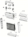
Fig. 1 is an exploded view of a lighting fixture according to a first embodiment.
Fig. 2 is an enlarged view of a portion a in fig. 1.
Fig. 3 is a partial view of the fixation plate of fig. 1.
Fig. 4 is an exploded view of the light source module of fig. 1.
Fig. 5 is a perspective view of a heat sink of a lighting fixture according to a first embodiment.
Fig. 6 is an enlarged view of a portion B in fig. 5.
Fig. 7 is an enlarged view of a portion C in fig. 5.
Fig. 8 is a partial exploded view of a lamp holder of the lighting fixture according to the second embodiment.
Detailed Description
The lamp holder and the lighting fixture of the present invention will be described in further detail with reference to the following embodiments and accompanying drawings.
Referring to fig. 1, in a first embodiment, the lighting fixture of the present invention mainly includes a lamp holder, at least one light source module 20 and a power module 30 assembled in the lamp holder. The lighting fixture shown in fig. 1 includes six light source modules. The light source modules 20 are modular and can be arranged in the lamp holder in parallel, and different sizes and powers of the lighting lamps can be formed by arranging different numbers of light source modules. Therefore, the lighting device can be made into a high-power lighting device, and needs to be matched with the high-power supply module 30.
For convenience of description, the light emitting direction side of the light source module is defined as front/front, and the side facing away from the light emitting direction is defined as back/back.
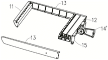
The lamp holder is made of metal/alloy materials with good heat conduction performance, and is made of aluminum materials or aluminum alloys in the embodiment, so that the lamp holder can be used as radiators of the power supply module and the light source module, and the heat dissipation efficiency of the lamp is improved. The lamp holder mainly comprises a front end fixing part 11 and a power supply cavity 12 which are arranged in a spaced and opposite mode, two fixing arms 13 which are arranged in a spaced and opposite mode, and a lamp arm 14 which is rotatably connected to the outer wall of the power supply cavity 12.
The ends of the two fixing arms 13 are respectively connected to the front end fixing portion 11 and the end of the power supply cavity 12, so that the front end fixing portion 11 and the power supply cavity 12 are bridged, and the lamp holder body is substantially in a hollow square frame shape. The front end fixing portion 11 and the power supply cavity 12 are formed with steps 111 for fixing two end portions of the light source modules 20 arranged side by side and at intervals. The light source modules 20 are arranged at intervals, and natural wind can be used for dissipating heat of the light source modules 20, so that the heat dissipation efficiency is improved.
The lamp arm 14 rotatably fixed on the power supply cavity 12 is used for connecting with a lamp post, so that the angle between the lighting lamp and the lamp arm 14 can be adjusted, and the lamp post is suitable for lamp posts with different heights. Particularly, the lamp arm 14 is led out from one side of the power supply cavity 12, and compared with the scheme that the lamp arms are led out from two ends of the power supply cavity 12, the whole streamline of the lighting lamp is better, and the appearance is more attractive.
Referring to fig. 2 and fig. 3, a card slot 124 is formed on an inner wall of the power cavity 12, and an inlet of the card slot 124 faces an opening of the power cavity (in the embodiment, the opening is located opposite to the fixing arm 13). A fixing plate 123 for fixing the power module 30 is detachably provided in the card slot 124. The fixing plate 123 includes a rectangular base 1231 and a pair of flanges 1232 extending substantially perpendicularly from both sides of the base 1231. The fixing plate 123 is detachably disposed in the power supply chamber 12 in such a manner that the folded edge 1232 is inserted into the inlet of the card slot 124.
More specifically, in the present embodiment, the power supply cavity 12 is an extruded hollow profile, and includes a front plate 121, a rear plate 122 and side plates connecting the front plate and the rear plate, which are oppositely disposed, and the power supply cavity 12 is formed with openings at both ends and sealed by the fixing arm 13. Wherein, a card slot 124 is formed on the opposite side of the front plate 121 and the back plate 122, the extending direction of the card slot 124 is the same as the extrusion direction of the section bar, and the inlet of the card slot 124 is positioned at the opening of the power supply cavity 12. The card slot 124 includes a vertical wall 1211 and an L-shaped folded wall 1212, wherein the folded wall 1212 includes a portion parallel to the vertical wall 1211 and perpendicular to the front plate 121 and a portion extending toward the vertical wall 1211. And a gap larger than or equal to the thickness of the fixing plate is formed between the end of the folding wall 1212 and the vertical wall 1211. Correspondingly, a card slot 124 formed by a vertical wall 1211 and an L-shaped folding wall 1212 is also formed on one surface of the back plate 122 facing the front plate 121. The folded edge 1232 of the fixing plate 123 is matched with the folded wall 1212, so that the folded edge of the fixing plate 123 can be inserted into the clamping groove 124 of the front plate 121 and the rear plate 122, and the folded edge 1232 is buckled with the folded wall 1212, so that the fixing plate 123 can be detachably connected with the front plate 121 and the rear plate 122. The fixing plate 123 is preferably made of metal or metal alloy with good heat conductivity, and in this embodiment, is an aluminum alloy profile, which is convenient and fast to manufacture and has a stable structure.
The power module 30 of the lighting fixture is fastened on the fixing plate 123 through a fastening member, for example, a screw 31, so that the surface of the power module 30 is tightly attached to the fixing plate 123, the heat of the power module 30 can be efficiently conducted to the fixing plate 123, and then conducted to the power cavity 12 through the fixing plate 123, so that the whole lamp holder can be used as a heat dissipation structure of the power module, and the service life of the power module is prolonged.
In addition, the power module 30 may further have heat dissipation fins 32 formed thereon, and heat of the power module 30 may also be dissipated into the power cavity 12 through the heat dissipation fins 32, so that the heat is conducted to the power cavity 12 through air heat, thereby further increasing the heat dissipation efficiency.
Referring to fig. 4 to fig. 7, the light source module 20 mainly includes a heat sink 21, a circuit board 22 having one surface closely attached to the heat sink 21, an optical cover 23, and a fixing member 24. The fixing member 24 is connected with the heat sink 21, so that the optical cover 23 is pressed on the heat sink 21 in a manner that two sides of the optical cover are uniformly stressed, and the circuit board 22 is sealed between the optical cover and the heat sink.
One surface (back surface) of the circuit board 22 is in close contact with the heat sink 21, and the other surface (front surface) is provided with a plurality of light sources 221, which are LED light sources in this embodiment. The circuit board 22 is generally (substantially or approximately, as determined by one of ordinary skill) in the form of a rectangular plate having a width and length that are less than the width and length of the surface of the heat sink 21.
The optical cover 23 is preferably made of a transparent PC material with stable chemical properties. The optical cover 23 serves as a protective cover, a sealing cover, and an optical processing device for the light sources 221, and has a plurality of optical lenses 231 formed thereon in one-to-one correspondence with the light sources 221 on the circuit board to achieve a specific light effect.
The back of the optical cover 23 is formed with an annular groove for fixing the seal ring 26. Thus, water vapor can be prevented from entering the space where the circuit board 22 is located from the gap at the joint of the optical cover 23 and the heat sink, and good waterproof performance can be achieved. A groove or step 232 recessed upward and downward is formed on the long edge of the front surface of the optical cover 23. Preferably, the groove or step 232 extends through one end of the long side and does not extend through the other end of the long side to provide a stop.
The heat sink 21 has a flat fixing surface. Specifically, in this embodiment, the heat sink 21 mainly adopts an aluminum profile with a certain bend, and includes a rectangular first heat transfer plate 211 having a flat fixing surface, two second heat transfer plates 212 integrally extending from two sides (referring to long sides of the first heat transfer plate) of the back surface of the first heat transfer plate 211 or from positions close to the two sides, and a third heat transfer plate 213 connecting ends of the two second heat transfer plates. The first heat transfer plate, the second heat transfer plate, and the third heat transfer plate are each substantially rectangular plate-shaped, and the width of the third heat transfer plate 213 is smaller than the width of the first heat transfer plate 211. Preferably, the third heat transfer plate is parallel to the first heat transfer plate. The outer surface of the second heat transfer plate 212 integrally extends to form a plurality of heat dissipation fins 2121 parallel to the first heat transfer plate 211 or perpendicular to the second heat transfer plate 212. Therefore, on the premise of keeping the inner space of the radiator (being used for wiring and fixing small electronic equipment) larger, the area of the radiating fins is enlarged as much as possible, the radiating effect of the radiator is increased, and the radiator can be adapted to light sources with various powers.
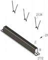
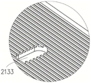
A plurality of second heat dissipation fins 2131 integrally extend from the back surface of the third heat transfer plate 213. The second heat dissipating fins 2131 are preferably perpendicular to the third heat transferring plate 213 and have a low height, so that dirt and dirt are not easily stored, large dirt is not easily caught in the grooves 2132 between the second heat dissipating fins, and accumulated dust is easily washed away by rain.
In addition, the third heat transfer plate 213 has a plurality of through holes 2133 for fixing the bird guard 2134. The bird repelling device 2134 is formed by bending a single metal wire, and includes an elastically deformable fixing portion and two extension arms extending from the fixing portion, and the fixing portion is inserted into the through hole 2133 of the third heat transfer plate 213 to be fixed.
When assembling a plurality of light source modules, all leave the space between a plurality of light source modules 20, above-mentioned space forms the convection current groove between different light source modules 20, allows the air to get into between the second heat transfer plate to can utilize the chimney effect that hot-air rises cold air and supplyes to let the air produce the convection current and directly take away the heat on second heat transfer plate and the third heat transfer plate, thereby improve the radiating effect.
In addition, the length of the second heat transfer plate 212 and the third heat transfer plate 213 is smaller than that of the first heat transfer plate 211, so that when the third heat transfer plate 213 covers part of the first heat transfer plate 211 as seen from the lower surface perpendicular to the first heat transfer plate, the two ends of the first heat transfer plate 211 are in a state of extending out of the heat radiator 21 and can be bridged on the lamp holder, and therefore heat on the heat radiator 21 can be quickly transferred to the lamp holder, and the heat dissipation effect is better. The heat sink can be considered part of the lamp holder.
The first heat transfer plate 211 is further provided with wire holes and fixing holes, so that wires led out of the circuit board 22 can penetrate through the wire holes to the back of the first heat transfer plate 211, and the circuit board 22 can be fastened on the radiator through screws, so that the back of the circuit board is in close contact with the radiator, and the heat conduction effect is ensured.
The back of the first heat transfer plate 211 is also formed with a rib 2112, the rib 2112 is parallel to the long side of the first heat transfer plate, the fixing hole formed on the first heat transfer plate preferably does not penetrate the first heat transfer plate, and the fixing hole is arranged opposite to the rib 2112. Thus, the sealing performance of the light source module can be ensured, and the strength of the radiator can be increased.
The first heat transfer plate 211 has two side walls as long sides, and slide grooves 2114 are formed through the first and second sides. Specifically, the sliding groove 2114 is recessed from a side wall of the first heat transfer plate 211 toward the other side wall opposite thereto, and penetrates the entire side wall in the direction in which the long side extends.
In this embodiment, the optical cover 23 and the heat sink 21 are fixedly connected by the fixing member 24, and the optical cover 23 is not screwed to the heat sink by a fastening member such as a screw. The fixing member 24 is used for connecting with the heat sink 21 to press the optical cover 23 on the heat sink 21 in a manner that two long sides of the optical cover are uniformly stressed. In this embodiment, the fixing member 24 includes two sliders oppositely disposed, each slider includes a strip-shaped substrate and two slide rails extending from two long sides of the substrate, and the two slide rails are oppositely disposed to form a claw shape. One of the slide rails is inserted into the slide groove 2114 on the side wall of the first heat transfer plate 211, and the other slide rail is inserted into the groove or step 232 of the optical cover 23 and pressed against the bottom of the groove or step 232 from top to bottom. Thus, the two long sides of the optical cover are pressed on the heat radiator in a uniformly stressed mode.
The utility model discloses a light source module seals circuit board 23 in the sealed space that optical cover 23 and radiator 21 enclose by setting up at optical cover 23 below groove 2342 inboard waterproof rubber ring 26, setting in the line hole of radiator 21 and the waterproof rubber seat of fixed orifices or other sealing members or sealed glue. Because the optical cover is fixed on the radiator in a way that the long edge of the optical cover is uniformly stressed, the optical cover is not easy to crack even if the optical cover becomes brittle due to being exposed to alkaline environment, and the service performance can be ensured.
In the above embodiment, each heat sink is provided with two circuit boards and two optical covers. It will be appreciated that in other embodiments, only one circuit board and one optical cover may be provided, or one optical cover may be provided to receive two or more circuit boards. Of course, the light source module can be further expanded according to requirements, and only the size of the radiator needs to be adjusted. It will be appreciated that in other variations, three or more sets of circuit boards and optical covers may also be provided on each heat sink.
It is understood that in other embodiments, the optical cover may be fixed to the heat sink by other fixing members, such as screws.
In the above embodiment, the length of the fixing member 24 is substantially the same as the length of the long side of the first heat transfer plate of the heat sink, so that the long side of the optical cover is uniformly stressed. It will be appreciated that in other embodiments, the fixing member may be divided into separate segments instead of a single fixing member. Alternatively, the optical cover and the heat sink may be attached by directly clamping the edges of the optical cover and the first heat transfer plate using a retractable clip.
It will be appreciated that the fasteners such as screws preferably use spacers or washers, and that the surfaces of the spacers or washers that contact the mounting surface preferably conform to the mounting surface, thereby increasing the strength of the connection.
Fig. 8 is a partial exploded view of a lamp holder of a lighting fixture according to a second embodiment. Compared with the first embodiment, the second embodiment is different from the first embodiment mainly in that the power supply cavity occupied by the lamp arm 14' of the lamp holder is smaller in area towards the lamp post and is of a single-arm structure.
In addition, a sighting telescope 15 for determining the irradiation direction of the lighting lamp is fixed on the lamp holder. When the lighting lamp is installed, the installation angle of the lighting lamp can be determined through the sighting telescope 15, and the installation accuracy of the lighting lamp is ensured. The scope 15 may be secured to the power supply cavity 12 adjacent the lamp arm 14' by a barrel fastener.
It is understood that in other embodiments, the sighting telescope may be fixed by forming a mounting hole in the lamp holder 10.
It can be understood that the lamp holder in the first embodiment can also be provided with a sighting telescope.
In the above embodiment, the clamping groove is formed by the vertical wall protruding from the inner wall of the power supply cavity and the L-shaped folding wall, and it can be understood that in other embodiments, the clamping groove may be a groove with an L-shaped cross section and formed by recessing from the inner wall of the power supply cavity.
While the invention has been described in conjunction with the specific embodiments set forth above, it is evident that many alternatives, modifications, and variations will be apparent to those skilled in the art in light of the foregoing description. Accordingly, it is intended to embrace all such alternatives, modifications, and variations that fall within the spirit and scope of the appended claims.
Claims (10)
1. A lamp holder comprises a power supply cavity and is characterized in that opposite clamping grooves are formed in the inner wall of the power supply cavity, the inlet of each clamping groove faces to the opening of the power supply cavity, and fixing plates for fixing a power supply module are detachably arranged in the clamping grooves; the fixing plate comprises a rectangular base plate and folded edges which extend out from two side edges of the base plate basically and vertically; the fixing plate is detachably arranged in the power supply cavity in a mode that a folded edge is inserted into the inlet of the clamping groove.
2. The lamp holder according to claim 1, wherein the engaging groove includes a vertical wall and an L-shaped folded wall extending from an inner wall of the power supply chamber, the L-shaped folded wall includes a portion substantially parallel to the vertical wall and a portion extending toward the vertical wall, and a gap greater than or equal to a thickness of the fixing plate is formed between an end of the folded wall and the vertical wall.
3. The lamp holder according to claim 1, wherein the power supply cavity is a hollow tubular section, and the vertical wall and the folded wall of the clamping groove are integrally formed with the power supply cavity body.
4. The lamp holder of claim 1, further comprising:
a front end fixing part opposite to the power supply cavity in a spaced mode;
the lamp arm is rotatably connected to the outer wall of the power supply cavity and is used for connecting a lamp post; and
two fixed arms which are oppositely arranged and are connected with the front end fixing part and the end part of the power supply cavity;
step-shaped structures are formed on the front end fixing part and the power supply cavity and used for fixing a plurality of radiators which are arranged side by side at intervals.
5. The lamp holder of claim 4, wherein the heat sink comprises: a first heat transfer plate having a smooth surface, two second heat transfer plates extending from or near both sides of a lower surface of the first heat transfer plate, and a third heat transfer plate connecting ends of the two second heat transfer plates; the first heat transfer plate, the second heat transfer plate and the third heat transfer plate are all in a substantially rectangular plate shape, and the width of the third heat transfer plate is smaller than that of the first heat transfer plate; the second heat transfer plate is extended integrally to form a plurality of heat dissipation fins parallel to the first heat transfer plate, and the third heat transfer plate is extended integrally to form a plurality of heat dissipation fins parallel to the long side of the third heat transfer plate.
6. The lamp holder according to claim 5, wherein a rib is formed on a back surface of the first heat transfer plate, a plurality of fixing holes which do not penetrate through the first heat transfer plate are formed on the first heat transfer plate, and the fixing holes are arranged opposite to the rib.
7. The lamp holder of claim 5 wherein said third heat transfer plate has a plurality of through holes formed therein for securing an anti-bird device thereto.
8. The lamp holder of claim 7 wherein said bird guard is a single wire folded structure including a resiliently deformable mounting portion and two extension arms extending from said mounting portion, said mounting portion adapted to be inserted into said through holes in said third heat transfer plate.
9. The lamp holder according to claim 4, wherein a sighting telescope for determining the irradiation direction of the lighting fixture is further fixed on the outer wall of the power supply cavity.
10. An illumination lamp comprising a lamp holder and a plurality of light source modules fixed in the lamp holder, wherein the lamp holder is the lamp holder according to any one of claims 1 to 9.
Priority Applications (1)
| Application Number | Priority Date | Filing Date | Title |
|---|---|---|---|
| CN202221513996.2U CN217540672U (en) | 2022-06-16 | 2022-06-16 | Lamp bracket and lighting lamp |
Applications Claiming Priority (1)
| Application Number | Priority Date | Filing Date | Title |
|---|---|---|---|
| CN202221513996.2U CN217540672U (en) | 2022-06-16 | 2022-06-16 | Lamp bracket and lighting lamp |
Publications (1)
| Publication Number | Publication Date |
|---|---|
| CN217540672U true CN217540672U (en) | 2022-10-04 |
Family
ID=83420412
Family Applications (1)
| Application Number | Title | Priority Date | Filing Date |
|---|---|---|---|
| CN202221513996.2U Active CN217540672U (en) | 2022-06-16 | 2022-06-16 | Lamp bracket and lighting lamp |
Country Status (1)
| Country | Link |
|---|---|
| CN (1) | CN217540672U (en) |
-
2022
- 2022-06-16 CN CN202221513996.2U patent/CN217540672U/en active Active
Similar Documents
| Publication | Publication Date | Title |
|---|---|---|
| US10393360B2 (en) | LED luminaire having lateral cooling fins and adaptive LED assembly | |
| US9982879B2 (en) | LED lighting apparatus having a plurality of light emitting module sections interlocked in a circular fashion | |
| KR100974942B1 (en) | LED Streetlight | |
| KR101421407B1 (en) | LED floodlight | |
| WO2019010852A1 (en) | Illumination lamp | |
| TW201248061A (en) | Connecting member and LED lamp using the same | |
| KR101408824B1 (en) | Led floodlight and manufacturing method thereof | |
| US10041641B2 (en) | LED streetlamp | |
| CN217540672U (en) | Lamp bracket and lighting lamp | |
| CN208504104U (en) | A kind of LED lamp profile external member | |
| KR20120059041A (en) | a frame for light-instrument with radiation of heat and LED lighting using frame | |
| CN209944268U (en) | High heat dissipation type LED lamp with flat plate structure | |
| CN217540514U (en) | Light source module and lighting lamp | |
| CN216591584U (en) | Lamp set | |
| CN218864126U (en) | Outdoor waterproof projecting lamp | |
| TWM592938U (en) | Lamp device and lamp carrier board | |
| CN215892266U (en) | Lamp and base for lamp | |
| CN113834012A (en) | Projection lamp | |
| CN213272161U (en) | Street lamp holder | |
| CN220152686U (en) | LED lamp source heat dissipation module and lamp with same | |
| RU141148U1 (en) | ELECTRIC LIGHT | |
| CN214369783U (en) | Low-power consumption anti-interference small night lamp | |
| CN221098558U (en) | Mounting substrate of bar lamp | |
| CN219530621U (en) | Wall lamp with detachable light source module | |
| CN214745101U (en) | Projecting lamp accessory |
Legal Events
| Date | Code | Title | Description |
|---|---|---|---|
| GR01 | Patent grant | ||
| GR01 | Patent grant |