CN217535066U - Line winding displacement ware that fitment was used - Google Patents
Line winding displacement ware that fitment was used Download PDFInfo
- Publication number
- CN217535066U CN217535066U CN202221674109.XU CN202221674109U CN217535066U CN 217535066 U CN217535066 U CN 217535066U CN 202221674109 U CN202221674109 U CN 202221674109U CN 217535066 U CN217535066 U CN 217535066U
- Authority
- CN
- China
- Prior art keywords
- wall
- disc
- frame body
- framework
- threaded rod
- Prior art date
- Legal status (The legal status is an assumption and is not a legal conclusion. Google has not performed a legal analysis and makes no representation as to the accuracy of the status listed.)
- Active
Links
Images


Landscapes
- Earth Drilling (AREA)
Abstract
The utility model belongs to the technical field of the winding displacement equipment, and a circuit winding displacement ware that fitment was used is disclosed, the fruit pick-up device comprises a frame body, the spout has been seted up to the inside equidistance of framework, the slider has been cup jointed in the inside activity of spout, and the internal thread of slider has cup jointed the threaded rod, and the lower extreme of threaded rod runs through the framework and cup joints with the inner wall activity of framework, and the upper end of threaded rod runs through the framework and fixedly connected with is located the outside rotary rod of framework and cup joints with the inner wall activity of framework. The utility model discloses a set up threaded rod and rotary rod, disc, through rotating the rotary rod to will drive the stopper and take place to rotate and carry on spacingly to the threaded rod along the inner wall of framework, will drive the slider simultaneously and take place the rebound along the inner wall of spout, and then will drive the whole rebound of disc, and tighten up the electric wire of disc surface winding, thereby make the electric wire can not drop because too loose from winding displacement ware inside, and then reach the purpose of tightening up the electric wire.
Description
Technical Field
The utility model belongs to the technical field of the winding displacement equipment, specifically a circuit winding displacement ware that fitment was used.
Background
At present, operating personnel carries out the in-process of fitment at the house, often need be in house internally mounted circuit in order to ensure the house circular telegram, and operating personnel is at the in-process of installation circuit simultaneously, in order to guarantee the neat use of circuit, often need use the winding displacement ware to separately arrange the electric wire.
At present, in the process of actual use of the wire arranging device in the prior art, although the purpose of basically arranging the wires separately can be achieved, due to the lack of a structure for well tightening the wires, when the wires are too long due to installation errors of operators, the wires are likely to be too loose due to too long, and at the moment, the wires are easy to fall off from the inside of the wire arranging device, and normal use of the wires is affected, so that the wire arranging device needs to be improved.
SUMMERY OF THE UTILITY MODEL
The utility model aims at above problem, the utility model provides a circuit winding displacement ware that fitment was used has the advantage of tightening up the electric wire.
In order to achieve the above object, the utility model provides a following technical scheme: the utility model provides a circuit winding displacement ware that fitment was used, includes the framework, the spout has been seted up to the inside equidistance of framework, the slider has been cup jointed in the inside activity of spout, the threaded rod has been cup jointed to the inside screw thread of slider, the lower extreme of threaded rod runs through the framework and cup joints with the inner wall activity of framework, the upper end of threaded rod runs through the framework and fixedly connected with is located the outside rotary rod of framework and cup joints with the inner wall activity of framework, the outer fixed surface of threaded rod has cup jointed the stopper that is located the framework inside, the surface of stopper cup joints with the inner wall activity of framework, the right side fixed mounting of slider has the disc that is located the spout outside, the left end of disc surface is fixed and has been cup jointed the ring, the side of ring and disc all with the inner wall swing joint of framework, the notch has been seted up to the inside of disc right-hand member, the inside activity of notch has cup jointed the dog, the top of dog is located the top of disc, the inside upper and lower both ends of disc have all seted up and are located left draw-in groove.
As the utility model discloses preferred, the equal fixed mounting in both sides about the dog has the side piece, the surface of side piece cup joints with the inner wall activity of notch.
As the utility model discloses it is preferred, the cavity has been seted up to the inside of dog bottom, the movable block has been cup jointed in the inside activity of cavity.
As the utility model discloses preferred, the fixed joint in inside of movable block has the kelly, the left end of kelly runs through the dog and extends to the inside of draw-in groove.
As the utility model discloses preferred, the right-hand member of kelly runs through the dog and extends to the outside of dog, the surface of kelly cup joints with the inner wall activity of dog.
As the utility model discloses it is preferred, the surface activity of kelly has cup jointed the stiff spring that is located between movable block right side and the cavity inner wall, the one end of stiff spring and the right side fixed connection of movable block, the other end of stiff spring and the inner wall fixed connection of cavity.
As the utility model discloses preferred, the equal fixed mounting in both sides about the framework has the installation piece, the mounting hole has been seted up to the inside of installation piece.
Compared with the prior art, the beneficial effects of the utility model are as follows:
1. the utility model discloses a set up threaded rod and rotary rod, disc, through rotating the rotary rod to will drive the stopper and take place to rotate and carry on spacingly to the threaded rod along the inner wall of framework, will drive the slider simultaneously and take place the rebound along the inner wall of spout, and then will drive the whole rebound of disc, and tighten up the electric wire of disc surface winding, thereby make the electric wire can not drop because too loose from the winding displacement ware inside, and then reach the purpose of tightening up the electric wire.
2. The utility model discloses a set up the kelly, draw-in groove and stiff spring, through pulling the kelly, thereby will drive the movable block and take place to remove and compress the stiff spring along the inner wall of cavity, will make the kelly break away from the inside of draw-in groove this moment, and remove the holistic fixed effect to the dog, then through the downwards pulling kelly, thereby will drive inside dog and side piece take place to move income notch downwards along the inner wall of notch, then through loosening the kelly, thereby will make the stiff spring extrusion movable block drive the kelly and remove to the inside dog whole of fixing of draw-in groove that corresponds, alright take out the winding electric wire from the surface of disc afterwards and examine, thereby reached the purpose of convenient to detach electric wire maintenance.
Drawings
FIG. 1 is a schematic structural view of the present invention;
fig. 2 is a schematic side sectional structural view of the rotary rod of the present invention;
fig. 3 is a schematic structural view of the threaded rod of the present invention;
FIG. 4 is a schematic view of the disc structure of the present invention;
FIG. 5 is a schematic side view of the disc of the present invention;
FIG. 6 is an enlarged view of a portion A of FIG. 2;
fig. 7 is a schematic view of a part of the enlarged structure at B in fig. 2.
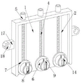
In the figure: 1. a frame body; 2. a chute; 3. a slider; 4. a threaded rod; 5. rotating the rod; 6. a disc; 7. a circular ring; 8. a notch; 9. a stopper; 10. a limiting block; 11. a side block; 12. a cavity; 13. a moving block; 14. a clamping rod; 15. a card slot; 16. a rigid spring; 17. mounting a block; 18. and (7) installing holes.
Detailed Description
The technical solutions in the embodiments of the present invention will be described clearly and completely with reference to the accompanying drawings in the embodiments of the present invention, and it is obvious that the described embodiments are only some embodiments of the present invention, not all embodiments. Based on the embodiments in the present invention, all other embodiments obtained by a person skilled in the art without creative efforts all belong to the protection scope of the present invention.
As shown in fig. 1 to 7, the utility model provides a circuit winding displacement ware that fitment was used, including framework 1, spout 2 has been seted up to framework 1's inside equidistance, slider 3 has been cup jointed in the inside activity of spout 2, threaded rod 4 has been cup jointed to slider 3's internal thread, threaded rod 4's lower extreme runs through framework 1 and cup joints with framework 1's inner wall activity, threaded rod 4's upper end runs through framework 1 and fixedly connected with is located framework 1 outside rotary rod 5 and cup joints with framework 1's inner wall activity, threaded rod 4's surface fixation has cup jointed stopper 10 that is located framework 1 inside, stopper 10's surface and framework 1's inner wall activity cup joint, slider 3's right side fixed mounting has the disc 6 that is located spout 2 outside, the left end of disc 6 surface is fixed and has been cup jointed ring 7, the side of ring 7 and disc 6 all with framework 1's inner wall swing joint, notch 8 has been seted up to the inside of disc 6 right-hand member, dog 9 has been cup jointed in the inside activity of notch 8, the top of dog 9 is located the top of 6, the upper and lower both ends of disc 6 inside have all seted up and are located left dog 9 draw-in the draw-in groove 15.
Referring to fig. 4, side blocks 11 are fixedly mounted on the left and right sides of the stopper 9, and the outer surfaces of the side blocks 11 are movably sleeved with the inner wall of the notch 8.
As a technical optimization scheme of the utility model, because the design of side piece 11 to will make it carry on spacingly to dog 9, and then make dog 9 can only take place to reciprocate.
Referring to fig. 5, a cavity 12 is formed in the bottom end of the stopper 9, and a moving block 13 is movably sleeved in the cavity 12.
As a technical optimization scheme of the utility model, the surface of movable block 13 and the inner wall of cavity 12 are all smooth, consequently will make movable block 13 more smooth at the in-process of motion.
Referring to fig. 5, a clamping rod 14 is fixedly sleeved inside the moving block 13, and the left end of the clamping rod 14 penetrates through the stop 9 and extends into the clamping groove 15.
As a technical optimization scheme of the utility model, because mutually supporting between kelly 14 and the draw-in groove 15 to will make kelly 14 play good fixed effect to dog 9 is whole through draw-in groove 15.
Referring to fig. 5, the right end of the rod 14 extends through the stopper 9 and extends to the outside of the stopper 9, and the outer surface of the rod 14 is movably sleeved on the inner wall of the stopper 9.
As a technical optimization scheme of the utility model, when operating personnel pulling kelly 14 to will make kelly 14 break away from the inside of draw-in groove 15, and then has removed the holistic fixed effect to dog 9.
Referring to fig. 5, a rigid spring 16 located between the right side of the moving block 13 and the inner wall of the cavity 12 is movably sleeved on the outer surface of the clamping rod 14, one end of the rigid spring 16 is fixedly connected with the right side of the moving block 13, and the other end of the rigid spring 16 is fixedly connected with the inner wall of the cavity 12.
As a technical optimization scheme of the utility model, because the design of stiff spring 16 to will make the movable block 13 have good elasticity reset function, and then make the movable block 13 drive kelly 14 take place to remove inseparabler with draw-in groove 15's inner wall laminating.
Referring to fig. 1, mounting blocks 17 are fixedly mounted on both left and right sides of the frame 1, and mounting holes 18 are formed in the mounting blocks 17.
As a technical optimization scheme of the utility model, because the design of mounting hole 18 to will make operating personnel can use installation piece 17 and framework 1 monolithic stationary on the wall body through mounting hole 18 with the screw.
The utility model discloses a theory of operation and use flow:
at first, operating personnel uses the screw through mounting hole 18 with installation piece 17 and framework 1 monolithic fixation on the wall body, then operating personnel twines the electric wire respectively on the surface of disc 6, this moment because mutually support between ring 7 and dog 9, thereby will make the electric wire can not break away from the surface of disc 6, when the electric wire is too loose afterwards, operating personnel is through rotating rotary rod 5 this moment, thereby will drive slider 3 and take place to move upwards along the inner wall of spout 2, and then will drive the whole rebound of disc 6, and tighten up the electric wire of disc 6 surface winding, and then reach the purpose of tightening up the electric wire.
When needs inspect the electric wire, operating personnel can pass through pulling kelly 14 this moment, thereby will drive movable block 13 and take place to remove and compress rigid spring 16 along the inner wall of cavity 12, and then will drive kelly 14 and break away from the inside of draw-in groove 15, then operating personnel stimulates kelly 14 downwards, thereby will drive dog 9 and side piece 11 and take place to move downwards along the inner wall of notch 8 and remove spacing to the electric wire, operating personnel is through loosening kelly 14 this moment, thereby will make rigid spring 16 extrude movable block 13 and drive kelly 14 and remove to inside fixing dog 9 wholly of draw-in groove 15 that corresponds, operating personnel alright follow the surface of winding electric wire from disc 6 and take out and inspect afterwards, thereby make operating personnel not hard rotation rotary rod 5 remove the fixed to the electric wire, and then reached the purpose of being convenient for dismantling the electric wire maintenance.
It is noted that, herein, relational terms such as first and second, and the like may be used solely to distinguish one entity or action from another entity or action without necessarily requiring or implying any actual such relationship or order between such entities or actions. Also, the terms "comprises," "comprising," or any other variation thereof, are intended to cover a non-exclusive inclusion, such that a process, method, article, or apparatus that comprises a list of elements does not include only those elements but may include other elements not expressly listed or inherent to such process, method, article, or apparatus.
Although embodiments of the present invention have been shown and described, it will be appreciated by those skilled in the art that changes, modifications, substitutions and alterations can be made in these embodiments without departing from the principles and spirit of the invention, the scope of which is defined in the appended claims and their equivalents.
Claims (7)
1. The utility model provides a circuit winding displacement ware that fitment was used, includes framework (1), its characterized in that: sliding chutes (2) are equidistantly arranged in the frame body (1), sliding blocks (3) are movably sleeved in the sliding chutes (2), a threaded rod (4) is sleeved on the inner thread of the sliding block (3), the lower end of the threaded rod (4) penetrates through the frame body (1) and is movably sleeved with the inner wall of the frame body (1), the upper end of the threaded rod (4) penetrates through the frame body (1), is fixedly connected with a rotating rod (5) positioned outside the frame body (1) and is movably sleeved with the inner wall of the frame body (1), the outer surface of the threaded rod (4) is fixedly sleeved with a limiting block (10) positioned in the frame body (1), the outer surface of the limiting block (10) is movably sleeved with the inner wall of the frame body (1), a disc (6) positioned outside the sliding chute (2) is fixedly arranged on the right side of the sliding block (3), a circular ring (7) is fixedly sleeved at the left end of the outer surface of the disc (6), the side surfaces of the circular ring (7) and the disc (6) are movably connected with the inner wall of the frame body (1), a notch (8) is arranged inside the right end of the disc (6), a stop block (9) is movably sleeved in the notch (8), the top end of the stop block (9) is positioned above the disc (6), the upper end and the lower end of the inner part of the disc (6) are provided with clamping grooves (15) positioned on the left side of the stop block (9).
2. A finishing line organizer as claimed in claim 1, in which: the equal fixed mounting in both sides about dog (9) has side piece (11), the surface of side piece (11) cup joints with the inner wall activity of notch (8).
3. A finishing line organizer as claimed in claim 1, in which: a cavity (12) is formed in the bottom end of the stop block (9), and a moving block (13) is movably sleeved in the cavity (12).
4. A finishing line organizer as claimed in claim 3, in which: a clamping rod (14) is fixedly sleeved in the moving block (13), and the left end of the clamping rod (14) penetrates through the stop block (9) and extends into the clamping groove (15).
5. A finishing line striper as claimed in claim 4, wherein: the right end of the clamping rod (14) penetrates through the stop block (9) and extends to the outside of the stop block (9), and the outer surface of the clamping rod (14) is movably sleeved with the inner wall of the stop block (9).
6. A finishing line striper as claimed in claim 4, wherein: the outer surface of the clamping rod (14) is movably sleeved with a rigid spring (16) located between the right side of the moving block (13) and the inner wall of the cavity (12), one end of the rigid spring (16) is fixedly connected with the right side of the moving block (13), and the other end of the rigid spring (16) is fixedly connected with the inner wall of the cavity (12).
7. A finishing line organizer as claimed in claim 1, in which: the frame is characterized in that mounting blocks (17) are fixedly mounted on the left side and the right side of the frame body (1), and mounting holes (18) are formed in the mounting blocks (17).
Priority Applications (1)
| Application Number | Priority Date | Filing Date | Title |
|---|---|---|---|
| CN202221674109.XU CN217535066U (en) | 2022-07-01 | 2022-07-01 | Line winding displacement ware that fitment was used |
Applications Claiming Priority (1)
| Application Number | Priority Date | Filing Date | Title |
|---|---|---|---|
| CN202221674109.XU CN217535066U (en) | 2022-07-01 | 2022-07-01 | Line winding displacement ware that fitment was used |
Publications (1)
| Publication Number | Publication Date |
|---|---|
| CN217535066U true CN217535066U (en) | 2022-10-04 |
Family
ID=83421545
Family Applications (1)
| Application Number | Title | Priority Date | Filing Date |
|---|---|---|---|
| CN202221674109.XU Active CN217535066U (en) | 2022-07-01 | 2022-07-01 | Line winding displacement ware that fitment was used |
Country Status (1)
| Country | Link |
|---|---|
| CN (1) | CN217535066U (en) |
-
2022
- 2022-07-01 CN CN202221674109.XU patent/CN217535066U/en active Active
Similar Documents
| Publication | Publication Date | Title |
|---|---|---|
| CN213452614U (en) | Intelligent safety monitoring device for communication machine room | |
| CN110798595A (en) | Real-time online remote video intelligent monitoring technology | |
| CN113701874A (en) | Noise detection device with mounting structure and detection method thereof | |
| CN217535066U (en) | Line winding displacement ware that fitment was used | |
| CN205164347U (en) | Filter screen dust collector | |
| CN217955610U (en) | Filter capacitor reactor convenient to installation | |
| CN204387620U (en) | A kind of liftable support for monitoring camera machine head | |
| CN208634713U (en) | A kind of removable monitoring device in building site | |
| CN115939945A (en) | Power grid line detection system | |
| CN216122724U (en) | Router switch is hung and is put with bearing device | |
| CN210297867U (en) | Monitoring equipment for public management | |
| CN112283561A (en) | Intelligent monitoring anti-theft system for office | |
| CN207354490U (en) | A kind of multifunctional monitoring device | |
| CN214119598U (en) | Safety monitoring device based on artificial intelligence | |
| CN112285408A (en) | Voltage stability monitoring device and method for large outdoor transformer | |
| CN212785611U (en) | Multimedia intelligent building security monitoring system | |
| CN111786880A (en) | Gateway device of Internet of things | |
| CN208505855U (en) | A kind of fugitive dust index detection device with dust reduction capability | |
| CN216564072U (en) | Channel structure for in-and-out of cable in ring main unit | |
| CN206365717U (en) | Extrusion component and have its stock machine | |
| CN218510562U (en) | Monitoring equipment with AI picture recognition function | |
| CN219798531U (en) | Alarm device for noise monitoring | |
| CN108332802A (en) | A kind of internet of things data acquisition device | |
| CN214044456U (en) | Inside self-cleaning switch board | |
| CN204156334U (en) | Automation distribution control of intelligent terminal |
Legal Events
| Date | Code | Title | Description |
|---|---|---|---|
| GR01 | Patent grant | ||
| GR01 | Patent grant |