CN217531531U - Mould for manufacturing glass fiber reinforced plastics - Google Patents
Mould for manufacturing glass fiber reinforced plastics Download PDFInfo
- Publication number
- CN217531531U CN217531531U CN202122651956.6U CN202122651956U CN217531531U CN 217531531 U CN217531531 U CN 217531531U CN 202122651956 U CN202122651956 U CN 202122651956U CN 217531531 U CN217531531 U CN 217531531U
- Authority
- CN
- China
- Prior art keywords
- fixedly connected
- rod
- notch
- mould
- mold
- Prior art date
- Legal status (The legal status is an assumption and is not a legal conclusion. Google has not performed a legal analysis and makes no representation as to the accuracy of the status listed.)
- Active
Links
Images


Landscapes
- Moulds For Moulding Plastics Or The Like (AREA)
Abstract
The utility model discloses a mould for glass steel manufacturing relates to mould technical field. The utility model comprises a mould body; many spinal branchs vaulting poles of below fixedly connected with of mould body, the channel has been seted up at the middle part of bracing piece, and one side of channel is seted up flutedly, and the notch has been seted up to the top of channel, and two spouts have been seted up to the middle part fixedly connected with motor of recess, one side of notch, and the inside sliding fit of spout has the body of rod. The utility model discloses a be provided with the motor in the inside of recess, when needs remove the mould, open the motor and can make wheel contact ground, comparatively labour saving and time saving to reduced the cost of labor, be provided with the body of rod in the inside of spout, when the gag lever post is fixed to needs, promote the body of rod, make the inside of body of rod card income gag lever post, accomplish the fixed to the gag lever post, thereby promoted the stability of mould when removing.
Description
Technical Field
The utility model belongs to the technical field of the mould, especially, relate to a mould for glass steel manufacturing.
Background
The mould is various moulds and tools for obtaining required products by injection molding, blow molding, extrusion, die casting or forging forming, smelting, stamping and other methods in industrial production. In short, a mold is a tool used to make a shaped article, the tool being made up of various parts, with different molds being made up of different parts. The method realizes the processing of the shape of an article mainly through the change of the physical state of a formed material. The element has the name of "industrial mother". The blank is formed into a tool with a specific shape and size under the action of external force. The method is widely applied to blanking, die forging, cold heading, extrusion, powder metallurgy part pressing, pressure casting and the forming processing of compression molding or injection molding of products such as engineering plastics, rubber, ceramics and the like. The die has a specific contour or cavity shape, and the blank can be separated (blanked) according to the contour shape by applying the contour shape with the cutting edge. The blank can obtain a corresponding three-dimensional shape by using the shape of the inner cavity. The mold generally comprises a movable mold and a fixed mold (or a male mold and a female mold), which can be separated or combined. When the blank is closed, the blank is injected into the die cavity for forming. The die is a precise tool, has a complex shape, bears the expansion force of a blank, has higher requirements on structural strength, rigidity, surface hardness, surface roughness and processing precision, and the development level of die production is one of important marks of the mechanical manufacturing level. Besides the die itself, the die also needs a die holder, a die frame, a die core, a workpiece ejection device and the like, and the parts are generally made into universal types. The mold enterprises need to do great elaboration, product positioning and market positioning are determined according to market demands and conditions such as technology, capital and equipment, and the methods are particularly worthy of study and reference of small mold enterprises, and the technical advantages and the product advantages of the small mold enterprises are gradually formed by concentrating strength. Therefore, the mold enterprises in China must make active efforts to use the experience of the advanced enterprises abroad for better development in the future. The injection molding is that plastic is first added into a heating material cylinder of an injection machine, the plastic is heated and melted, and the plastic enters a mold cavity through a nozzle and a mold pouring system under the pushing of a screw rod or a plunger of the injection machine, and is hardened and molded into an injection molding product due to physical and chemical actions. Injection molding has a cyclic cycle consisting of injection, pressure holding (cooling) and plastic part demolding, so that injection molding has the characteristic of periodicity. The hot runner mold has the same structure as the thin nozzle, and the most difference is that the runner is in one or more hot runner plates and hot sprue nozzles with constant temperature, so that the cold material demolding is avoided, and the runner and the sprue are directly arranged on the product, so that the demolding of the runner is not needed.
Most of the existing moulds for manufacturing glass fiber reinforced plastics are inconvenient when the positions need to be changed, a large amount of manpower may need to be consumed, and the stability is not high.
SUMMERY OF THE UTILITY MODEL
An object of the utility model is to provide a mould is used in glass steel manufacturing has solved the problem that exists among the above-mentioned prior art through motor, the body of rod.
In order to achieve the purpose, the utility model is realized by the following technical proposal:
a mould for manufacturing glass fiber reinforced plastics comprises a mould body;
a plurality of support rods are fixedly connected below the die body, a channel is formed in the middle of each support rod, a groove is formed in one side of each channel, a notch is formed in the upper portion of each channel, a motor is fixedly connected to the middle of each groove, two sliding grooves are formed in one side of each notch, and a rod body is in sliding fit with the inner portion of each sliding groove;
the constant head tank has been seted up at the middle part of clamp plate to the output fixedly connected with clamp plate of motor, one side fixedly connected with dwang of constant head tank inner wall, and the middle part sliding connection of channel has the wheel, the top fixedly connected with locating lever of wheel, two plate bodys of week fixedly connected with of locating lever, the middle part elastic fit of notch has the gag lever post, and gag lever post and locating lever fixed connection.
Optionally, one side fixedly connected with spring of notch, the one end and the gag lever post fixed connection of spring, and gag lever post sliding fit is in the inside of notch.
Optionally, a clamping groove matched with the rod body is formed in one side of the limiting rod.
Optionally, the groove, the channel, the notch and the chute are communicated in sequence.
Optionally, the rotating rod is located between the two plate bodies.
Optionally, the side of the rod body is fixedly connected with a baffle matched with the notch of the sliding groove.
The embodiment of the utility model has the following beneficial effect:
the utility model discloses an embodiment is provided with the motor through the inside at the recess, when needs remove the mould, opens the motor and can make wheel contact ground, comparatively labour saving and time saving to reduced the cost of labor, be provided with the body of rod in the inside of spout, when the gag lever post is fixed to needs, promote the body of rod, make the inside of body of rod card income gag lever post, accomplish the fixed to the gag lever post, thereby promoted the stability of mould when removing.
Of course, it is not necessary for any particular product to achieve all of the above-described advantages at the same time.
Drawings
The accompanying drawings, which form a part of the present application, are included to provide a further understanding of the invention, and are incorporated in and constitute a part of this specification, illustrate embodiments of the invention and together with the description serve to explain the invention and not to limit the invention. In the drawings:
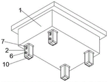
fig. 1 is a schematic view of a three-dimensional structure of a mold body according to an embodiment of the present invention;
fig. 2 is a schematic view of a three-dimensional structure of a support rod according to an embodiment of the present invention;
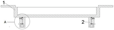
fig. 3 is a schematic cross-sectional view of a mold body according to an embodiment of the present invention;
FIG. 4 is a schematic view of the structure at A in FIG. 2;
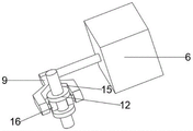
fig. 5 is a schematic view of a three-dimensional structure of a pressing plate according to an embodiment of the present invention.
Wherein the figures include the following reference numerals:
the die comprises a die body 1, a support rod 2, a channel 3, a groove 4, a notch 5, a motor 6, a sliding chute 7, a pressing plate 9, wheels 10, a positioning rod 11, a plate body 12, a limiting rod 13, a spring 14, a positioning groove 15 and a rotating rod 16.
Detailed Description
The technical solutions in the embodiments of the present invention will be described clearly and completely with reference to the accompanying drawings in the embodiments of the present invention, and it is obvious that the described embodiments are only some embodiments of the present invention, not all embodiments. The following description of at least one exemplary embodiment is merely illustrative in nature and is in no way intended to limit the invention, its application, or uses.
To maintain the following description of the embodiments of the present invention clear and concise, detailed descriptions of well-known functions and components may be omitted.
Referring to fig. 1-5, in the present embodiment, a mold for manufacturing glass fiber reinforced plastic is provided, which includes a mold body 1;
a plurality of support rods 2 are fixedly connected below the die body 1, a channel 3 is formed in the middle of each support rod 2, a groove 4 is formed in one side of each channel 3, a notch 5 is formed in the upper portion of each channel 3, a motor 6 is fixedly connected to the middle of each groove 4, two sliding grooves 7 are formed in one side of each notch 5, and a rod body is arranged in each sliding groove 7 in a sliding fit mode;
output fixedly connected with clamp plate 9 of motor 6, constant head tank 15 has been seted up at the middle part of clamp plate 9, one side fixedly connected with dwang 16 of constant head tank 15 inner wall, the middle part sliding connection of channel 3 has wheel 10, the top fixedly connected with locating lever 11 of wheel 10, two plate bodies 12 of week side fixedly connected with of locating lever 11, the middle part elastic fit of notch 5 has gag lever post 13, and gag lever post 13 and locating lever 11 fixed connection.
The application of one aspect of the embodiment is as follows: when the mould is removed to needs, stimulate the body of rod earlier, make the body of rod and spacing rod 13 cancel spacing relation, then open motor 6, make the clamp plate 9 with motor 6 output end fixed connection rotate, then clamp plate 9 drives plate body 12 up-and-down motion through dwang 16, then plate body 12 drives locating lever 11 motion, then locating lever 11 drives wheel contact ground, then promote the body of rod, make the body of rod and spacing rod 13 produce spacing relation again, thereby accomplish the removal to the mould, with the reason when needing the wheel shrink. It should be noted that the motor 6 referred to in this application may be powered by a battery or an external power source.
Be provided with motor 6 through the inside at recess 4, when needs remove the mould, open motor 6 and can make wheel contact ground, comparatively labour saving and time saving to reduced the cost of labor, be provided with the body of rod in the inside of spout 7, when needs fixed gag lever post 13, promote the body of rod, make the inside of body of rod card income gag lever post 13, the completion is fixed to gag lever post 13, thereby has promoted the stability of mould when removing.
One side fixedly connected with spring 14 of notch 5 of this embodiment, the one end and the gag lever post 13 fixed connection of spring 14, and gag lever post 13 sliding fit is in the inside of notch 5.
In this embodiment, a slot adapted to the rod body is formed in one side of the limiting rod 13.
The groove 4, the channel 3, the notch 5 and the sliding groove 7 of the embodiment are communicated in sequence.
The turning rod 16 of the present embodiment is located between the two plate bodies 12.
The baffle of the week side fixedly connected with of the body of rod of this embodiment and 7 notch departments adaptations of spout.
The above embodiments may be combined with each other.
It should be noted that the terms "first," "second," and the like in the description and claims of this application and in the drawings described above are used for distinguishing between similar elements and not necessarily for describing a particular sequential or chronological order. It is to be understood that the data so used is interchangeable under appropriate circumstances such that the embodiments of the application described herein are capable of operation in sequences other than those illustrated or described herein.
In the description of the present invention, it should be understood that the orientation or positional relationship indicated by the orientation words such as "front, back, up, down, left, right", "horizontal, vertical, horizontal" and "top, bottom" etc. are usually based on the orientation or positional relationship shown in the drawings, and are only for convenience of description and simplification of description, and in the case of not making a contrary explanation, these orientation words do not indicate and imply that the device or element referred to must have a specific orientation or be constructed and operated in a specific orientation, and therefore, should not be interpreted as limiting the scope of the present invention; the terms "inner and outer" refer to the inner and outer relative to the profile of the respective component itself.
Claims (6)
1. A mold for manufacturing glass fiber reinforced plastics is characterized by comprising: a mold body (1);
the die comprises a die body (1), wherein a plurality of supporting rods (2) are fixedly connected below the die body (1), a channel (3) is formed in the middle of each supporting rod (2), a groove (4) is formed in one side of each channel (3), a notch (5) is formed in the upper side of each channel (3), a motor (6) is fixedly connected to the middle of each groove (4), two sliding grooves (7) are formed in one side of each notch (5), and a rod body is arranged in each sliding groove (7) in a sliding fit mode;
the output end of the motor (6) is fixedly connected with a pressing plate (9), a positioning groove (15) is formed in the middle of the pressing plate (9), one side of the inner wall of the positioning groove (15) is fixedly connected with a rotating rod (16), the middle of the channel (3) is connected with wheels (10) in a sliding mode, positioning rods (11) are fixedly connected to the upper portions of the wheels (10), two plate bodies (12) are fixedly connected to the peripheral sides of the positioning rods (11), the middle of each notch (5) is in elastic fit with a limiting rod (13), and the limiting rods (13) are fixedly connected with the positioning rods (11).
2. The mold for manufacturing glass fiber reinforced plastic according to claim 1, wherein a spring (14) is fixedly connected to one side of the notch (5), one end of the spring (14) is fixedly connected to the limiting rod (13), and the limiting rod (13) is slidably fitted inside the notch (5).
3. The mold for manufacturing glass fiber reinforced plastic according to claim 1, wherein a slot adapted to the rod body is formed at one side of the limiting rod (13).
4. The mold for manufacturing glass fiber reinforced plastic according to claim 1, wherein the groove (4), the channel (3), the notch (5) and the chute (7) are communicated in sequence.
5. A mold for manufacturing glass fiber reinforced plastic according to claim 1, wherein the rotating rod (16) is located between the two plate bodies (12).
6. The mold for manufacturing glass fiber reinforced plastic according to claim 1, wherein a baffle plate adapted to the notch of the chute (7) is fixedly connected to the circumferential side of the rod body.
Priority Applications (1)
| Application Number | Priority Date | Filing Date | Title |
|---|---|---|---|
| CN202122651956.6U CN217531531U (en) | 2021-11-02 | 2021-11-02 | Mould for manufacturing glass fiber reinforced plastics |
Applications Claiming Priority (1)
| Application Number | Priority Date | Filing Date | Title |
|---|---|---|---|
| CN202122651956.6U CN217531531U (en) | 2021-11-02 | 2021-11-02 | Mould for manufacturing glass fiber reinforced plastics |
Publications (1)
| Publication Number | Publication Date |
|---|---|
| CN217531531U true CN217531531U (en) | 2022-10-04 |
Family
ID=83416720
Family Applications (1)
| Application Number | Title | Priority Date | Filing Date |
|---|---|---|---|
| CN202122651956.6U Active CN217531531U (en) | 2021-11-02 | 2021-11-02 | Mould for manufacturing glass fiber reinforced plastics |
Country Status (1)
| Country | Link |
|---|---|
| CN (1) | CN217531531U (en) |
-
2021
- 2021-11-02 CN CN202122651956.6U patent/CN217531531U/en active Active
Similar Documents
| Publication | Publication Date | Title |
|---|---|---|
| CN217531531U (en) | Mould for manufacturing glass fiber reinforced plastics | |
| CN215092661U (en) | A quick grinding machanism for processing of mould surface finish | |
| CN214108527U (en) | Environment-friendly cutlery box forming die | |
| CN212072829U (en) | Mold ejection device | |
| CN213472011U (en) | Injection mold suitable for automobile terminal | |
| CN213162711U (en) | Die-casting forming die capable of achieving rapid demoulding | |
| CN213500289U (en) | A precision mould for new forms of energy battery shell | |
| CN215472852U (en) | Plastic product mold capable of automatically demolding | |
| CN211491905U (en) | Drawing and cutting die structure | |
| CN212422030U (en) | High-efficient production mould | |
| CN205201979U (en) | Injection mould of gland | |
| CN213500598U (en) | High-efficient injection mold of multicavity room | |
| CN210969726U (en) | Low-cost miniature injection mold | |
| CN212826487U (en) | Mould for toy shell | |
| CN214773671U (en) | Rapid forming die | |
| CN218139373U (en) | One-step forming die for new energy pole | |
| CN208359372U (en) | Line mold structure is inlayed in a kind of line position | |
| CN213829980U (en) | Thin-wall plastic part forming die | |
| CN221417236U (en) | Foaming mould with demoulding structure for foam | |
| CN213500511U (en) | Mould with quick cooling function | |
| CN219055146U (en) | Quick demoulding mould is used in toy production | |
| CN213733067U (en) | Easy demoulding's mould | |
| CN215965881U (en) | Complex composite die with roll core structure | |
| CN220763369U (en) | Injection mold with annular cooling mechanism for plastic feeding bottle box of children | |
| CN210617176U (en) | Accurate positioning and clamping device of injection molding mold |
Legal Events
| Date | Code | Title | Description |
|---|---|---|---|
| GR01 | Patent grant | ||
| GR01 | Patent grant |