CN217522115U - Blade power battery liquid cooling phase transition combined type cooling device - Google Patents
Blade power battery liquid cooling phase transition combined type cooling device Download PDFInfo
- Publication number
- CN217522115U CN217522115U CN202221282733.5U CN202221282733U CN217522115U CN 217522115 U CN217522115 U CN 217522115U CN 202221282733 U CN202221282733 U CN 202221282733U CN 217522115 U CN217522115 U CN 217522115U
- Authority
- CN
- China
- Prior art keywords
- liquid cooling
- cooling
- runner
- power battery
- blade power
- Prior art date
- Legal status (The legal status is an assumption and is not a legal conclusion. Google has not performed a legal analysis and makes no representation as to the accuracy of the status listed.)
- Active
Links
- 238000001816 cooling Methods 0.000 title claims abstract description 253
- 239000007788 liquid Substances 0.000 title claims abstract description 189
- 230000007704 transition Effects 0.000 title claims abstract description 6
- 239000012782 phase change material Substances 0.000 claims abstract description 26
- VYPSYNLAJGMNEJ-UHFFFAOYSA-N Silicium dioxide Chemical compound O=[Si]=O VYPSYNLAJGMNEJ-UHFFFAOYSA-N 0.000 claims abstract description 9
- 239000000741 silica gel Substances 0.000 claims abstract description 8
- 229910002027 silica gel Inorganic materials 0.000 claims abstract description 8
- 239000000758 substrate Substances 0.000 claims description 64
- 238000007789 sealing Methods 0.000 claims description 19
- 239000002131 composite material Substances 0.000 claims description 10
- XAGFODPZIPBFFR-UHFFFAOYSA-N aluminium Chemical compound [Al] XAGFODPZIPBFFR-UHFFFAOYSA-N 0.000 claims description 4
- 229910052782 aluminium Inorganic materials 0.000 claims description 4
- 230000002093 peripheral effect Effects 0.000 claims description 4
- QNRATNLHPGXHMA-XZHTYLCXSA-N (r)-(6-ethoxyquinolin-4-yl)-[(2s,4s,5r)-5-ethyl-1-azabicyclo[2.2.2]octan-2-yl]methanol;hydrochloride Chemical compound Cl.C([C@H]([C@H](C1)CC)C2)CN1[C@@H]2[C@H](O)C1=CC=NC2=CC=C(OCC)C=C21 QNRATNLHPGXHMA-XZHTYLCXSA-N 0.000 claims description 2
- 230000008676 import Effects 0.000 claims 3
- 238000009826 distribution Methods 0.000 abstract description 4
- 239000000110 cooling liquid Substances 0.000 description 14
- 239000002826 coolant Substances 0.000 description 4
- LYCAIKOWRPUZTN-UHFFFAOYSA-N Ethylene glycol Chemical compound OCCO LYCAIKOWRPUZTN-UHFFFAOYSA-N 0.000 description 3
- 230000008859 change Effects 0.000 description 3
- 238000012546 transfer Methods 0.000 description 3
- 230000004888 barrier function Effects 0.000 description 2
- 238000007599 discharging Methods 0.000 description 2
- 238000004519 manufacturing process Methods 0.000 description 2
- 238000012986 modification Methods 0.000 description 2
- 230000004048 modification Effects 0.000 description 2
- XLYOFNOQVPJJNP-UHFFFAOYSA-N water Substances O XLYOFNOQVPJJNP-UHFFFAOYSA-N 0.000 description 2
- WHXSMMKQMYFTQS-UHFFFAOYSA-N Lithium Chemical compound [Li] WHXSMMKQMYFTQS-UHFFFAOYSA-N 0.000 description 1
- 238000010521 absorption reaction Methods 0.000 description 1
- 230000003139 buffering effect Effects 0.000 description 1
- 238000002485 combustion reaction Methods 0.000 description 1
- 230000007812 deficiency Effects 0.000 description 1
- 238000013461 design Methods 0.000 description 1
- 238000010586 diagram Methods 0.000 description 1
- 229910003460 diamond Inorganic materials 0.000 description 1
- 239000010432 diamond Substances 0.000 description 1
- 239000006185 dispersion Substances 0.000 description 1
- 230000000694 effects Effects 0.000 description 1
- 238000004146 energy storage Methods 0.000 description 1
- 230000002708 enhancing effect Effects 0.000 description 1
- 238000004880 explosion Methods 0.000 description 1
- 230000017525 heat dissipation Effects 0.000 description 1
- 229910052744 lithium Inorganic materials 0.000 description 1
- 238000002844 melting Methods 0.000 description 1
- 230000008018 melting Effects 0.000 description 1
- 238000000034 method Methods 0.000 description 1
- 230000008569 process Effects 0.000 description 1
- 238000012545 processing Methods 0.000 description 1
- 239000007787 solid Substances 0.000 description 1
Images


Abstract
The utility model relates to a blade power battery liquid cooling phase transition combined type cooling device belongs to battery thermal management technical field. Including blade power battery group, shell, go up the liquid cooling base plate, the liquid cooling base plate down, go up the liquid cooling apron, the liquid cooling apron down, accompany phase change material between per two batteries, blade power battery group top is pasted and is gone up the liquid cooling base plate, goes up liquid cooling base plate top and has the liquid cooling apron, goes up between liquid cooling base plate and the blade power battery group top, and it has heat conduction silica gel to fill, has the fractal runner in going up the liquid cooling base plate, and the battery bottom has the arrangement structure the same with the top. The utility model discloses a liquid cooling plate of fractal runner to combine with phase change material to cool off, can effectively solve blade power battery group high temperature and the uneven problem of temperature distribution, guarantee blade power battery group performance and life cycle.
Description
Technical Field
The utility model relates to a blade power battery liquid cooling phase transition combined type cooling device belongs to battery thermal management technical field.
Background
The power battery is used as an energy storage element and has the advantages of low self-discharge rate, no memory and the like, so that the power battery is widely applied to new energy automobiles. The charging and discharging performance, reliability and safety of the power battery are related to the temperature of the power battery, if the temperature is too high, the service life and capacity of the battery can be influenced, the phenomena of combustion and explosion can occur in serious conditions, the temperature uniformity of the battery pack needs to be controlled within a certain range, the inconsistent attenuation rate of the single batteries is prevented, and the loss of the battery is accelerated.
According to different heat transfer media, battery thermal management modes can be divided into forced air cooling, liquid cooling and phase change material cooling, and the problems of temperature uniformity and regional popularization of the power battery are difficult to solve by air cooling. The liquid cooling can be divided into direct liquid cooling and indirect liquid cooling, the indirect liquid cooling mode is low in cost and popular in the market, the indirect liquid cooling is mainly achieved by arranging a liquid cooling plate in the battery module, a flow channel is arranged in the liquid cooling plate, and cooling liquid circulates in the flow channel to take away heat generated by the battery, so that the purpose of reducing the temperature of the battery is achieved. The phase change material has larger latent heat capacity, and can effectively solve the problem of temperature uniformity of the battery.
The knife-shaped strip-shaped battery is a large-size and large-capacity power lithium battery which is emerging at present, and has the advantages of high energy density, good safety performance and the like. The blade power battery is large in size, the temperature difference is relatively high during charging and discharging, the temperature difference of the blade power battery cannot be effectively controlled through common single-side heat transfer, and the service life of the battery is seriously influenced. In addition, the conventional cooling system has too long flowing path of the cooling liquid in the flow channel and uneven distribution of the cooling liquid, so that the heat dissipation effect is poor, and the maximum temperature and the temperature difference of the battery exceed the safe temperature range.
Accordingly, there is a need for improvements in the art to address the deficiencies of the prior art.
SUMMERY OF THE UTILITY MODEL
The utility model relates to a solve the problem that above-mentioned prior art exists and provide a blade power battery liquid cooling phase transition combined type cooling device, aim at effectively solving the coolant liquid and flow the route overlength and the coolant liquid distributes unevenly in the flow channel, avoid blade power battery high temperature and the uneven problem of temperature distribution, guaranteed the life of battery.
The utility model adopts the following technical scheme: a liquid cooling phase change combined type cooling device for a blade power battery comprises a blade power battery pack, a shell 6, an upper liquid cooling substrate 41, a lower liquid cooling substrate 42, an upper liquid cooling cover plate 31 and a lower liquid cooling cover plate 32; the blade power battery pack is composed of a plurality of blade power batteries 7 which are arranged in parallel at intervals and placed inside a shell 6, grid-shaped baffles 5 are arranged on the left side and the right side of the shell 6, phase-change materials 120 are vertically inserted into gaps between every two adjacent blade power batteries 7, the width of each grid-shaped baffle 5 is larger than that of the gap between every two adjacent blade power batteries 7, two sides of each phase-change material 120 and two sides of each blade power battery 7 are in contact with the grid-shaped baffles 5, electrodes on two sides of each blade power battery 7 are exposed out of the grid-shaped baffles 5, heat-conducting silica gel 110 is arranged between each blade power battery pack and an upper liquid cooling base plate 41 above and a lower liquid cooling base plate 42 below, flow channel sealing gaskets 102 are arranged between each upper liquid cooling base plate 41 and an upper liquid cooling cover plate 31 above and between each lower liquid cooling base plate 42 and a lower liquid cooling cover plate 32 below, and fractal flow channels 82 are arranged on the inner side surfaces of each upper liquid cooling base plate 41 and each lower liquid cooling base plate 42, the inlet liquid cooling joint 21 is arranged at one corner of the front ends of the upper liquid cooling substrate 41 and the lower liquid cooling substrate 42, the outlet liquid cooling joint 22 is arranged at one corner of the diagonal line of the rear end of the upper liquid cooling substrate and the inlet liquid cooling joint 21, and the inlet liquid cooling joint 21 is communicated with the outlet liquid cooling joint 22 through the fractal runner 82.
Specifically, the fractal flow channel 82 includes a cooling inlet 81, a cooling outlet 87, and a first flow channel 83, a second flow channel 84, a third flow channel 85, and a fourth flow channel 86 connected in parallel, where inlet ends of the first flow channel 83, the second flow channel 84, the third flow channel 85, and the fourth flow channel 86 are all communicated with the cooling inlet 81, outlet ends of the first flow channel 83, the second flow channel 84, the third flow channel 85, and the fourth flow channel 86 are all communicated with the cooling outlet 87, the cooling inlet 81 is connected with the inlet liquid-cooled joint 21, and the cooling outlet 87 is connected with the outlet liquid-cooled joint 22, where each flow channel includes a first series flow channel 91, a second series flow channel 92, a third series flow channel 93, a fourth series flow channel 94, a fifth series flow channel 95, a sixth series flow channel 96, and a seventh series flow channel 97 that are communicated from top to bottom.
Preferably, flow perturbation devices 98 are uniformly arranged on both sides of each series flow channel.
Preferably, turbulator 98 is cylindrical or diamond or elliptical.
Preferably, the outer periphery of the fractal flow channel 82 is provided with a flow channel peripheral gasket groove 104.
Specifically, the upper second screw 12 sequentially penetrates through the upper liquid cooling cover plate 31, the upper flow channel sealing gasket 102 and the screw hole at the corresponding position in the middle of the upper liquid cooling base plate 41 from top to bottom to fixedly connect the upper second screw 12, the lower second screw 12 sequentially penetrates through the lower liquid cooling cover plate 32, the lower flow channel sealing gasket 102 and the screw hole at the corresponding position in the middle of the lower liquid cooling base plate 42 from bottom to top to fixedly connect the lower second screw 12, the upper flow channel sealing gasket 102 and the lower liquid cooling base plate 42.
Specifically, four corners of the front side plate and the rear side plate of the housing 6 are respectively provided with a housing boss with screw holes, the upper liquid cooling substrate 41, the lower liquid cooling substrate 42, the upper liquid cooling cover plate 31, the lower liquid cooling cover plate 32 and the housing boss are respectively provided with a connecting boss with screw holes at the corresponding position, the first screw 11 at the upper part sequentially penetrates through the connecting boss of the upper liquid cooling cover plate 31, the connecting boss of the upper liquid cooling substrate 41 and the housing boss at the upper part of the housing 6 from top to bottom, and the first screw 11 at the lower part sequentially penetrates through the connecting boss of the lower liquid cooling cover plate 32, the connecting boss of the lower liquid cooling substrate 42 and the housing boss at the lower part of the housing 6 from bottom to top to fixedly connect the three.
Preferably, liquid cooling joint sealing gaskets 101 are arranged at the joints of the inlet liquid cooling joint 21 and the outlet liquid cooling joint 22 with the upper liquid cooling substrate 41 and the lower liquid cooling substrate 42, and the inlet liquid cooling joint 21 and the outlet liquid cooling joint 22 are respectively connected with the upper liquid cooling substrate 41 and the lower liquid cooling substrate 42 through screws 13.
Preferably, the housing 6 is welded integrally with the barrier 5.
Preferably, the upper liquid-cooling base plate 41, the lower liquid-cooling base plate 42, the upper liquid-cooling cover plate 31, the lower liquid-cooling cover plate 32, the housing 6, the grid-shaped baffle 5, the inlet liquid-cooling joint 21 and the outlet liquid-cooling joint 22 are all made of aluminum profiles.
The utility model has the advantages that: compared with the prior art, the utility model discloses structural design science can satisfy under the condition of battery heat dispersion, guarantees blade power battery group overall structure's intensity and rigidity, and the processing production of being convenient for, low in manufacturing cost has great practical meaning. Furthermore, the utility model provides a fractal runner can effectively solve the coolant liquid and flow the route overlength and the coolant liquid uneven distribution problem in the runner. The phase change material with a certain thickness is clamped between the two adjacent blade power batteries, the phase change material absorbs heat when the temperature is high, and releases heat when the temperature is low, and the phase change material is combined with liquid cooling, so that the temperature of the battery pack can be maximally reduced, the temperature of the blade power battery pack can be uniform, and the service life of the blade power battery pack is ensured.
Drawings
Fig. 1 is a schematic view of the overall structure of the present invention.
Fig. 2 is a schematic structural diagram of the fractal runner of the present invention.
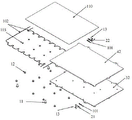
Fig. 3 is an exploded view of the top liquid cooling module of the blade power battery pack of the present invention.
Fig. 4 is an exploded view of the bottom liquid cooling module of the blade power battery pack of the present invention.
Fig. 5 is a schematic view of fig. 1 with parts of fig. 3 and 4 removed.
Fig. 6 is an exploded view of fig. 5.
Detailed Description
The invention will be further described with reference to the drawings and specific embodiments.
Example 1: as shown in fig. 1-6, a liquid-cooling phase-change composite cooling device for a blade power battery comprises a blade power battery pack, a housing 6, an upper liquid-cooling substrate 41, a lower liquid-cooling substrate 42, an upper liquid-cooling cover plate 31, and a lower liquid-cooling cover plate 32; the blade power battery pack is composed of a plurality of blade power batteries 7 which are arranged in parallel at intervals and placed inside a shell 6, grid-shaped baffles 5 are arranged on the left side and the right side of the shell 6, a phase change material 120 is vertically inserted into a gap of 3mm between every two adjacent blade power batteries 7, the width of each grid-shaped baffle 5 is larger than that of the gap between every two adjacent blade power batteries 7, two sides of each phase change material 120 and two sides of each blade power battery 7 are in contact with the grid-shaped baffles 5, electrodes on two sides of each blade power battery 7 are exposed out of the grid-shaped baffles 5, heat conducting silica gel 110 is arranged between each blade power battery pack and an upper liquid cooling substrate 41 above and a lower liquid cooling substrate 42 below, flow channel sealing gaskets 102 are arranged between each upper liquid cooling substrate 41 and an upper liquid cooling cover plate 31 above and between each lower liquid cooling substrate 42 and a lower liquid cooling cover plate 32 below, and fractal flow channels 82 are arranged on the inner side surfaces of each upper liquid cooling substrate 41 and each lower liquid cooling substrate 42, the inlet liquid cooling joint 21 is arranged at one corner of the front ends of the upper liquid cooling substrate 41 and the lower liquid cooling substrate 42, the outlet liquid cooling joint 22 is arranged at one corner of the diagonal line of the rear end of the upper liquid cooling substrate and the inlet liquid cooling joint 21, and the inlet liquid cooling joint 21 is communicated with the outlet liquid cooling joint 22 through the fractal runner 82.
Further, the fractal flow channel 82 includes a cooling inlet 81, a cooling outlet 87, and a first flow channel 83, a second flow channel 84, a third flow channel 85, and a fourth flow channel 86 connected in parallel, inlet ends of the first flow channel 83, the second flow channel 84, the third flow channel 85, and the fourth flow channel 86 are all communicated with the cooling inlet 81, outlet ends of the first flow channel 83, the second flow channel 84, the third flow channel 85, and the fourth flow channel 86 are all communicated with the cooling outlet 87, the cooling inlet 81 is connected with the inlet liquid cooling connector 21, the cooling outlet 87 is connected with the outlet liquid cooling connector 22, and each flow channel includes a first series flow channel 91, a second series flow channel 92, a third series flow channel 93, a fourth series flow channel 94, a fifth series flow channel 95, a sixth series flow channel 96, and a seventh series flow channel 97 which are communicated from top to bottom.
Furthermore, two sides of each series flow channel are uniformly provided with a flow disturbing device 98, and the flow disturbing devices 98 are cylindrical, rhombic or elliptical and the like and are used for enhancing the turbulence intensity of the cooling liquid.
Further, a flow passage peripheral gasket groove 104 is formed in the periphery of the fractal flow passage 82. The runner peripheral sealing gasket grooves 104 are distributed on the outer sides of the first-stage runner 83 and the fourth-stage runner 86 of the fractal runner 82, and the shape and the outline are similar to the outer edge outline of the first-stage runner 83 and the fourth-stage runner 86.
Further, the second screw 12 at the upper portion sequentially penetrates through the screw holes at the corresponding positions of the middle portions of the upper liquid cooling cover plate 31, the flow channel sealing gasket 102 at the upper portion and the upper liquid cooling base plate 41 from top to bottom to fixedly connect the upper liquid cooling cover plate 31, the flow channel sealing gasket 102 at the upper portion and the upper liquid cooling base plate 41, and the second screw 12 at the lower portion sequentially penetrates through the screw holes at the corresponding positions of the middle portions of the lower liquid cooling cover plate 32, the flow channel sealing gasket 102 at the lower portion and the lower liquid cooling base plate 42 from bottom to top to fixedly connect the lower liquid cooling cover plate, the flow channel sealing gasket 102 at the lower portion and the lower liquid cooling base plate 42. As shown in fig. 2, the middle screw holes on the upper liquid-cooling substrate 41 and the lower liquid-cooling substrate 42 are holes at the centers of the second series flow channel 92, the fourth series flow channel 94, and the sixth series flow channel 96, and a substrate screw gasket groove 105 is provided in the screw holes, for a total of 6 substrate screw gasket grooves 105. As shown in fig. 3 and 4, a flow channel center screw gasket 103 is provided in a screw hole in the middle of the flow channel gasket 102.
Furthermore, four corners of the front side plate and the rear side plate of the housing 6 are respectively provided with a housing boss with screw holes, the upper liquid cooling substrate 41, the lower liquid cooling substrate 42, the upper liquid cooling cover plate 31, the lower liquid cooling cover plate 32 and the housing boss are respectively provided with a connecting boss with screw holes at the corresponding position, the first screw 11 at the upper part sequentially penetrates through the connecting boss of the upper liquid cooling cover plate 31, the connecting boss of the upper liquid cooling substrate 41 and the housing boss at the upper part of the housing 6 from top to bottom to fixedly connect the three, and the first screw 11 at the lower part sequentially penetrates through the connecting boss of the lower liquid cooling cover plate 32, the connecting boss of the lower liquid cooling substrate 42 and the housing boss at the lower part of the housing 6 from bottom to top to fixedly connect the three.
Furthermore, the joints of the inlet liquid cooling joint 21 and the outlet liquid cooling joint 22 with the upper liquid cooling substrate 41 and the lower liquid cooling substrate 42 are all provided with liquid cooling joint sealing gaskets 101, and the inlet liquid cooling joint 21 and the outlet liquid cooling joint 22 are respectively connected with the upper liquid cooling substrate 41 and the lower liquid cooling substrate 42 through screws 13.
The flow channel gasket groove 104, the base plate screw gasket groove 105, the flow channel center screw gasket 103, the flow channel gasket 102, and the liquid cooling joint gasket 101 are used to prevent the leakage of the cooling liquid when the cooling liquid flows in the fractal flow channel 82.
Further, the housing 6 is welded integrally with the barrier 5.
Further, the upper liquid cooling substrate 41, the lower liquid cooling substrate 42, the upper liquid cooling cover plate 31, the lower liquid cooling cover plate 32, the housing 6, the grid-shaped baffle 5, the inlet liquid cooling connector 21 and the outlet liquid cooling connector 22 are all made of aluminum profiles.
The utility model discloses a theory of operation is: as shown in fig. 1, the upper liquid-cooled substrate 41 is connected with the inlet liquid-cooled joint 21 at the upper left side, the outlet liquid-cooled joint 22 at the lower right side, the lower liquid-cooled substrate 42 is connected with the inlet liquid-cooled joint 21 at the lower left side, and the outlet liquid-cooled joint 22 at the upper right side. The cooling liquid enters from the inlet liquid cooling connector 21, and respectively enters the first flow channel 83, the second flow channel 84, the third flow channel 85 and the fourth flow channel 86 which are connected in parallel through the cooling inlet 81, the cooling liquid passes through the first series flow channel 91, the second series flow channel 92, the third series flow channel 93, the fourth series flow channel 94, the fifth series flow channel 95, the sixth series flow channel 96 and the seventh series flow channel 97 in each parallel flow channel, and finally flows into the outlet liquid cooling connector 22 through the cooling outlet 87, so that the cooling circulation is completed, and the cooling liquid passes through the flow channels in the fractal flow channel 82 to exchange heat with the upper liquid cooling substrate 41 and the lower liquid cooling substrate 42.
The blade power battery 7 exchanges heat with the upper liquid-cooling substrate 41 and the lower liquid-cooling substrate 42 through the heat-conducting silica gel 110, and meanwhile, the heat-conducting silica gel 110 plays a role in buffering and heat conduction and ensures that the upper liquid-cooling substrate 41 and the lower liquid-cooling substrate 42 are tightly attached to the blade power battery 7, so that heat transfer resistance is small.
A 3mm gap is formed between every two blade power batteries 7, a phase-change material 120 with the thickness of 3mm is arranged in the gap, the phase-change material 120 is in surface contact with the blade power batteries 7, the phase-change material 120 has the characteristics of absorbing heat at high temperature and releasing heat at low temperature, when the temperature of the blade power batteries 7 is higher, the phase-change material 120 can absorb the heat generated by the blade power batteries 7, when the temperature reaches the phase-change temperature of the phase-change material 120, the phase-change material can change from solid state to liquid state, the heat generated by the blade power batteries 7 is stored in the phase-change material 120, the process can ensure the uniform temperature of the blade power batteries 7 and the service life of the batteries, because the phase-change material 120 is clamped between the blade power batteries 7, after the assembly is completed, the phase-change material 120 is covered by the grid-shaped baffle 5, the heat-conducting silica gel 110, the upper liquid-cooled substrate 41 and the lower liquid-cooled substrate 42, so that the phase-change material 120 cannot be seen from the outside, thereby preventing the phase change material 120 from leaking after heat absorption and melting.
The cooling liquid is generally a mixed liquid of ethylene glycol and water with the mass ratio of 1: 1, has good compatibility with aluminum, and can not be solidified at the low temperature of minus 40 ℃.
The cooling liquid flows in the fractal flow passage 82, and an external cooling pump (such as a water pump) is required to provide circulating power, so that the cooling liquid can flow in the fractal flow passage 82, and the flow speed of the cooling liquid can be controlled.
On one hand, heat generated by the blade power battery 7 is transmitted to the upper liquid cooling substrate 41 and the lower liquid cooling substrate 42 through the heat conducting silica gel 110 at the top and the bottom of the blade power battery 7, and cooling liquid circulates in the fractal flow channels 82 in the upper liquid cooling substrate 41 and the lower liquid cooling substrate 42, and exchanges heat with the upper liquid cooling substrate 41 and the lower liquid cooling substrate 42 to take away the heat. On the other hand, the heat generated by the blade power battery 7 is transferred to the phase-change material 120 in contact with the blade power battery 7, and the heat is stored in the phase-change material 120, so that the temperature of the blade power battery 7 is kept in a safe temperature range, the blade power battery can normally work, and the purpose of cooling by combining liquid cooling and phase change is achieved.
The foregoing is only a preferred embodiment of the present invention, and it should be noted that, for those skilled in the art, several modifications can be made without departing from the principle of the present invention, and these modifications should also be considered as the protection scope of the present invention.
Claims (10)
1. The utility model provides a blade power battery liquid cooling phase transition combined type cooling device which characterized in that: comprises a blade power battery pack, a shell (6), an upper liquid cooling base plate (41), a lower liquid cooling base plate (42), an upper liquid cooling cover plate (31) and a lower liquid cooling cover plate (32); the blade power battery pack is formed by arranging a plurality of blade power batteries (7) in parallel at intervals and is placed inside a shell (6), grid-shaped baffles (5) are arranged on the left side and the right side of the shell (6), phase change materials (120) are vertically inserted into gaps between every two adjacent blade power batteries (7), the width of each grid-shaped baffle (5) is larger than that of the gap between every two adjacent blade power batteries (7), two sides of each phase change material (120) and two sides of each blade power battery (7) are in contact with the grid-shaped baffles (5), electric stages on two sides of each blade power battery (7) are exposed out of the grid-shaped baffles (5), heat conducting silica gel (110) are arranged between each blade power battery pack and an upper liquid cooling substrate (41) above and a lower liquid cooling substrate (42) below, a flow channel sealing gasket (102) is arranged between each upper liquid cooling substrate (41) and an upper liquid cooling cover plate (31) above and between each lower liquid cooling substrate (42) and a lower liquid cooling cover plate (32) below, go up liquid cooling base plate (41), down liquid cooling base plate (42) medial surface all is equipped with fractal runner (82), goes up liquid cooling base plate (41), the one corner of liquid cooling base plate (42) front end down all is equipped with import liquid cooling joint (21), and the rear end all is equipped with export liquid cooling joint (22) with import liquid cooling joint (21) in diagonal one corner, and import liquid cooling joint (21) and export liquid cooling joint (22) are through fractal runner (82) intercommunication.
2. The blade power battery liquid-cooling phase-change composite cooling device of claim 1, characterized in that: the fractal runner (82) comprises a cooling inlet (81), a cooling outlet (87) and first runners (83) connected in parallel, a second runner (84), a third runner (85) and a fourth runner (86), the inlet ends of the first runner (83), the second runner (84), the third runner (85) and the fourth runner (86) are communicated with the cooling inlet (81), the outlet ends of the first runner (83), the second runner (84), the inlet ends of the third runner (85) and the fourth runner (86) are communicated with the cooling outlet (87), the cooling inlet (81) is connected with the inlet liquid cooling connector (21), the cooling outlet (87) is connected with the outlet liquid cooling connector (22), each runner comprises a first series runner (91), a second series runner (92), a third series runner (93), a fourth series runner (94), a fifth series runner (95), a sixth series runner (96) and a seventh series runner (97) which are communicated from top to bottom.
3. The blade power battery liquid-cooling phase-change composite cooling device of claim 2, characterized in that: and two sides of each series flow channel are uniformly provided with a flow disturbing device (98).
4. The blade power battery liquid-cooling phase-change composite cooling device of claim 3, characterized in that: the flow disturbing device (98) is cylindrical or rhombic or elliptic.
5. The blade power battery liquid-cooling phase-change composite cooling device of claim 1 or 2, characterized in that: and a runner peripheral sealing gasket groove (104) is formed in the periphery of the fractal runner (82).
6. The blade power battery liquid-cooling phase-change composite cooling device of claim 1, wherein: the second screw (12) at the upper part sequentially penetrates through the screw holes at the corresponding positions of the middle parts of the upper liquid cooling cover plate (31), the upper flow channel sealing gasket (102) and the upper liquid cooling base plate (41) from top to bottom to fixedly connect the upper liquid cooling cover plate, the upper flow channel sealing gasket and the upper liquid cooling base plate, and the second screw (12) at the lower part sequentially penetrates through the screw holes at the corresponding positions of the middle parts of the lower liquid cooling cover plate (32), the lower flow channel sealing gasket (102) and the lower liquid cooling base plate (42) from bottom to top to fixedly connect the upper liquid cooling cover plate, the upper flow channel sealing gasket and the upper liquid cooling base plate.
7. The blade power battery liquid-cooling phase-change composite cooling device of claim 1, characterized in that: all be equipped with the shell boss of taking the screw hole on four angles of curb plate around shell (6), go up liquid cooling base plate (41), lower liquid cooling base plate (42), go up liquid cooling apron (31), lower liquid cooling apron (32) all are equipped with the connection boss of taking the screw hole with shell boss corresponding department, the first screw (11) top-down of top passes the connection boss of going up liquid cooling apron (31) in proper order, the connection boss of going up liquid cooling base plate (41), the shell boss of shell (6) top is with three fixed connection, the first screw (11) of below passes the connection boss of lower liquid cooling apron (32) in proper order from bottom to top, the connection boss of lower liquid cooling base plate (42), the shell boss of shell (6) below is with three fixed connection.
8. The blade power battery liquid-cooling phase-change composite cooling device of claim 1, characterized in that: the joints of the inlet liquid cooling joint (21) and the outlet liquid cooling joint (22) with the upper liquid cooling substrate (41) and the lower liquid cooling substrate (42) are respectively provided with a liquid cooling joint sealing gasket (101), and the inlet liquid cooling joint (21) and the outlet liquid cooling joint (22) are respectively connected with the upper liquid cooling substrate (41) and the lower liquid cooling substrate (42) through screws (13).
9. The blade power battery liquid-cooling phase-change composite cooling device of claim 1, characterized in that: the shell (6) and the grid-shaped baffle (5) are welded into a whole.
10. The blade power battery liquid-cooling phase-change composite cooling device of claim 1, characterized in that: the upper liquid cooling substrate (41), the lower liquid cooling substrate (42), the upper liquid cooling cover plate (31), the lower liquid cooling cover plate (32), the shell (6), the grid-shaped baffle (5), the inlet liquid cooling connector (21) and the outlet liquid cooling connector (22) are all made of aluminum profiles.
Priority Applications (1)
| Application Number | Priority Date | Filing Date | Title |
|---|---|---|---|
| CN202221282733.5U CN217522115U (en) | 2022-05-26 | 2022-05-26 | Blade power battery liquid cooling phase transition combined type cooling device |
Applications Claiming Priority (1)
| Application Number | Priority Date | Filing Date | Title |
|---|---|---|---|
| CN202221282733.5U CN217522115U (en) | 2022-05-26 | 2022-05-26 | Blade power battery liquid cooling phase transition combined type cooling device |
Publications (1)
| Publication Number | Publication Date |
|---|---|
| CN217522115U true CN217522115U (en) | 2022-09-30 |
Family
ID=83389956
Family Applications (1)
| Application Number | Title | Priority Date | Filing Date |
|---|---|---|---|
| CN202221282733.5U Active CN217522115U (en) | 2022-05-26 | 2022-05-26 | Blade power battery liquid cooling phase transition combined type cooling device |
Country Status (1)
| Country | Link |
|---|---|
| CN (1) | CN217522115U (en) |
Cited By (2)
| Publication number | Priority date | Publication date | Assignee | Title |
|---|---|---|---|---|
| CN115498328A (en) * | 2022-11-07 | 2022-12-20 | 山东大学 | Semi-open type battery thermal management device coupled with battery surface |
| CN116885340A (en) * | 2023-09-06 | 2023-10-13 | 成都沃飞天驭科技有限公司 | Immersed battery module and thermal management system thereof |
-
2022
- 2022-05-26 CN CN202221282733.5U patent/CN217522115U/en active Active
Cited By (3)
| Publication number | Priority date | Publication date | Assignee | Title |
|---|---|---|---|---|
| CN115498328A (en) * | 2022-11-07 | 2022-12-20 | 山东大学 | Semi-open type battery thermal management device coupled with battery surface |
| CN116885340A (en) * | 2023-09-06 | 2023-10-13 | 成都沃飞天驭科技有限公司 | Immersed battery module and thermal management system thereof |
| CN116885340B (en) * | 2023-09-06 | 2023-11-28 | 成都沃飞天驭科技有限公司 | Immersed battery module and thermal management system thereof |
Similar Documents
| Publication | Publication Date | Title |
|---|---|---|
| CN217522115U (en) | Blade power battery liquid cooling phase transition combined type cooling device | |
| CN202217748U (en) | Battery heat radiation device and battery pack | |
| CN211879557U (en) | Liquid cooling plate | |
| CN111540858B (en) | New energy automobile battery system capable of efficiently dissipating heat | |
| CN110165332B (en) | Concentrated radiating group battery heat abstractor | |
| CN216903105U (en) | Square shell and square battery | |
| CN114583326A (en) | Energy storage battery module, liquid cooling plate and liquid cooling plate combination | |
| CN108075081A (en) | Battery pack, battery pack and the vehicle with the battery pack | |
| WO2024021481A1 (en) | Liquid cooling plate and battery pack | |
| CN111403847B (en) | Power battery tab heat dissipation system based on coupling of phase change material and U-shaped flat heat pipe | |
| CN207834518U (en) | Radiator and battery case | |
| CN211182447U (en) | Liquid cooling plate | |
| CN210120214U (en) | Power battery heat abstractor | |
| CN116454461A (en) | Battery pack | |
| EP4273996A1 (en) | Battery cell and battery module comprising same | |
| CN214378603U (en) | Heat management device for lithium ion battery of electric vehicle | |
| CN210430028U (en) | Battery cooling device and power battery box | |
| CN113178638A (en) | Bionic heat dissipation method and device for liquid-cooled battery pack | |
| CN216250869U (en) | Heat dissipation module for lithium battery of electric automobile | |
| CN220341310U (en) | Battery pack capable of uniformly radiating and liquid cooling structure thereof | |
| CN219476803U (en) | Battery pack with cooling water channel and vehicle using battery pack | |
| CN218069983U (en) | Temperature-equalizing energy-storage liquid cooling plate | |
| CN212695223U (en) | High-rate battery module | |
| CN217509345U (en) | Power module device and vehicle | |
| CN215377513U (en) | Square power battery pack with heat dissipation and preheating structure |
Legal Events
| Date | Code | Title | Description |
|---|---|---|---|
| GR01 | Patent grant | ||
| GR01 | Patent grant |