CN217469027U - Plug and socket assembly - Google Patents
Plug and socket assembly Download PDFInfo
- Publication number
- CN217469027U CN217469027U CN202221118051.0U CN202221118051U CN217469027U CN 217469027 U CN217469027 U CN 217469027U CN 202221118051 U CN202221118051 U CN 202221118051U CN 217469027 U CN217469027 U CN 217469027U
- Authority
- CN
- China
- Prior art keywords
- plug
- socket
- slot
- clamping
- assembly
- Prior art date
- Legal status (The legal status is an assumption and is not a legal conclusion. Google has not performed a legal analysis and makes no representation as to the accuracy of the status listed.)
- Active
Links
- 238000003825 pressing Methods 0.000 claims description 26
- 238000003780 insertion Methods 0.000 claims description 8
- 230000006835 compression Effects 0.000 claims description 7
- 238000007906 compression Methods 0.000 claims description 7
- 230000000712 assembly Effects 0.000 claims description 6
- 238000000429 assembly Methods 0.000 claims description 6
- 230000037431 insertion Effects 0.000 claims description 6
- 230000000149 penetrating effect Effects 0.000 claims 1
- 238000009434 installation Methods 0.000 abstract description 5
- 239000000463 material Substances 0.000 abstract description 5
- 230000006978 adaptation Effects 0.000 abstract description 3
- 230000005611 electricity Effects 0.000 abstract description 3
- 239000012634 fragment Substances 0.000 description 2
- 230000003044 adaptive effect Effects 0.000 description 1
- 238000005452 bending Methods 0.000 description 1
- 238000010586 diagram Methods 0.000 description 1
- 230000006872 improvement Effects 0.000 description 1
- 238000002347 injection Methods 0.000 description 1
- 239000007924 injection Substances 0.000 description 1
- 210000001503 joint Anatomy 0.000 description 1
- 238000004519 manufacturing process Methods 0.000 description 1
- 230000004048 modification Effects 0.000 description 1
- 238000012986 modification Methods 0.000 description 1
- 230000008707 rearrangement Effects 0.000 description 1
- 238000006467 substitution reaction Methods 0.000 description 1
- 230000000007 visual effect Effects 0.000 description 1
Images


Classifications
-
- H—ELECTRICITY
- H01—ELECTRIC ELEMENTS
- H01R—ELECTRICALLY-CONDUCTIVE CONNECTIONS; STRUCTURAL ASSOCIATIONS OF A PLURALITY OF MUTUALLY-INSULATED ELECTRICAL CONNECTING ELEMENTS; COUPLING DEVICES; CURRENT COLLECTORS
- H01R13/00—Details of coupling devices of the kinds covered by groups H01R12/70 or H01R24/00 - H01R33/00
- H01R13/40—Securing contact members in or to a base or case; Insulating of contact members
-
- H—ELECTRICITY
- H01—ELECTRIC ELEMENTS
- H01R—ELECTRICALLY-CONDUCTIVE CONNECTIONS; STRUCTURAL ASSOCIATIONS OF A PLURALITY OF MUTUALLY-INSULATED ELECTRICAL CONNECTING ELEMENTS; COUPLING DEVICES; CURRENT COLLECTORS
- H01R13/00—Details of coupling devices of the kinds covered by groups H01R12/70 or H01R24/00 - H01R33/00
- H01R13/62—Means for facilitating engagement or disengagement of coupling parts or for holding them in engagement
- H01R13/627—Snap or like fastening
-
- H—ELECTRICITY
- H01—ELECTRIC ELEMENTS
- H01R—ELECTRICALLY-CONDUCTIVE CONNECTIONS; STRUCTURAL ASSOCIATIONS OF A PLURALITY OF MUTUALLY-INSULATED ELECTRICAL CONNECTING ELEMENTS; COUPLING DEVICES; CURRENT COLLECTORS
- H01R13/00—Details of coupling devices of the kinds covered by groups H01R12/70 or H01R24/00 - H01R33/00
- H01R13/62—Means for facilitating engagement or disengagement of coupling parts or for holding them in engagement
- H01R13/629—Additional means for facilitating engagement or disengagement of coupling parts, e.g. aligning or guiding means, levers, gas pressure electrical locking indicators, manufacturing tolerances
- H01R13/631—Additional means for facilitating engagement or disengagement of coupling parts, e.g. aligning or guiding means, levers, gas pressure electrical locking indicators, manufacturing tolerances for engagement only
-
- H—ELECTRICITY
- H01—ELECTRIC ELEMENTS
- H01R—ELECTRICALLY-CONDUCTIVE CONNECTIONS; STRUCTURAL ASSOCIATIONS OF A PLURALITY OF MUTUALLY-INSULATED ELECTRICAL CONNECTING ELEMENTS; COUPLING DEVICES; CURRENT COLLECTORS
- H01R24/00—Two-part coupling devices, or either of their cooperating parts, characterised by their overall structure
Abstract
The utility model belongs to the technical field of binding post, a plug and socket subassembly is disclosed, plug and socket subassembly includes plug and socket, and the socket can peg graft mutually with the plug, and the plug is the first plug or the second plug of structure difference, and the socket is equipped with the slot that can hold the plug, is provided with one row at least contact pin in the slot, and when the plug was pegged graft in the slot, the contact pin can be connected with the plug electricity. The utility model provides a plug and socket subassembly, every plug homoenergetic is pegged graft with the slot of socket and is connected with the contact pin electricity, makes a socket can a plurality of plugs of adaptation, and then makes socket simplification, practices thrift cost such as manual work, mould, material, and the convenience of on-the-spot installation improves greatly.
Description
Technical Field
The utility model relates to a binding post technical field especially relates to a plug and socket subassembly.
Background
The terminal is an accessory product for realizing electrical connection, and is industrially classified into the category of connectors. With higher and higher industrial automation degree and stricter and more accurate industrial control requirements, the use amount of the wiring terminal gradually increases. With the development of the electronic industry, the use range of the connecting terminal is more and more, and the types of the connecting terminal are more and more.
The plug and the socket of the existing wiring terminal with various types and various types are not adaptive, so that the material number of the wiring terminal product is large, the production process is complicated, and the cost of manpower, a mold, materials and the like is correspondingly increased.
SUMMERY OF THE UTILITY MODEL
An object of the utility model is to provide a plug and socket subassembly, socket can the multiple plug of adaptation.
To achieve the purpose, the utility model adopts the following technical proposal:
a plug and socket assembly comprises a plug and a socket, wherein the socket can be connected with the plug in an inserting mode, the plug is a first plug or a second plug which are different in structure, the socket is provided with a slot capable of containing the plug, at least one row of contact pins are arranged in the slot, and when the plug is connected in the slot in an inserting mode, the contact pins can be electrically connected with the plug.
Optionally, the two inner side walls opposite to the slot are provided with clamping grooves, the outer side wall of the plug is provided with buckles in one-to-one correspondence with the clamping grooves, and when the plug is inserted into the slot, the buckles are clamped with the clamping grooves.
Optionally, the buckle includes the joint board, be provided with on the joint board can with the joint arch of draw-in groove joint, the one end of joint board with the lateral wall elastic connection of plug, the other end of joint board is provided with presses the splenium.
Optionally, at least one guide protrusion is arranged in the slot, the plug is provided with at least one guide groove corresponding to the guide protrusion, and when the plug is in butt joint with the slot, the guide protrusion can be arranged in the guide groove and slide along the extending direction of the guide groove.
Optionally, the first plug is a press-fit plug, and the second plug is an in-line plug.
Optionally, the compression joint type plug comprises at least one row of compression joint terminals which can be inserted into and electrically connected with the contact pins, and the compression joint terminals are arranged in one-to-one correspondence with the contact pins.
Optionally, the direct-insertion plug comprises at least one row of conductive pieces capable of being inserted into and electrically connected with the contact pins and elastic piece assemblies arranged in one-to-one correspondence with the conductive pieces, the conductive pieces are arranged in one-to-one correspondence with the contact pins, and the elastic piece assemblies are used for fixing wires and enabling the wires to be electrically connected with the conductive pieces.
Optionally, the dome assembly comprises:
the elastic sheet is fixed in the direct-insertion plug;
the key is connected with the direct-insert plug in a sliding mode, the first end of the key penetrates through the direct-insert plug and abuts against the elastic sheet, and the deformation of the elastic sheet is changed by sliding the key so as to fix or release the wire.
Optionally, the formula plug that cut straightly has seted up at least one row of mounting groove, the second perforates and the spout, the second perforate with the spout all with the mounting groove one-to-one intercommunication sets up, electrically conductive piece with the shell fragment is all arranged in the mounting groove, the button wear to locate in the spout and with spout sliding connection.
Optionally, a pressing plate is arranged at the first end of the conductive piece, and the elastic piece assembly can fix the lead on the pressing plate;
the second end of the conductive piece is provided with a clamping opening, and the contact pin can be inserted into the clamping opening.
The utility model has the advantages that:
the utility model provides a plug and socket subassembly, every plug homoenergetic is pegged graft with the slot of socket and is connected with the contact pin electricity, makes a socket can a plurality of plugs of adaptation, and then makes socket simplification, practices thrift cost such as manual work, mould, material, and the convenience of on-the-spot installation improves greatly.
Drawings
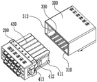
Fig. 1 is an exploded schematic view of a press-fit plug and a socket provided by the present invention;
fig. 2 is an exploded schematic view of an in-line plug and socket provided by the present invention;
fig. 3 is a schematic view illustrating a visual angle connection between the press-fit plug and the socket provided by the present invention;
fig. 4 is a schematic view illustrating a direct plug-in type plug and a socket according to the present invention;
fig. 5 is a schematic view of the compression-type plug and the socket according to another perspective of the present invention;
fig. 6 is a schematic diagram illustrating another perspective plugging of an in-line plug and a socket provided by the present invention;
fig. 7 is a cross-sectional view of a compression-type plug and socket provided by the present invention;
fig. 8 is a schematic structural view of a crimp terminal provided by the present invention;
fig. 9 is a cross-sectional view of an in-line plug and socket provided by the present invention;
fig. 10 is an enlarged schematic view of a in fig. 9 according to the present invention.
In the figure:
100. a crimp-style plug; 101. a first perforation; 102. a stopper portion; 103. a first plug end face; 110. a crimp terminal; 111. a wiring pressing sheet; 112. inserting holes;
200. a direct plug; 201. mounting grooves; 202. a second perforation; 203. a chute; 204. a third perforation; 205. a second plug end face; 210. a conductive member; 211. pressing a plate; 2111. a groove; 212. clamping the opening; 220. a spring plate assembly; 221. a spring plate; 222. pressing a key; 2221. pressing the groove;
300. a socket; 310. inserting slots; 311. inserting a pin; 312. a card slot; 320. a first reference numeral; 330. a guide projection; 340. a clamping part;
410. buckling; 411. a clamping and connecting plate; 412. clamping the bulges; 413. a pressing part; 420. a second reference numeral; 430. a guide groove.
Detailed Description
The present invention will be described in further detail with reference to the accompanying drawings and examples. It is to be understood that the specific embodiments described herein are merely illustrative of the invention and are not limiting of the invention. It should be further noted that, for the convenience of description, only some of the structures related to the present invention are shown in the drawings, not all of the structures.
In the description of the present invention, unless expressly stated or limited otherwise, the terms "connected," "connected," and "fixed" are to be construed broadly, e.g., as meaning permanently connected, detachably connected, or integral to one another; can be mechanically or electrically connected; either directly or indirectly through intervening media, either internally or in any other relationship. The specific meaning of the above terms in the present invention can be understood as a specific case by those skilled in the art.
In the present disclosure, unless expressly stated or limited otherwise, the first feature "on" or "under" the second feature may comprise direct contact between the first and second features, or may comprise contact between the first and second features not directly. Also, the first feature being "on," "above" and "over" the second feature includes the first feature being directly on and obliquely above the second feature, or merely indicating that the first feature is at a higher level than the second feature. A first feature being "under," "below," and "beneath" a second feature includes the first feature being directly under and obliquely below the second feature, or simply meaning that the first feature is at a lesser elevation than the second feature.
In the description of the present embodiment, the terms "upper", "lower", "right", etc. are used in an orientation or positional relationship based on that shown in the drawings only for convenience of description and simplicity of operation, and do not indicate or imply that the device or element referred to must have a particular orientation, be constructed and operated in a particular orientation, and thus, should not be construed as limiting the present invention. Furthermore, the terms "first" and "second" are used only for descriptive purposes and are not intended to have a special meaning.
Referring to fig. 1 to 2, the present embodiment provides a plug and socket assembly, a plug and a socket 300, the socket 300 can be plugged with the plug, the plug is a first plug or a second plug with different structures, the socket 300 is provided with a slot 310 capable of accommodating the plug, at least one row of pins 311 is arranged in the slot 310, and when the plug is plugged in the slot 310, the pins 311 can be electrically connected with the plug.
In this embodiment, each plug can be plugged into the slot 310 of the socket 300 and electrically connected to the pin 311, so that one socket 300 can be adapted to multiple plugs, and further the socket 300 is simplified, thereby saving the cost of labor, mold, material and the like, and greatly improving the convenience of field installation.
Preferably, two rows of pins 311 are provided within the socket 300.
In this embodiment, the two opposite inner side walls of the slot 310 are both provided with the slots 312, the outer side wall of the plug is provided with the buckles 410 corresponding to the slots 312 one by one, and when the plug is plugged into the slot 310, the buckles 410 are connected with the slots 312 in a clamped manner, so that the plug is fixedly connected with the socket 300, the plug is prevented from being separated from the socket 300 due to an unexpected situation, and the stability of the electrical connection between the plug and the socket 300 is improved.
Specifically, buckle 410 includes joint plate 411, is provided with the joint arch 412 that can with draw-in groove 312 joint on the joint plate 411, and the one end of joint plate 411 and the lateral wall elastic connection of plug, the other end of joint plate 411 are provided with and press the splenium 413. In this embodiment, when the plug is separated from the slot 310, the pressing portion 413 is pressed, and the clamping plate 411 is elastically bent, so that the buckle 410 is separated from the clamping groove 312, and the plug can be pulled out from the slot 310.
Further, the snap 410 and the plug may be, but are not limited to being, integrally injection molded.
In this embodiment, at least one guiding protrusion 330 is disposed in the slot 310, the plug is provided with at least one guiding groove 430 corresponding to the guiding protrusion 330, when the plug is mated with the slot 310, the guiding protrusion 330 can be disposed in the guiding groove 430 and slide along the extending direction of the guiding groove 430, so as to have a guiding function, and further, the plug can be precisely mated with the slot 310.
In the present embodiment, referring to fig. 3 to 4, a first label 320 corresponding to the pin 311 is disposed on an outer sidewall of the socket 300, and a second label 420 corresponding to the first label 320 is disposed on an outer sidewall of the plug, the second label 420 has a function of guiding a wire connection, so that when the plug is plugged into the socket 300, the occurrence of reverse plugging can be effectively avoided.
Specifically, as shown in fig. 5 to 6, a clamping portion 340 is disposed on an outer wall of one side of the socket 300, and the clamping portion 340 is fixedly connected with an external component, so as to facilitate installation of the socket 300.
Preferably, the plug may be a crimp plug 100 or an in-line plug 200.
In the present embodiment, referring to fig. 7 to 8, the press-fit plug 100 includes at least one row of press-fit terminals 110 capable of being plugged and electrically connected with the pins 311, and the press-fit terminals 110 are disposed in one-to-one correspondence with the pins 311. Furthermore, the crimp-type plug 100 is provided with at least one row of first through holes 101, and the crimp terminal 110 is disposed in the first through holes 101, so that the structure is simple, and the installation of the crimp terminal 110 is convenient.
Specifically, a first end of the crimp terminal 110 is provided with a wiring pressing piece 111, a second end of the crimp terminal 110 is provided with a plugging hole 112, the wiring pressing piece 111 can be bent and crimped to fix a conducting wire, and the contact pin 311 can be plugged into the plugging hole 112. In the present embodiment, the wire is first fixed to the crimp terminal 110 by bending the wire pressing piece 111, and then the second end of the crimp terminal 110 is inserted toward the first through hole 101 to complete the assembly of the crimp-type plug 100 with the wire, facilitating the wire assembly.
Specifically, the stopper portion 102 is disposed in the first through hole 101, and when the crimp terminal 110 is disposed in the first through hole 101, the stopper portion 102 can stop the movement of the crimp terminal 110, so as to fix the crimp terminal 110 in the first through hole 101.
Specifically, the end of the insertion hole 112, which is located at the insertion end of the press-fit plug 100, is provided with a first insertion end surface 103 inclined inward, and the first insertion end surface 103 has a guiding function, so that the jamming of the press-fit plug 100 and the socket 300 is effectively prevented.
In this embodiment, referring to fig. 9 to 10, the in-line plug 200 includes at least one row of conductive members 210 capable of being inserted into and electrically connected to the pins 311 and elastic sheet assemblies 220 arranged in one-to-one correspondence with the conductive members 210, the conductive members 210 are arranged in one-to-one correspondence with the pins 311, and the elastic sheet assemblies 220 are used for fixing the wires and electrically connecting the wires to the conductive members 210, so that the structure is simple and the assembly between the in-line plug 200 and the wires is convenient.
Specifically, the elastic sheet assembly 220 includes an elastic sheet 221 and a key 222, the elastic sheet 221 is fixed in the in-line plug 200, the key 222 is slidably connected with the in-line plug 200, a first end of the key 222 penetrates through the in-line plug 200 and abuts against the elastic sheet 221, deformation of the elastic sheet 221 is changed through the sliding key 222 to fix or release the wire, and the wiring operation is convenient.
Further, the formula plug 200 that cut straightly has seted up at least one row of mounting groove 201, second and has perforated 202 and spout 203, and the second is perforated 202 and spout 203 and all communicates the setting with mounting groove 201 one-to-one, and electrically conductive piece 210 and shell fragment 221 all arrange mounting groove 201 in, and the button 222 wears to locate in the spout 203 and with spout 203 sliding connection, and then make this formula plug 200 that cut straightly simple structure compact.
Specifically, the second end of the key 222 is provided with a pressing groove 2221, and the pressing groove 2221 can be pressed by a screwdriver or other suitable tools, so that the key 222 moves towards the mounting groove 201, and the key 222 presses the elastic piece 221, so that the elastic piece 221 is far away from the conductive piece 210, and the wire is released.
Further, a pressing plate 211 is disposed at a first end of the conductive member 210, and the elastic piece assembly 220 can fix the conductive wire on the pressing plate 211, so that the conductive wire is electrically connected to the conductive member 210. In this embodiment, pressing the key 222 deforms the elastic piece 221, the elastic piece 221 is away from the pressing plate 211, the conductive wire penetrates through the second through hole 202 and is disposed between the elastic piece 221 and the pressing plate 211, and releasing the key 222 allows the elastic piece 221 to recover the deformation and press the conductive wire onto the pressing plate 211, so that the conductive wire is fixed, and the conductive wire is electrically connected to the conductive member 210.
Furthermore, a plurality of grooves 2111 are formed in one side of the pressing plate 211 facing the elastic sheet 221 at intervals, when the elastic sheet 221 presses the wire onto the pressing plate 211, at least a portion of the wire is deformed and placed in the grooves 2111, and the acting force between the pressing plate 211 and the elastic sheet 221 and the wire is increased, so that the wire is pressed between the pressing plate 211 and the elastic sheet 221 more stably.
Furthermore, a second end of the conductive member 210 is provided with a clamping opening 212, and the contact pin 311 can be inserted into the clamping opening 212. Specifically, a third through hole 204 is formed in the bottom of each mounting groove 201, and when the direct plug 200 is plugged into the socket 300, the pin 311 is inserted into the third through hole 204 and placed in the clamping opening 212, and is clamped by two side arms of the clamping opening 212, so that the direct plug 200 is conducted with the socket 300.
Specifically, the end of the third through hole 204, which is located at the plugging end of the in-line plug 200, is provided with a second plugging end surface 205 which is inclined inward, and the second plugging end surface 205 has a guiding function, so that the occurrence of jamming when the in-line plug 200 is plugged into the socket 300 is effectively prevented.
As a further application of the present invention, the plug may also be a screw connector plug or a wire-stripping-free plug (these two plugs will not be described herein).
It is obvious that the above embodiments of the present invention are only examples for clearly illustrating the present invention, and are not intended to limit the embodiments of the present invention. Numerous obvious variations, rearrangements and substitutions will now occur to those skilled in the art without departing from the scope of the invention. And are neither required nor exhaustive of all embodiments. Any modification, equivalent replacement, and improvement made within the spirit and principle of the present invention should be included in the protection scope of the claims of the present invention.
Claims (10)
1. A plug and receptacle assembly, comprising: the plug comprises a plug and a socket (300), the socket (300) can be plugged with the plug, the plug is a first plug or a second plug with different structures, the socket (300) is provided with a slot (310) capable of containing the plug, at least one row of contact pins (311) are arranged in the slot (310), and when the plug is plugged in the slot (310), the contact pins (311) can be electrically connected with the plug.
2. The plug and socket assembly of claim 1, wherein the two opposite inner side walls of the slot (310) are provided with a clamping groove (312), the outer side walls of the plug are provided with a snap (410) corresponding to the clamping groove (312) one by one, and when the plug is plugged into the slot (310), the snap (410) is clamped with the clamping groove (312).
3. The plug and socket assembly according to claim 2, wherein the buckle (410) comprises a clamping plate (411), a clamping protrusion (412) capable of clamping with the clamping groove (312) is arranged on the clamping plate (411), one end of the clamping plate (411) is elastically connected with the outer side wall of the plug, and a pressing part (413) is arranged at the other end of the clamping plate (411).
4. The plug and socket assembly of claim 1, wherein at least one guiding protrusion (330) is disposed in the insertion slot (310), the plugs are each provided with at least one guiding groove (430) corresponding to the guiding protrusion (330), and when the plugs are mated with the insertion slot (310), the guiding protrusions (330) can be disposed in the guiding grooves (430) and slide along the extending direction of the guiding grooves (430).
5. The plug and receptacle assembly of claim 1, wherein the first plug is a compression plug (100) and the second plug is an in-line plug (200).
6. The plug and socket assembly of claim 5, wherein said compression connector (100) comprises at least one row of compression terminals (110) capable of plugging and electrically connecting with said pins (311), said compression terminals (110) being arranged in one-to-one correspondence with said pins (311).
7. The plug and socket assembly of claim 5, wherein the in-line plug (200) comprises at least one row of conductive members (210) capable of being plugged and electrically connected with the pins (311) and spring assemblies (220) arranged in one-to-one correspondence with the conductive members (210), the conductive members (210) are arranged in one-to-one correspondence with the pins (311), and the spring assemblies (220) are used for fixing and electrically connecting the wires with the conductive members (210).
8. The plug and receptacle assembly of claim 7, wherein the spring assembly (220) comprises:
the elastic sheet (221), the elastic sheet (221) is fixed in the direct plug (200);
the key (222) is connected with the direct-insert plug (200) in a sliding mode, the first end of the key (222) penetrates through the direct-insert plug (200) and abuts against the elastic sheet (221), and the deformation of the elastic sheet (221) is changed by sliding the key (222) so as to fix or release the conducting wire.
9. The plug and socket assembly according to claim 8, wherein the in-line plug (200) is provided with at least one row of mounting grooves (201), second through holes (202) and sliding grooves (203), the second through holes (202) and the sliding grooves (203) are correspondingly communicated with the mounting grooves (201) one by one, the conductive pieces (210) and the elastic pieces (221) are arranged in the mounting grooves (201), and the keys (222) are arranged in the sliding grooves (203) in a penetrating manner and are connected with the sliding grooves (203) in a sliding manner.
10. The plug and socket assembly of claim 7, wherein the first end of the conductive member (210) is provided with a pressing plate (211), and the spring assembly (220) can fix the conductive wire on the pressing plate (211);
the second end of the conductive piece (210) is provided with a clamping opening (212), and the contact pin (311) can be inserted into the clamping opening (212).
Priority Applications (2)
| Application Number | Priority Date | Filing Date | Title |
|---|---|---|---|
| CN202221118051.0U CN217469027U (en) | 2022-05-10 | 2022-05-10 | Plug and socket assembly |
| PCT/CN2023/093199 WO2023217176A1 (en) | 2022-05-10 | 2023-05-10 | Plug and socket assembly |
Applications Claiming Priority (1)
| Application Number | Priority Date | Filing Date | Title |
|---|---|---|---|
| CN202221118051.0U CN217469027U (en) | 2022-05-10 | 2022-05-10 | Plug and socket assembly |
Publications (1)
| Publication Number | Publication Date |
|---|---|
| CN217469027U true CN217469027U (en) | 2022-09-20 |
Family
ID=83272542
Family Applications (1)
| Application Number | Title | Priority Date | Filing Date |
|---|---|---|---|
| CN202221118051.0U Active CN217469027U (en) | 2022-05-10 | 2022-05-10 | Plug and socket assembly |
Country Status (2)
| Country | Link |
|---|---|
| CN (1) | CN217469027U (en) |
| WO (1) | WO2023217176A1 (en) |
Cited By (1)
| Publication number | Priority date | Publication date | Assignee | Title |
|---|---|---|---|---|
| WO2023217176A1 (en) * | 2022-05-10 | 2023-11-16 | 菲尼克斯亚太电气(南京)有限公司 | Plug and socket assembly |
Families Citing this family (1)
| Publication number | Priority date | Publication date | Assignee | Title |
|---|---|---|---|---|
| CN117638570B (en) * | 2024-01-26 | 2024-04-09 | 广东乾威精密连接器有限公司 | Contact type battery connector |
Family Cites Families (6)
| Publication number | Priority date | Publication date | Assignee | Title |
|---|---|---|---|---|
| DE19807058A1 (en) * | 1998-02-19 | 1999-08-26 | Grote & Hartmann | Plastics plug connector casing with locking mechanism |
| DE10012324B4 (en) * | 2000-03-14 | 2005-08-11 | Fci Automotive Deutschland Gmbh | connector system |
| CN102157818B (en) * | 2010-12-24 | 2012-11-14 | 四川华丰企业集团有限公司 | Fast wiring interlocking electrical connector |
| DE202013105944U1 (en) * | 2013-12-26 | 2014-01-22 | Wago Verwaltungsgesellschaft Mbh | Spring-loaded terminal connection and connectors hereby |
| CN113161823A (en) * | 2021-03-30 | 2021-07-23 | 深圳市珺连电子有限公司 | 1.25mm double-row buckle connector |
| CN217469027U (en) * | 2022-05-10 | 2022-09-20 | 菲尼克斯亚太电气(南京)有限公司 | Plug and socket assembly |
-
2022
- 2022-05-10 CN CN202221118051.0U patent/CN217469027U/en active Active
-
2023
- 2023-05-10 WO PCT/CN2023/093199 patent/WO2023217176A1/en unknown
Cited By (1)
| Publication number | Priority date | Publication date | Assignee | Title |
|---|---|---|---|---|
| WO2023217176A1 (en) * | 2022-05-10 | 2023-11-16 | 菲尼克斯亚太电气(南京)有限公司 | Plug and socket assembly |
Also Published As
| Publication number | Publication date |
|---|---|
| WO2023217176A1 (en) | 2023-11-16 |
Similar Documents
| Publication | Publication Date | Title |
|---|---|---|
| CN217469027U (en) | Plug and socket assembly | |
| US7217158B2 (en) | Electrical connector | |
| EP1562262B1 (en) | A connector and a method of mounting it to an electric device | |
| US8876543B2 (en) | Connector | |
| US6817887B2 (en) | Insulation displacement connection connector having improved latch member | |
| CN111585062A (en) | Novel wiring terminal | |
| US20190363476A1 (en) | Electrical connector and connector assembly having the same | |
| EP1225656B1 (en) | Electrical connector assembly | |
| EP1385232A2 (en) | Electrical connector assembly, plug connector and receptacle connector | |
| EP0662734A1 (en) | Circuit board electrical connector | |
| CN210628525U (en) | Multi-compatible direct-insertion type quick connector | |
| CN211320403U (en) | Connector with elastic sheet contact | |
| US7980864B2 (en) | Connector for flexible printed circuit board | |
| CN210866692U (en) | Low-height connector | |
| CN111585094A (en) | Wire harness connector structure | |
| CN108615983B (en) | Wiring device of push switch | |
| CN216413301U (en) | Button type quick wiring terminal | |
| CN214589333U (en) | Novel direct-insert wiring structure | |
| CN215816629U (en) | Wire end connector | |
| JP5737446B1 (en) | Electrical connector mating structure | |
| CN217485786U (en) | Power supply female socket | |
| CN115939869B (en) | FPC connector assembly | |
| CN214849107U (en) | Front direct insertion type wiring terminal | |
| CN219163756U (en) | Plug connector | |
| CN215266744U (en) | FPC flexible board electric connector |
Legal Events
| Date | Code | Title | Description |
|---|---|---|---|
| GR01 | Patent grant | ||
| GR01 | Patent grant |