CN217464692U - Connecting piece of light-duty assembled support - Google Patents
Connecting piece of light-duty assembled support Download PDFInfo
- Publication number
- CN217464692U CN217464692U CN202220836837.XU CN202220836837U CN217464692U CN 217464692 U CN217464692 U CN 217464692U CN 202220836837 U CN202220836837 U CN 202220836837U CN 217464692 U CN217464692 U CN 217464692U
- Authority
- CN
- China
- Prior art keywords
- connecting piece
- pin
- supporting
- elastic pin
- screw rod
- Prior art date
- Legal status (The legal status is an assumption and is not a legal conclusion. Google has not performed a legal analysis and makes no representation as to the accuracy of the status listed.)
- Active
Links
- 208000017740 grade III prostatic intraepithelial neoplasia Diseases 0.000 claims description 11
- 230000035939 shock Effects 0.000 description 3
- 238000003466 welding Methods 0.000 description 3
- 230000003139 buffering effect Effects 0.000 description 2
- 238000006073 displacement reaction Methods 0.000 description 2
- 238000010586 diagram Methods 0.000 description 1
- 238000009434 installation Methods 0.000 description 1
- 230000003993 interaction Effects 0.000 description 1
- 210000001503 joint Anatomy 0.000 description 1
- 230000003014 reinforcing effect Effects 0.000 description 1
- 238000006467 substitution reaction Methods 0.000 description 1
Images


Landscapes
- Mutual Connection Of Rods And Tubes (AREA)
Abstract
The utility model provides a connecting piece of a light-duty assembled support, which comprises a supporting connecting piece for supporting a transverse supporting beam and a longitudinal connecting beam, and a first movable connecting piece for connecting the longitudinal connecting beam and the transverse supporting beam, wherein two ends of the supporting connecting piece are respectively connected with the transverse supporting beam and the longitudinal connecting beam through a second movable connecting piece and a third movable connecting piece; the utility model discloses an aspect, its cooperation through the pinhole can realize dismantling fast and install, has improved the convenience of use with the transportation, and on the other hand because elasticity pin one, elasticity pin two possess certain elasticity with elasticity pin three itself to can cushion the vibrations of tie point, thereby prevent that the off-premises station operation from shaking the damage to the connecting piece, improved the security.
Description
Technical Field
The utility model relates to an antidetonation support technical field, in particular to connecting piece of light-duty assembled support.
Background
The anti-seismic support limits the displacement of the attached electromechanical engineering facilities, controls the vibration of the facilities and transmits the load to various components or devices on the bearing structure.
When the outdoor unit of the air conditioner is installed, the outdoor unit of the air conditioner adopts a longitudinal connecting beam connected with a wall, a transverse supporting beam used for installing the outdoor unit and a reinforcing supporting rib structure connected between the longitudinal connecting beam and the transverse supporting beam.
Among traditional air conditioner leg joint spare, adopt welding or bolt fastening mostly, on the one hand, when adopting welding and bolt fastening, whole support is constituteed and is stabilized the triangle-shaped structure, and its shock attenuation shock-absorbing capacity is lower, and the connecting piece easily reaches fatigue limit and loses efficacy, and on the other hand, when adopting welding fastening, its support is a whole, and the space that occupies is great, and the convenience is lower in the transportation storage.
For this purpose, a connecting element for a lightweight fabricated support is proposed.
SUMMERY OF THE UTILITY MODEL
In view of the above, it is desirable to provide a connector for a lightweight fabricated stent that solves or alleviates the problems of the prior art, and at least provides a useful choice.
The embodiment of the utility model provides a technical scheme is so realized: the connecting piece of the light-duty assembled support comprises a supporting connecting piece and a first movable connecting piece, wherein the supporting connecting piece is used for supporting a transverse supporting beam and a longitudinal connecting beam, the first movable connecting piece is used for connecting the longitudinal connecting beam and the transverse supporting beam, two ends of the supporting connecting piece are respectively connected to the transverse supporting beam and the longitudinal connecting beam through a second movable connecting piece and a third movable connecting piece, and the first movable connecting piece, the second movable connecting piece and the third movable connecting piece respectively comprise a first elastic pin and a first conical expansion pin, a second conical expansion pin and a second elastic pin, and a third conical expansion pin and a third elastic pin.
In some embodiments, the first elastic pin is in fit connection with the longitudinal connecting beam and the transverse supporting beam through pin holes, the second elastic pin is in fit connection with the longitudinal connecting beam and the supporting connecting piece through pin holes, and the third elastic pin is in fit connection with the transverse supporting beam and the supporting connecting piece through pin holes.
In some embodiments, a conical expansion pin I is inserted and matched with the inner wall of the first elastic pin I, a conical expansion pin II is inserted and matched with the inner wall of the second elastic pin II, and a conical expansion pin III is inserted and matched with the inner wall of the third elastic pin III.
In some embodiments, the support connector comprises a first hinge block a and a first hinge block B which are slidably connected through a first slide rod, and the outer wall of the first slide rod is connected with a first adjusting nut and a second adjusting nut through threads.
In some embodiments, the outer walls of the first adjusting nut and the first hinge block a and the outer walls of the second adjusting nut and the first hinge block B on the opposite sides are all sleeved with a first spring.
In some embodiments, the support connecting piece comprises a second hinge block A and a second hinge block B, and a second screw rod and a first screw rod are fixedly mounted on the outer walls of the second hinge block A and the second hinge block B respectively.
In some embodiments, the second screw rod and the first screw rod are connected with the same long nut through threads with opposite rotation directions.
In some embodiments, the first screw rod and the outer wall of the first screw rod are respectively connected with a second locknut and a first locknut through threads.
The embodiment of the utility model provides a owing to adopt above technical scheme, it has following advantage:
1. the connecting piece of light-duty assembled support, on the one hand, its cooperation through the pinhole can realize dismantling fast and install, has improved the convenience of use with the transportation, and on the other hand, because elasticity pin one, elasticity pin two and elasticity pin three own possess certain elasticity to can cushion the vibrations of tie point, thereby prevent that the off-premises station operation vibrations from to the damage of connecting piece, having improved the security.
2. The connecting piece of light-duty assembled support through improving the support connection spare, utilizes articulated piece A, slide bar one and articulated piece B of mutual sliding connection, adds at slide bar outer wall and establishes spring one, and it can increase the buffering shock resistance of whole equipment to increase security and life-span.
3. The connecting piece of light-duty assembled support through improving the support connecting piece, when rectangular nut was twisted, it can change the distance of lead screw one and lead screw two to change the length of whole support connecting piece, change the angle of vertical tie-beam and horizontal supporting beam, thereby make this device be fixed in unevenness wall, also can keep the level of off-premises station to arrange, thereby improved the flexibility of use.
The foregoing summary is provided for the purpose of description only and is not intended to be limiting in any way. In addition to the illustrative aspects, embodiments, and features described above, further aspects, embodiments, and features of the present invention will be readily apparent by reference to the drawings and the following detailed description.
Drawings
In order to more clearly illustrate the embodiments of the present application or the technical solutions in the prior art, the drawings needed to be used in the embodiments or technical descriptions will be briefly described below, it is obvious that the drawings in the following description are only some embodiments of the present application, and for those skilled in the art, other drawings can be obtained according to the drawings without creative efforts.
FIG. 1 is an overall structure diagram of the present invention;
FIG. 2 is an enlarged view of the part C of the present invention;
FIG. 3 is an enlarged structural view of part B of the present invention;
FIG. 4 is an enlarged structural view of part A of the present invention;
fig. 5 is a structural view of a supporting and connecting member according to embodiment 2 of the present invention;
fig. 6 is a structural view of a supporting and connecting member according to embodiment 3 of the present invention.
Reference numerals:
100-longitudinal connecting beam, 200-transverse supporting beam, 300-supporting connecting piece, 1-elastic pin I, 2-conical expansion pin I, 3-conical expansion pin II, 4-elastic pin II, 5-conical expansion pin III, 6-elastic pin III, 7-hinge block I, 8-slide bar I, 9-adjusting nut I, 10-hinge block I, 11-spring I, 12-adjusting nut II, 13-hinge block II A, 14-lock nut I, 15-lock nut II, 16-hinge block II, 17-screw rod I, 18-long nut and 19-screw rod II.
Detailed Description
In the following, only certain exemplary embodiments are briefly described. As those skilled in the art would realize, the described embodiments may be modified in various different ways, all without departing from the spirit or scope of the present invention. Accordingly, the drawings and description are to be regarded as illustrative in nature, and not as restrictive.
In the description of the present invention, it is to be understood that the terms "center", "longitudinal", "lateral", "length", "width", "thickness", "upper", "lower", "front", "rear", "left", "right", "vertical", "horizontal", "top", "bottom", "inner", "outer", "clockwise", "counterclockwise", "axial", "radial", "circumferential", and the like, indicate the orientation or positional relationship based on the orientation or positional relationship shown in the drawings, and are only for convenience of description and simplicity of description, and do not indicate or imply that the device or element referred to must have a particular orientation, be constructed and operated in a particular orientation, and therefore, should not be construed as limiting the present invention.
Furthermore, the terms "first", "second" and "first" are used for descriptive purposes only and are not to be construed as indicating or implying relative importance or implicitly indicating the number of technical features indicated. Thus, a feature defined as "first" or "second" may explicitly or implicitly include one or more of that feature. In the description of the present invention, "a plurality" means two or more unless specifically limited otherwise.
In the present invention, unless otherwise expressly stated or limited, the terms "mounted," "connected," and "fixed" are to be construed broadly and may, for example, be fixedly connected, detachably connected, or integrally formed; the connection can be mechanical connection, electrical connection or communication; they may be directly connected or indirectly connected through intervening media, or may be connected through the use of two elements or the interaction of two elements. The specific meaning of the above terms in the present invention can be understood according to specific situations by those skilled in the art.
In the present disclosure, unless expressly stated or limited otherwise, the first feature "on" or "under" the second feature may comprise direct contact between the first and second features, or may comprise contact between the first and second features not directly. Also, the first feature being "on," "above" and "over" the second feature includes the first feature being directly on and obliquely above the second feature, or merely indicating that the first feature is at a higher level than the second feature. A first feature being "under," "below," and "beneath" a second feature includes the first feature being directly above and obliquely above the second feature, or simply meaning that the first feature is at a lesser level than the second feature.
Embodiments of the present invention will be described in detail below with reference to the accompanying drawings.
Example 1:
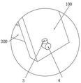
as shown in fig. 1 to 6, the connecting member of the light fabricated bracket includes a supporting connecting member 300 for supporting the transverse supporting beam 200 and the longitudinal connecting beam 100, and a first movable connecting member for connecting the longitudinal connecting beam 100 and the transverse supporting beam 200, wherein two ends of the supporting connecting member 300 are respectively connected to the transverse supporting beam 200 and the longitudinal connecting beam 100 through a second movable connecting member and a third movable connecting member, and the first movable connecting member, the second movable connecting member and the third movable connecting member respectively include a first elastic pin 1 and a first conical expansion pin 2, a second conical expansion pin 3 and a second elastic pin 4, a third conical expansion pin 5 and a third elastic pin 6.
In this embodiment, the first elastic pin 1 is connected with the longitudinal connecting beam 100 and the transverse supporting beam 200 in a matching manner through a pin hole, the second elastic pin 4 is connected with the longitudinal connecting beam 100 and the supporting connecting member 300 in a matching manner through a pin hole, and the third elastic pin 6 is connected with the transverse supporting beam 200 and the supporting connecting member 300 in a matching manner through a pin hole.
This device, through with vertical tie-beam 100, transverse supporting beam 200, the junction of supporting connecting piece 300 adopts elasticity pin 1 respectively, elasticity pin two 4 is connected with elasticity pin three 6, on the one hand, it passes through the cooperation of pinhole, can realize quick dismantlement and installation, the convenience of use with the transportation has been improved, on the other hand, because elasticity pin 1, elasticity pin two 4 possesses certain elasticity with elasticity pin three 6 itself, thereby can cushion the vibrations of tie point, thereby prevent the damage of off-premises station operation vibrations to the connecting piece, the security has been improved.
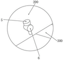
In this embodiment, the inner wall of the first elastic pin 1 is in inserted fit with a first conical expansion pin 2, the inner wall of the second elastic pin 4 is in inserted fit with a second conical expansion pin 3, and the inner wall of the third elastic pin 6 is in inserted fit with a third conical expansion pin 5; through setting up the toper and rise round pin 2, the toper rises round pin two 3 and the toper rises round pin three 5, it can be respectively to elastic pin 1, elastic pin two 4 with play axial limiting displacement, prevent that it from appearing droing, further increased the security.
In this embodiment: when the outdoor unit fixing device is used, the longitudinal connecting beam 100 is fixed on a wall surface, the transverse supporting beam 200 is fixed on the longitudinal connecting beam 100 through the elastic pin I1, the supporting connecting piece 300 is fixed on the longitudinal connecting beam 100 and the transverse supporting beam 200 through the elastic pin II 4 and the elastic pin III 6 respectively, and finally the conical expansion pin I2, the conical expansion pin II 3 and the conical expansion pin III 5 are inserted into the outdoor unit fixing device.
Example 2:
the connecting piece of light-duty assembled support, this embodiment make following improvement on the basis of embodiment 1, as shown in fig. 5, support connecting piece 300 includes through slide bar 8 sliding connection's articulated piece a7 and articulated piece B10, the outer wall of slide bar 8 has adjusting nut one 9 and adjusting nut two 12 through threaded connection, adjusting nut one 9 and articulated piece a7, adjusting nut two 12 and the relative one side outer wall of articulated piece B10 all overlap and are equipped with spring one 11.
In this embodiment: through improving the supporting connecting piece 300, the first hinge block A7, the first slide rod 8 and the first hinge block B10 are connected in a sliding mode, and the first spring 11 is additionally arranged on the outer wall of the first slide rod 8, so that the buffering shock resistance of the whole equipment can be improved, and the safety and the service life are improved.
Example 3:
the connecting member of the sobering assembled stent, according to the present embodiment, is modified from embodiment 1 in that, as shown in fig. 6, the supporting connecting member 300 includes a second hinge block a13 and a second hinge block B16, the outer walls of the second hinge block a13 and the second hinge block B16 are respectively welded with a second lead screw 19 and a first lead screw 17, and the second lead screw 19 and the first lead screw 17 are connected with the same strip nut 18 through threads with opposite rotation directions.
The outer walls of the first screw rod 17 and the second screw rod 19 are respectively connected with a second locknut 15 and a first locknut 14 through threads.
In this embodiment: through the improvement of the supporting and connecting piece 300, when the strip nut 18 is screwed, the distance between the first screw rod 17 and the second screw rod 19 can be changed, so that the length of the whole supporting and connecting piece 300 is changed, and the angle between the longitudinal connecting beam 100 and the transverse supporting beam 200 is changed, so that the horizontal arrangement of the outdoor unit can be kept even if the device is fixed on an uneven wall surface, and the use flexibility is improved.
The above description is only for the specific embodiments of the present invention, but the scope of the present invention is not limited thereto, and any person skilled in the art can easily think of various changes or substitutions within the technical scope of the present invention, which should be covered by the scope of the present invention. Therefore, the protection scope of the present invention shall be subject to the protection scope of the claims.
Claims (8)
1. Connecting piece of light-duty assembled support, including support connecting piece (300) that is used for supporting horizontal supporting beam (200) and vertical tie-beam (100), be used for connecting vertical tie-beam (100) and horizontal supporting beam (200) the swing joint spare one, its characterized in that: the two ends of the supporting connecting piece (300) are respectively connected to the transverse supporting beam (200) and the longitudinal connecting beam (100) through a movable connecting piece II and a movable connecting piece III, and the movable connecting piece I, the movable connecting piece II and the movable connecting piece III respectively comprise an elastic pin I (1), a conical expansion pin I (2), a conical expansion pin II (3), an elastic pin II (4), a conical expansion pin III (5) and an elastic pin III (6).
2. The connector of a light fabricated bracket as set forth in claim 1, wherein: the elastic pin I (1) is connected with the longitudinal connecting beam (100) and the transverse supporting beam (200) in a matched mode through a pin hole, the elastic pin II (4) is connected with the longitudinal connecting beam (100) and the supporting connecting piece (300) in a matched mode through a pin hole, and the elastic pin III (6) is connected with the transverse supporting beam (200) and the supporting connecting piece (300) in a matched mode through a pin hole.
3. The connector of a lightweight fabricated rack as set forth in claim 2, wherein: the inner wall of the elastic pin I (1) is in plug-in fit with a conical expansion pin I (2), the inner wall of the elastic pin II (4) is in plug-in fit with a conical expansion pin II (3), and the inner wall of the elastic pin III (6) is in plug-in fit with a conical expansion pin III (5).
4. The connector of a light fabricated bracket as set forth in claim 1, wherein: the supporting connecting piece (300) comprises a first hinged block A (7) and a first hinged block B (10) which are connected through a first sliding rod (8) in a sliding mode, and the outer wall of the first sliding rod (8) is connected with a first adjusting nut (9) and a second adjusting nut (12) through threads.
5. The connector of a light fabricated bracket as set forth in claim 4, wherein: and the outer walls of the opposite sides of the first adjusting nut (9) and the first hinge block A (7), the second adjusting nut (12) and the first hinge block B (10) are all sleeved with a first spring (11).
6. The connector of a light fabricated bracket as set forth in claim 1, wherein: the supporting connecting piece (300) comprises a second hinged block A (13) and a second hinged block B (16), and the outer walls of the second hinged block A (13) and the second hinged block B (16) are respectively and fixedly provided with a second screw rod (19) and a first screw rod (17).
7. The connector of a light fabricated bracket as set forth in claim 6, wherein: the second screw rod (19) and the first screw rod (17) are connected with the same long nut (18) through threads with opposite rotating directions.
8. The connector of a light fabricated bracket as set forth in claim 7, wherein: the outer walls of the first screw rod (17) and the second screw rod (19) are respectively connected with a second locknut (15) and a first locknut (14) through threads.
Priority Applications (1)
| Application Number | Priority Date | Filing Date | Title |
|---|---|---|---|
| CN202220836837.XU CN217464692U (en) | 2022-04-12 | 2022-04-12 | Connecting piece of light-duty assembled support |
Applications Claiming Priority (1)
| Application Number | Priority Date | Filing Date | Title |
|---|---|---|---|
| CN202220836837.XU CN217464692U (en) | 2022-04-12 | 2022-04-12 | Connecting piece of light-duty assembled support |
Publications (1)
| Publication Number | Publication Date |
|---|---|
| CN217464692U true CN217464692U (en) | 2022-09-20 |
Family
ID=83268742
Family Applications (1)
| Application Number | Title | Priority Date | Filing Date |
|---|---|---|---|
| CN202220836837.XU Active CN217464692U (en) | 2022-04-12 | 2022-04-12 | Connecting piece of light-duty assembled support |
Country Status (1)
| Country | Link |
|---|---|
| CN (1) | CN217464692U (en) |
-
2022
- 2022-04-12 CN CN202220836837.XU patent/CN217464692U/en active Active
Similar Documents
| Publication | Publication Date | Title |
|---|---|---|
| RU2007128232A (en) | SUPPORT STRUCTURE OF A VEHICLE POWER UNIT | |
| CN108592242B (en) | Vibration reduction structure of compressor and air conditioner | |
| US4188502A (en) | Spacer-damper | |
| CN217464692U (en) | Connecting piece of light-duty assembled support | |
| CN207905107U (en) | A kind of steel damper and assembling-type metal energy-dissipation beam column node | |
| US6308971B1 (en) | Rigid axle mounting for a vehicle | |
| CN109296897B (en) | Electronic information display board with strong wind resistance | |
| CN211035116U (en) | Weighing structure of aerial work platform and aerial work platform | |
| CN109849609A (en) | Rubber suspension and vehicle | |
| CN215482251U (en) | Stay cable lever mass damping device | |
| CN211547307U (en) | Novel become roof beam slab formula rubber support that falls is prevented in rigidity shock attenuation | |
| CN210976182U (en) | Stable form protection strutting arrangement of partition plate | |
| CN212641174U (en) | Recessive shear hinge device and bridge | |
| US7188820B2 (en) | Vibration damping floor structure | |
| CN110725200A (en) | Improve gallows device of fishback bearing capacity | |
| CN207998943U (en) | Brace type friction damping device | |
| CN107956857B (en) | Gear box vibration damper | |
| CN213331415U (en) | Supporting structure, tower barrel and wind generating set | |
| CN210992726U (en) | Installation component of telescopic pipe and fire engine | |
| CN214116267U (en) | Telescopic device for preventing suspension bridge from shaking | |
| CN203404874U (en) | Air conditioner mounting bracket | |
| CN104228512B (en) | A kind of X-type distance rod, rear suspension assembly and vehicle | |
| CN216003055U (en) | Unmanned aerial vehicle with descending shock-absorbing function | |
| CN217419299U (en) | Combined telescopic device with intelligent monitor | |
| CN218343480U (en) | Hanging bracket |
Legal Events
| Date | Code | Title | Description |
|---|---|---|---|
| GR01 | Patent grant | ||
| GR01 | Patent grant | ||
| PE01 | Entry into force of the registration of the contract for pledge of patent right |
Denomination of utility model: Connection components for lightweight prefabricated brackets Granted publication date: 20220920 Pledgee: SHANGHAI RURAL COMMERCIAL BANK Co.,Ltd. Pledgor: Shanghai Lianyu Industrial Co.,Ltd. Registration number: Y2024310000128 |
|
| PE01 | Entry into force of the registration of the contract for pledge of patent right |