CN217462883U - Multi-condition lower anti-rotation sliding bearing - Google Patents
Multi-condition lower anti-rotation sliding bearing Download PDFInfo
- Publication number
- CN217462883U CN217462883U CN202220944983.4U CN202220944983U CN217462883U CN 217462883 U CN217462883 U CN 217462883U CN 202220944983 U CN202220944983 U CN 202220944983U CN 217462883 U CN217462883 U CN 217462883U
- Authority
- CN
- China
- Prior art keywords
- base
- movable mounting
- lid
- sliding bearing
- inner ring
- Prior art date
- Legal status (The legal status is an assumption and is not a legal conclusion. Google has not performed a legal analysis and makes no representation as to the accuracy of the status listed.)
- Active
Links
Images



Abstract
The utility model discloses a rotatory slide bearing is prevented under many conditions relates to slide bearing technical field, including connecting the base, the top demountable installation of connecting the base has the connection lid, and the inside movable mounting of connecting the lid has an oil feed device, and the inside movable mounting of connecting the lid has inside swivel becket, and inside swivel becket movable mounting has fastening bolt at the top of connecting the base, the both ends movable mounting of connecting the lid. Above-mentioned scheme, in the device course of operation, rotate through the inner ring of inside activity, make the ball roll at the surface of activity inner ring, the bed plate is fixed through fastening bolt simultaneously, through pressing down the pressure lever with lubricating oil, it is tensile to press down pressure lever decline reset spring, the scarf joint piece breaks away from the scarf joint groove, make lubricating oil get into the surface of ball, and finally fall into the bottom in lower spacing groove, it is convenient to add lubricating oil, prevent lubricating oil leakage simultaneously, avoid the dust to fall into the inside of slide bearing simultaneously, it is more obvious to lubricate the effect, and long service life.
Description
Technical Field
The utility model relates to a slide bearing technical field, more specifically say, the utility model relates to a rotatory slide bearing is prevented under many conditions.
Background
The sliding bearing is a bearing which works under sliding friction, the sliding bearing works stably, reliably and noiselessly, under the condition of liquid lubrication, the sliding surface is separated by lubricating oil and is not in direct contact with the lubricating oil, the friction loss and the surface abrasion can be greatly reduced, an oil film also has certain vibration absorption capacity, but the starting friction resistance is larger, the part of the shaft supported by the bearing is called a shaft neck, the part matched with the shaft neck is called a bearing bush, the antifriction material layer cast on the inner surface of the part to improve the friction property of the surface of the bearing bush is called a bearing bush, and the materials of the bearing bush and the bearing bush are collectively called sliding bearing materials.
The existing sliding bearing is used, because the outer ring of the sliding bearing is not fixed, in the using process, if the friction force is large, the outer ring can easily rotate along with the inner ring, the rotating efficiency is reduced, the service life of the sliding bearing is simultaneously reduced, meanwhile, the side edge of the sliding bearing is leaked outside, lubricating oil is added, the lubricating oil can easily drip, dust can be adhered, and the lubricating effect is reduced.
SUMMERY OF THE UTILITY MODEL
In order to overcome prior art's above-mentioned defect, the embodiment of the utility model provides a rotatory slide bearing is prevented under many conditions to solve current slide bearing at the in-process that uses, because slide bearing's outer loop does not fix, at the in-process that uses, if when frictional force is great, it is rotatory together along with the inner ring to make the outer loop very easily, reduce the rotation efficiency, reduce slide bearing's life simultaneously, slide bearing's side leaks outside simultaneously, it drips very easily to add lubricating oil, still can glue the dust, reduce the problem of lubricated effect.
In order to solve the technical problem, the utility model provides a following technical scheme: the utility model provides a rotatory slide bearing is prevented under many conditions, includes the connection base, the top demountable installation who connects the base has the connection lid, the inside movable mounting who connects the lid has the oil feed device, the inside movable mounting who connects the lid has inside swivel becket, inside swivel becket movable mounting is at the top of connecting the base, the both ends movable mounting who connects the lid has fastening bolt.
Preferably, the connection base includes the bed plate, fastening bolt movable mounting is at the both ends of bed plate, the top fixed mounting of bed plate has the outer loop base, connecting hole down has been seted up to the inside of outer loop base, spacing groove under has been seted up to the inside of connecting hole down, the bolt hole corresponding with fastening bolt has all been seted up at the both ends at outer loop base top.
Preferably, inside rotating ring is including the activity inner ring, the equal fixed mounting in both ends of activity inner ring has the stopper, the surface movable mounting of activity inner ring has the adapter sleeve, the inside movable mounting of adapter sleeve has the ball.
Preferably, the connecting cover comprises a cover body, an upper connecting hole is formed in the cover body, an upper limiting groove is formed in the upper connecting hole, an oil inlet hole is formed in the cover body, an embedding groove is formed in the bottom of the oil inlet hole, a connecting groove is formed in the bottom of the embedding groove, and the fastening bolts are movably mounted on two sides of the cover body respectively.
Preferably, the oil feed device is including pressing the depression bar, the bottom fixed mounting who presses the depression bar has the connecting block, the top fixed mounting of connecting block has the scarf joint piece, the top movable mounting of scarf joint piece has reset spring, reset spring movable mounting is in the bottom of scarf joint groove, press the inside of depression bar movable mounting at the inlet port.
The utility model discloses a technological effect and advantage:
in the scheme, the movable inner ring is movably arranged inside the lower connecting hole, the balls are movably arranged inside the lower limiting groove, the balls roll on the outer surface of the movable inner ring through the rotation of the inner movable inner ring in the working process of the device, the relative motion of the movable inner ring and the outer ring base is more flexible, and meanwhile, the base plate is fixed through the fastening bolt, so that the movable inner ring and the outer ring base move relatively when the sliding bearing moves under multiple conditions, the outer ring base is prevented from rotating together due to friction force, the service efficiency of the bearing is improved, and the service life of the sliding bearing is prolonged; lid demountable installation is at the top of outer loop base, and in the device course of operation, through pressing down the press rod with lubricating oil, it is tensile to press down the depression bar decline reset spring, and the scarf joint piece breaks away from the scarf joint groove, makes lubricating oil get into the surface of ball to finally fall into the bottom in lower spacing groove, it is convenient to add lubricating oil, prevents lubricating oil leakage simultaneously, avoids the dust to fall into the inside of slide bearing simultaneously, and lubricated effect is more obvious.
Drawings
Fig. 1 is a schematic view of the overall structure of the present invention;
FIG. 2 is a schematic view of the connection base structure of the present invention;
FIG. 3 is a schematic view of the inner rotating ring structure of the present invention;
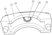
FIG. 4 is a schematic view of the connecting cover of the present invention;
fig. 5 is the utility model discloses an oil feed device schematic structure.
The reference signs are: 1. connecting a base; 2. a connecting cover; 3. an inner rotating ring; 4. an oil inlet device; 5. fastening a bolt; 11. a base plate; 12. an outer ring base; 13. a lower connection hole; 14. a lower limiting groove; 15. bolt holes; 21. a cover body; 22. an upper connecting hole; 23. an upper limiting groove; 24. an oil inlet hole; 25. embedding grooves; 26. connecting grooves; 31. a movable inner ring; 32. a limiting block; 33. connecting sleeves; 34. a ball bearing; 41. a pressing lever; 42. connecting blocks; 43. a scarf block; 44. a return spring.
Detailed Description
In order to make the technical problems, technical solutions and advantages to be solved by the present invention clearer, the following detailed description will be given with reference to the accompanying drawings and specific embodiments.
Like fig. 1 to fig. 5, the embodiment of the utility model provides a rotatory slide bearing is prevented under many conditions, including connecting base 1, the top demountable installation of connecting base 1 has connection lid 2, and the inside movable mounting of connecting lid 2 has oil feed device 4, and the inside movable mounting of connecting lid 2 has inside swivel ring 3, and inside swivel ring 3 movable mounting has fastening bolt 5 at the top of connecting base 1, the both ends movable mounting of connecting lid 2.
As shown in fig. 2 and fig. 3, the connecting base 1 includes a base plate 11, fastening bolts 5 are movably mounted at two ends of the base plate 11, an outer ring base 12 is fixedly mounted at the top of the base plate 11, a lower connecting hole 13 is formed inside the outer ring base 12, a lower limiting groove 14 is formed inside the lower connecting hole 13, and bolt holes 15 corresponding to the fastening bolts 5 are formed at two ends of the top of the outer ring base 12; the inner rotating ring 3 comprises a movable inner ring 31, two ends of the movable inner ring 31 are fixedly provided with limiting blocks 32, the outer surface of the movable inner ring 31 is movably provided with a connecting sleeve 33, and balls 34 are movably arranged in the connecting sleeve 33.
Specifically, activity inner ring 31 movable mounting is in the inside of connecting hole 13 down, ball 34 movable mounting is in the inside of spacing groove 14 down, in the device course of operation, rotate through inside activity inner ring 31, make ball 34 roll at the surface of activity inner ring 31, activity inner ring 31 is more nimble with outer loop base 12 relative motion, bedplate 11 fixes through fastening bolt 5 simultaneously, when making slide bearing move under many pieces, activity inner ring 31 and outer loop base 12 relative motion, prevent outer loop base 12 because frictional force rotary motion together, the availability factor of bearing is improved, the life of slide bearing has been prolonged simultaneously.
As shown in fig. 4 and 5, the connection cover 2 includes a cover body 21, an upper connection hole 22 is formed in the cover body 21, an upper limit groove 23 is formed in the upper connection hole 22, an oil inlet hole 24 is formed in the cover body 21, an embedding groove 25 is formed at the part of the oil inlet hole 24, a connection groove 26 is formed at the bottom of the embedding groove 25, and the fastening bolts 5 are respectively movably mounted on two sides of the cover body 21; the oil inlet device 4 comprises a pressing rod 41, a connecting block 42 is fixedly installed at the bottom of the pressing rod 41, an embedding block 43 is fixedly installed at the top of the connecting block 42, a return spring 44 is movably installed at the top of the embedding block 43, the return spring 44 is movably installed at the bottom of the embedding groove 25, and the pressing rod 41 is movably installed inside the oil inlet hole 24.
Specifically, lid 21 demountable installation is at the top of outer loop base 12, and in the device course of operation, through pressing down press bar 41 with lubricating oil, press bar 41 decline reset spring 44 tensile, and scarf joint piece 43 breaks away from scarf joint groove 25, makes lubricating oil get into the surface of ball 34 to finally fall into the bottom of lower spacing groove 14, it is convenient to add lubricating oil, prevents simultaneously that lubricating oil from leaking, avoids the dust to fall into the inside of slide bearing simultaneously, and lubricated effect is more obvious.
The working process of the utility model is as follows:
the movable inner ring 31 is movably arranged in the lower connecting hole 13, the balls 34 are movably arranged in the lower limiting groove 14, in the working process of the device, the balls 34 roll on the outer surface of the movable inner ring 31 through the rotation of the inner movable inner ring 31, the relative motion of the movable inner ring 31 and the outer ring base 12 is more flexible, meanwhile, the base plate 11 is fixed through the fastening bolt 5, when the sliding bearing moves under multiple conditions, the movable inner ring 31 and the outer ring base 12 move relatively, the outer ring base 12 is prevented from rotating together due to friction, the service efficiency of the bearing is improved, and the service life of the sliding bearing is prolonged;
The points to be finally explained are: first, in the description of the present application, it should be noted that, unless otherwise specified and limited, the terms "mounted," "connected," and "connected" should be understood broadly, and may be a mechanical connection or an electrical connection, or a communication between two elements, and may be a direct connection, and "upper," "lower," "left," and "right" are only used to indicate a relative positional relationship, and when the absolute position of the object to be described is changed, the relative positional relationship may be changed;
secondly, the method comprises the following steps: in the drawings of the disclosed embodiments of the present invention, only the structures related to the disclosed embodiments are referred to, and other structures can refer to the common design, and under the condition of no conflict, the same embodiment and different embodiments of the present invention can be combined with each other;
and finally: the above description is only for the preferred embodiment of the present invention and should not be taken as limiting the invention, and any modifications, equivalent replacements, improvements, etc. made within the spirit and principle of the present invention should be included in the protection scope of the present invention.
Claims (5)
1. The utility model provides a rotation-proof sliding bearing under many conditions, is including connecting base (1), its characterized in that, the top demountable installation of connecting base (1) has connection lid (2), the inside movable mounting of connecting lid (2) has oil feed device (4), the inside movable mounting of connecting lid (2) has inside swivel ring (3), inside swivel ring (3) movable mounting is at the top of connecting base (1), the both ends movable mounting of connecting lid (2) has fastening bolt (5).
2. The multi-condition lower anti-rotation sliding bearing according to claim 1, wherein the connecting base (1) comprises a base plate (11), the fastening bolts (5) are movably mounted at two ends of the base plate (11), an outer ring base (12) is fixedly mounted at the top of the base plate (11), a lower connecting hole (13) is formed in the outer ring base (12), a lower limiting groove (14) is formed in the lower connecting hole (13), and bolt holes (15) corresponding to the fastening bolts (5) are formed at two ends of the top of the outer ring base (12).
3. The multi-condition anti-rotation sliding bearing according to claim 1, wherein the inner rotating ring (3) comprises a movable inner ring (31), two ends of the movable inner ring (31) are both fixedly provided with a limiting block (32), the outer surface of the movable inner ring (31) is movably provided with a connecting sleeve (33), and the inner part of the connecting sleeve (33) is movably provided with a ball (34).
4. The multi-condition lower anti-rotation sliding bearing according to claim 1, wherein the connection cover (2) comprises a cover body (21), an upper connection hole (22) is formed in the cover body (21), an upper limit groove (23) is formed in the upper connection hole (22), an oil inlet (24) is formed in the cover body (21), an embedding groove (25) is formed in the bottom of the oil inlet (24), a connection groove (26) is formed in the bottom of the embedding groove (25), and the fastening bolts (5) are movably mounted on two sides of the cover body (21) respectively.
5. The multi-condition anti-rotation sliding bearing according to claim 1, wherein the oil feeding device (4) comprises a pressing rod (41), a connecting block (42) is fixedly mounted at the bottom of the pressing rod (41), an embedding block (43) is fixedly mounted at the top of the connecting block (42), a return spring (44) is movably mounted at the top of the embedding block (43), the return spring (44) is movably mounted at the bottom of the embedding groove (25), and the pressing rod (41) is movably mounted inside the oil inlet hole (24).
Priority Applications (1)
| Application Number | Priority Date | Filing Date | Title |
|---|---|---|---|
| CN202220944983.4U CN217462883U (en) | 2022-04-22 | 2022-04-22 | Multi-condition lower anti-rotation sliding bearing |
Applications Claiming Priority (1)
| Application Number | Priority Date | Filing Date | Title |
|---|---|---|---|
| CN202220944983.4U CN217462883U (en) | 2022-04-22 | 2022-04-22 | Multi-condition lower anti-rotation sliding bearing |
Publications (1)
| Publication Number | Publication Date |
|---|---|
| CN217462883U true CN217462883U (en) | 2022-09-20 |
Family
ID=83269098
Family Applications (1)
| Application Number | Title | Priority Date | Filing Date |
|---|---|---|---|
| CN202220944983.4U Active CN217462883U (en) | 2022-04-22 | 2022-04-22 | Multi-condition lower anti-rotation sliding bearing |
Country Status (1)
| Country | Link |
|---|---|
| CN (1) | CN217462883U (en) |
-
2022
- 2022-04-22 CN CN202220944983.4U patent/CN217462883U/en active Active
Similar Documents
| Publication | Publication Date | Title |
|---|---|---|
| KR20060051280A (en) | Rotary union for directing a heat exchange fluid | |
| EP0972960B1 (en) | Linear motion guide unit with lubricating plate assembly | |
| JP2010520411A (en) | Seal cartridge for vacuum pump | |
| CN111894993A (en) | Bearing mounting structure | |
| JPH10205534A (en) | Direct-acting guide unit with lubrication plate | |
| CN217462883U (en) | Multi-condition lower anti-rotation sliding bearing | |
| CN101498327A (en) | Oil film supporting servo hydraulic cylinder | |
| US5947496A (en) | Low lash idler arm assembly | |
| CN201382087Y (en) | Mill sliding shoe bearing bush aligning device | |
| CN202545568U (en) | Sealed full cylindrical roller bearing | |
| CN114017443A (en) | Miniature ball bush direction subassembly | |
| CN203009586U (en) | Self-lubricating bearing for automotive brake | |
| CN203082040U (en) | Trunnion bearing block of converter transmission side | |
| CN113757261A (en) | Multi-piece type long-axis tile dynamic pressure oil film bearing | |
| CN101799043A (en) | Thrust articulated bearing for large steel ladle rotary table | |
| CN112303130A (en) | Adjustable damping roll bearing seat | |
| CN201158163Y (en) | Static pressure guide post for press | |
| CN217055992U (en) | Slide bearing with prevention of seepage water anti-overflow fat function | |
| CN201363281Y (en) | Water guide bearing structure for horizontal or diagonal flow pump | |
| CN213511729U (en) | Stamping bearing seat with good sealing performance | |
| CN206608471U (en) | A kind of pair of drive system regulating center bearing base unit | |
| CN201109196Y (en) | Press static guide pillar | |
| CN216009271U (en) | Bearing convenient to lubricate | |
| CN218266810U (en) | Radial spherical plain bearing | |
| CN201636211U (en) | Automobile universal joint self-lubricating bearing |
Legal Events
| Date | Code | Title | Description |
|---|---|---|---|
| GR01 | Patent grant | ||
| GR01 | Patent grant |