CN217444865U - Energy-saving high-low voltage reactive power compensation cabinet - Google Patents
Energy-saving high-low voltage reactive power compensation cabinet Download PDFInfo
- Publication number
- CN217444865U CN217444865U CN202221061953.5U CN202221061953U CN217444865U CN 217444865 U CN217444865 U CN 217444865U CN 202221061953 U CN202221061953 U CN 202221061953U CN 217444865 U CN217444865 U CN 217444865U
- Authority
- CN
- China
- Prior art keywords
- installation
- fan
- install bin
- reactive power
- mounting
- Prior art date
- Legal status (The legal status is an assumption and is not a legal conclusion. Google has not performed a legal analysis and makes no representation as to the accuracy of the status listed.)
- Active
Links
Images


Abstract
The utility model relates to a compensation cabinet technical field especially relates to an energy-saving high-low pressure reactive power compensation cabinet. The technical scheme comprises the following steps: the protective box comprises a protective box body, an installation box and a connecting wire, wherein an installation chamber and a heat dissipation chamber are respectively arranged inside the protective box body, a protective cover corresponding to the installation chamber is movably installed at the front end of the protective box body, an installation cover corresponding to the heat dissipation chamber is movably installed at the front end of the protective box body, the installation box is slidably installed inside the heat dissipation chamber, a grid plate corresponding to the installation box is fixedly installed inside the installation box, and a fan is movably installed inside the installation box through a movable rod. The utility model discloses a be provided with mutually supporting between fan, movable rod, grid plate and the install bin, through the fan can be convenient carry out reciprocating motion in the inside of install bin, can evenly dispel the heat at the condenser to install the indoor through the fan, can effectual improvement radiating effect, increased the practicality, improved life.
Description
Technical Field
The utility model relates to a compensation cabinet technical field specifically is an energy-saving high-low pressure reactive power compensation cabinet.
Background
The load type in the power system mostly belongs to inductive load, and power electronic equipment is widely used by power utilization enterprises, so that the power factor of a power grid is lower, the lower power factor reduces the equipment utilization rate, the power supply investment is increased, the voltage quality is damaged, the service life of the equipment is reduced, the line loss is greatly increased, the inductive load can be balanced and the power factor is improved by connecting a capacitance compensation cabinet in the power system, so that the utilization rate of the equipment is improved, and therefore, an energy-saving high-low voltage reactive compensation cabinet is required to be used.
Through search, the patent publication No. CN211266486U discloses an energy-saving high-low voltage reactive power compensation cabinet convenient for heat dissipation, the utility model provides an energy-saving high-low voltage reactive power compensation cabinet convenient for heat dissipation, which comprises a high-low voltage reactive power compensation cabinet body, one side of the high-low voltage reactive power compensation cabinet body is hinged with a cabinet door through a hinge, a base is arranged below the high-low voltage reactive power compensation cabinet body, a wiring terminal is fixedly arranged above the high-low voltage reactive power compensation cabinet body, a vertical fixing frame is fixedly arranged in the high-low voltage reactive power compensation cabinet body through bolts, a circuit breaker is fixedly arranged above the vertical fixing frame through a bolt, a capacitor bracket is fixedly arranged below the vertical fixing frame through a bolt, the capacitor support is provided with a plurality of capacitor mounting grooves, capacitors are mounted in the capacitor mounting grooves, and a heat dissipation structure is mounted below the capacitor support.
The existing energy-saving high-low voltage reactive power compensation cabinet has the following defects:
1. in the using process of the existing energy-saving high-low voltage reactive power compensation cabinet, because the internal capacitor of the compensation cabinet is easy to heat during use, the capacitor is easy to burn out due to serious heating, and the existing heat dissipation effect cannot uniformly dissipate heat of the capacitor, the heat dissipation performance is poor, the normal use of the compensation cabinet is influenced, and the service life is shortened;
2. general energy-saving high-low voltage reactive power compensator cabinet lacks bunch structure, and the internal connection line of compensation cabinet in the in-process compensation cabinet that uses is more, and the in-process connecting wire that keeps in repair is in a jumble inconvenient arranges in order, influences staff's convenience, has reduced the practicality, for this we provide an energy-saving high-low voltage reactive power compensator cabinet and solve current problem.
SUMMERY OF THE UTILITY MODEL
The utility model aims at providing an energy-saving high-low pressure reactive power compensator cabinet to solve the problem of proposing among the above-mentioned background art.
In order to achieve the above object, the utility model provides a following technical scheme: the utility model provides an energy-saving high-low voltage reactive power compensator cabinet, includes protecting box, install bin and connecting wire, the inside of protecting box is provided with installation room and heat dissipation room respectively, the front end movable mounting of protecting box has the protective cover that corresponds with the installation room, the front end movable mounting of protecting box has the installation lid that corresponds with the heat dissipation room, the inside slidable mounting of heat dissipation room has the install bin, the inside fixed mounting of install bin has the grid plate that corresponds with the install bin, there is the fan inside of install bin through movable rod movable mounting, movable mounting has the lead screw between fan and the install bin, the inside fixed mounting of install bin has the connecting wire, the inside fixed mounting of install bin has with connecting wire complex fixed plate, the front end slidable mounting of fixed plate has with connecting wire complex grip block.
The lead screw is driven to rotate synchronously through the rotation of the servo motor, the fan can be moved conveniently in the installation box, and the capacitor in the installation chamber can be uniformly cooled through the fan, so that the heat dissipation performance is better, the practicability is improved, and the service life is prolonged.
Preferably, the front end of protective cover is provided with the observation window, and it is fixed through fixed knob between heat dissipation room and the install bin. Through the fixed knob can be convenient fix the install bin in the inside of heat dissipation room, make the in-process of installing and dismantling more convenient, increased the practicality, convenient operation is swift.
Preferably, the front end of the mounting cover is fixedly provided with a handle, and the front end of the mounting cover at the bottom of the handle is provided with a vent. The ventilation opening can conveniently supply air to the inside of the installation box, so that the inside is more efficient in heat dissipation.
Preferably, the fan and the movable rod are movably mounted through a movable sleeve, and a protective net is fixedly mounted at the top of the fan. Through the movable sleeve can be convenient remove the fan along the movable rod, make the fan can be convenient carry out reciprocating motion, carry out radiating in-process more high-efficient to installation indoor portion, increased the practicality.
Preferably, the bottom of the installation box is fixedly provided with a servo motor, and the output end of the servo motor and the screw rod are installed through a bevel gear set in a transmission mode. The fan can be conveniently moved along the inside of the installation box through the lead screw, and the capacitor of the installation chamber can be conveniently and uniformly cooled through the reciprocating movement of the fan.
Preferably, the mounting chamber and the clamping plate are slidably mounted through a sliding groove, the clamping plate and the fixing plate are spirally mounted through a threaded rod, and a turntable is fixedly mounted at the front end of the threaded rod. Draw close each other between grip block and the fixed plate, make the grip block can remove along the inside of sliding tray, through mutually supporting between grip block and the fixed plate, carry out spacing classification with the connecting wire, it is more convenient at the in-process that uses.
Compared with the prior art, the beneficial effects of the utility model are that:
1. through being provided with mutually supporting between fan, movable rod, the grid plate and the install bin, can be convenient through the fan carry out reciprocating motion in the inside of install bin, can evenly dispel the heat at the condenser to the install bin through the fan, can effectual improvement radiating effect, increased the practicality, improved life.
2. Through being provided with the fixed plate, mutually supporting between grip block and the carousel, can be convenient through rotatory carousel draw close each other between grip block and the fixed plate, make the grip block can remove along the inside of sliding tray, through mutually supporting between grip block and the fixed plate, carry out spacing classification with the connecting wire, it is more convenient at the in-process that uses, improved the convenience when maintaining, increased the practicality.
Drawings
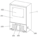
Fig. 1 is a first external perspective front view of the present invention;
fig. 2 is a second perspective front view of the present invention;
FIG. 3 is a partial structural view of the fan of the present invention;
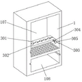
fig. 4 is a schematic view of a local structure of the fixing plate of the present invention.
In the figure: 1. a protective box; 101. a protective cover; 102. an observation window; 103. installing a cover; 104. a grip; 105. a vent; 106. fixing the knob; 107. an installation chamber; 108. a heat dissipation chamber; 2. installing a box; 201. a grid plate; 202. a movable rod; 203. a movable sleeve; 204. a fan; 205. a protective net; 206. a screw rod; 207. a bevel gear set; 208. a servo motor; 3. a connecting wire; 301. a fixing plate; 302. a clamping plate; 303. a sliding groove; 304. a threaded rod; 305. a turntable.
Detailed Description
The technical solution of the present invention will be further explained with reference to the accompanying drawings and specific embodiments.
Example one
As shown in fig. 1-4, the energy-saving high-low voltage reactive power compensation cabinet provided by the present invention comprises a protection box 1, an installation box 2 and a connection line 3, wherein the interior of the protection box 1 is respectively provided with an installation chamber 107 and a heat dissipation chamber 108, the front end of the protection box 1 is movably installed with a protection cover 101 corresponding to the installation chamber 107, the front end of the protection box 1 is movably installed with an installation cover 103 corresponding to the heat dissipation chamber 108, the interior of the heat dissipation chamber 108 is slidably installed with the installation box 2, the interior of the installation chamber 107 is fixedly installed with a grid plate 201 corresponding to the installation box 2, the interior of the installation box 2 is movably installed with a fan 204 through a movable rod 202, a lead screw 206 is movably installed between the fan 204 and the installation box 2, the interior of the installation chamber 107 is fixedly installed with the connection line 3, the interior of the installation chamber 107 is fixedly installed with a fixing plate 301 matched with the connection line 3, the front end of the fixing plate 301 is slidably installed with a clamping plate 302 matched with the connection line 3, the front end of the protective cover 101 is provided with an observation window 102, the front end of the mounting cover 103 is fixedly provided with a handle 104, the front end of the mounting cover 103 at the bottom of the handle 104 is provided with a vent 105, the top of the fan 204 is fixedly provided with a protective net 205, the bottom of the mounting box 2 is fixedly provided with a servo motor 208, the output end of the servo motor 208 and the screw rod 206 are in transmission mounting through a bevel gear set 207, the mounting chamber 107 and the clamping plate 302 are in sliding mounting through a sliding groove 303, the clamping plate 302 and the fixing plate 301 are in spiral mounting through a threaded rod 304, and the front end of the threaded rod 304 is fixedly provided with a rotary table 305.
The working principle of the energy-saving high-low voltage reactive power compensation cabinet based on the embodiment 1 is as follows: the rotatory synchronous drive lead screw 206 through servo motor 208 is rotatory, make fan 204 that can be convenient through lead screw 206 remove along the inside of install bin 2, can be convenient carry out even heat dissipation to the condenser of installation room 107 through fan 204 reciprocating motion, make heat dispersion better, the practicality has been increased, service life has been improved, through rotatory carousel 305, it is rotatory to drive threaded rod 304 in step through rotating carousel 305, can be convenient draw close each other between grip block 302 and the fixed plate 301, make grip block 302 can remove along the inside of sliding tray 303, through mutually supporting between grip block 302 and the fixed plate 301, carry out spacing classification with connecting wire 3, it is more convenient at the in-process of using, and convenient and fast operation, the practicality has been increased.
Example two
As shown in fig. 1-4, the utility model provides an energy-saving high-low voltage reactive power compensator cabinet compares in embodiment one, and this embodiment still includes: the fan 204 and the movable rod 202 are movably mounted through a movable sleeve 203, and the heat dissipation chamber 108 and the mounting box 2 are fixed through a fixing knob 106.
In this embodiment, can be convenient through movable sleeve 203 remove fan 204 along movable rod 202, make fan 204 can be convenient carry out reciprocating motion, carry out radiating in-process more high-efficient to installation room 107 inside, increased the practicality, can be convenient fix install bin 2 in the inside of heat dissipation room 108 through fixed knob 106, make installation and dismantlement in-process more convenient, increased the practicality, convenient operation is swift.
The above embodiments are merely some preferred embodiments of the present invention, and those skilled in the art can make various alternative modifications and combinations to the above embodiments based on the technical solution of the present invention and the related teachings of the above embodiments.
Claims (6)
1. The utility model provides an energy-saving high-low voltage reactive power compensator cabinet, includes protecting box (1), install bin (2) and connecting wire (3), its characterized in that: the utility model discloses a protective box for the solar water heater, including protective box (1), protection box (1) inside is provided with installation room (107) and heat dissipation room (108) respectively, the front end movable mounting of protective box (1) has protective cover (101) that corresponds with installation room (107), the front end movable mounting of protective box (1) has installation lid (103) that correspond with heat dissipation room (108), the inside slidable mounting of heat dissipation room (108) has install bin (2), the inside fixed mounting of installation room (107) has grid plate (201) that corresponds with install bin (2), the inside of install bin (2) has fan (204) through movable rod (202) movable mounting, movable mounting has lead screw (206) between fan (204) and install bin (2), the inside fixed mounting of install bin (107) has connecting wire (3), the inside fixed mounting of install bin (107) has fixed plate (301) with connecting wire (3) complex, the front end of the fixing plate (301) is provided with a clamping plate (302) matched with the connecting wire (3) in a sliding way.
2. The energy-saving high-low voltage reactive power compensation cabinet according to claim 1, wherein: an observation window (102) is arranged at the front end of the protective cover (101), and the heat dissipation chamber (108) and the installation box (2) are fixed through a fixing knob (106).
3. The energy-saving high-low voltage reactive power compensation cabinet according to claim 1, wherein: the front end of the mounting cover (103) is fixedly provided with a grip (104), and the front end of the mounting cover (103) at the bottom of the grip (104) is provided with a ventilation opening (105).
4. The energy-saving high-low voltage reactive power compensation cabinet according to claim 1, wherein: the fan (204) and the movable rod (202) are movably arranged through a movable sleeve (203), and a protective net (205) is fixedly arranged at the top of the fan (204).
5. The energy-saving high-low voltage reactive power compensation cabinet according to claim 1, wherein: the bottom fixed mounting of install bin (2) has servo motor (208), and installs through bevel gear set (207) transmission between the output of servo motor (208) and lead screw (206).
6. The energy-saving high-low voltage reactive power compensation cabinet according to claim 1, wherein: the mounting chamber (107) and the clamping plate (302) are slidably mounted through a sliding groove (303), the clamping plate (302) and the fixing plate (301) are spirally mounted through a threaded rod (304), and a rotary disc (305) is fixedly mounted at the front end of the threaded rod (304).
Priority Applications (1)
| Application Number | Priority Date | Filing Date | Title |
|---|---|---|---|
| CN202221061953.5U CN217444865U (en) | 2022-05-06 | 2022-05-06 | Energy-saving high-low voltage reactive power compensation cabinet |
Applications Claiming Priority (1)
| Application Number | Priority Date | Filing Date | Title |
|---|---|---|---|
| CN202221061953.5U CN217444865U (en) | 2022-05-06 | 2022-05-06 | Energy-saving high-low voltage reactive power compensation cabinet |
Publications (1)
| Publication Number | Publication Date |
|---|---|
| CN217444865U true CN217444865U (en) | 2022-09-16 |
Family
ID=83220314
Family Applications (1)
| Application Number | Title | Priority Date | Filing Date |
|---|---|---|---|
| CN202221061953.5U Active CN217444865U (en) | 2022-05-06 | 2022-05-06 | Energy-saving high-low voltage reactive power compensation cabinet |
Country Status (1)
| Country | Link |
|---|---|
| CN (1) | CN217444865U (en) |
-
2022
- 2022-05-06 CN CN202221061953.5U patent/CN217444865U/en active Active
Similar Documents
| Publication | Publication Date | Title |
|---|---|---|
| CN217444865U (en) | Energy-saving high-low voltage reactive power compensation cabinet | |
| CN215222132U (en) | Photovoltaic power generation inverter cabinet | |
| CN211930010U (en) | Electric power home-entry plug-in type power supply equipment | |
| CN219535815U (en) | Heat radiation structure for motor | |
| CN219086558U (en) | Switch board convenient to installation | |
| CN220341312U (en) | Battery cabinet bottom air supply mechanism | |
| CN220358586U (en) | Dampproofing electric capacity compensation cabinet dispels heat | |
| CN220421689U (en) | Photovoltaic power station with energy storage equipment | |
| CN213462781U (en) | Static var generator with good protection performance and convenient maintenance | |
| CN219697342U (en) | Installation fixing device for UPS power supply | |
| CN220732110U (en) | UPS power supply equipment convenient to maintain | |
| CN213638520U (en) | Automatic control equipment box with wire harness storage structure | |
| CN220172689U (en) | Switch cabinet for electrical engineering | |
| CN218770667U (en) | High stability GGD series low-voltage board | |
| CN220291889U (en) | High-voltage reactance soft start cabinet convenient for installation of internal devices | |
| CN213257537U (en) | Environment-friendly gear hobbing machine is used in clutch processing | |
| CN220421149U (en) | Electric control cabinet with lighting function | |
| CN216489101U (en) | Automatic dust collector of low pressure reactive compensation cabinet | |
| CN216312467U (en) | Box-type substation with efficient heat dissipation | |
| CN219717610U (en) | Wall-mounted direct current screen | |
| CN220754156U (en) | Low-voltage unpowered compensation device with good heat dissipation effect | |
| CN220233925U (en) | Power distribution cabinet heat abstractor | |
| CN220527942U (en) | Environment-friendly photovoltaic energy storage device | |
| CN219371755U (en) | Protection assembly for electrical control cabinet | |
| CN220379324U (en) | Equipment management system operation terminal |
Legal Events
| Date | Code | Title | Description |
|---|---|---|---|
| GR01 | Patent grant | ||
| GR01 | Patent grant |