CN217412776U - Welding cutting device based on hoisting and transporting equipment - Google Patents
Welding cutting device based on hoisting and transporting equipment Download PDFInfo
- Publication number
- CN217412776U CN217412776U CN202221269213.0U CN202221269213U CN217412776U CN 217412776 U CN217412776 U CN 217412776U CN 202221269213 U CN202221269213 U CN 202221269213U CN 217412776 U CN217412776 U CN 217412776U
- Authority
- CN
- China
- Prior art keywords
- frame
- cutting device
- welding
- threaded
- hoisting
- Prior art date
- Legal status (The legal status is an assumption and is not a legal conclusion. Google has not performed a legal analysis and makes no representation as to the accuracy of the status listed.)
- Active
Links
Images


Abstract
The utility model discloses a welding cutting device based on jack-up transportation equipment, including control box and frame, the control box is installed on the top of frame, install the drive case on the outer wall of control box, the frame internally mounted of drive case below has the support frame, four group's holding framves are installed on the top of support frame, the inside of holding frame all is equipped with the driving arm, the briquetting is all installed to the bottom of driving arm, the holding frame top of driving arm one side all is equipped with the thread bush, the inside of thread bush all is equipped with the threaded rod, and the bottom and the driving arm swing joint of threaded rod, the handle is all installed on the top of threaded rod. The utility model discloses not only realized that welding cutting device is fixed to the quick centre gripping of jack-up transportation equipment steel sheet for welding cutting device's clamping speed has improved welding cutting device's work efficiency moreover.
Description
Technical Field
The utility model relates to a welding cutting device technical field specifically is a welding cutting device based on jack-up transportation equipment.
Background
The plasma cutting machine can be matched with different working gases to cut various metals which are difficult to cut by oxygen, particularly stainless steel, carbon steel, aluminum, copper and the like, has better cutting effect, and has the main advantages that when the metals with small thickness are cut, the plasma cutting speed is high, the cutting surface is bright and clean, the thermal deformation is small, and a heat affected zone is hardly generated, so that the welding cutting device has important application in the field of steel plate processing of hoisting and transporting equipment.
This type of welding cutting device on the market is various today, can satisfy people's user demand basically, but still has certain problem, and the quick centre gripping of jack-up transportation equipment steel sheet is fixed not convenient for generally when using to this type of welding cutting device that has now, and great influence has brought very big influence to the clamping efficiency of work piece when welding cutting device uses the clamping speed of work piece.
SUMMERY OF THE UTILITY MODEL
An object of the utility model is to provide a welding cutting device based on jack-up transportation equipment to it is not convenient for the fixed problem of the quick centre gripping of jack-up transportation equipment steel sheet to provide welding cutting device in solving above-mentioned background art.
In order to achieve the above object, the utility model provides a following technical scheme: the utility model provides a welding cutting device based on jack-up transportation equipment, includes control box and frame, the control box is installed on the top of frame, install the drive case on the outer wall of control box, the frame internally mounted of drive case below has the support frame, four group's holding framves are installed on the top of support frame, the inside of holding frame all is equipped with the driving arm, the briquetting is all installed to the bottom of driving arm, the holding frame top of driving arm one side all is equipped with the thread bush, the inside of thread bush all is equipped with the threaded rod, and the bottom and the driving arm swing joint of threaded rod, the handle is all installed on the top of threaded rod.
Preferably, a lengthened screw rod is installed inside the rack below the support frame, and a screw rod sleeve is sleeved on the surface of the lengthened screw rod.
Preferably, the transmission frame is installed on the top of lead screw cover, and the top of transmission frame is connected with the support frame.
Preferably, a first rotary driving part is installed inside the rack on one side of the screw rod sleeve, and the output end of the first rotary driving part is connected with the lengthened screw rod.
Preferably, a threaded transmission rod is arranged inside the driving box, a threaded frame is arranged on the outer wall of the threaded transmission rod, an adjusting frame is installed on the inner wall of the threaded frame, and a plasma cutting gun head is installed at the bottom end of the adjusting frame.
Preferably, four groups of limiting sleeves are arranged inside the driving box on one side of the adjusting frame and are in sliding connection with the adjusting frame.
Preferably, a second rotary driving piece is installed inside the driving box above the threaded transmission rod.
Compared with the prior art, the beneficial effects of the utility model are that: the welding and cutting device not only realizes the rapid clamping and fixing of the steel plate of the lifting and transporting equipment by the welding and cutting device, accelerates the clamping speed of the welding and cutting device, but also improves the working efficiency of the welding and cutting device;
(1) the handle drives the threaded rod to rotate, the threaded rod drives the transmission arm to rotate, the transmission arm drives the pressing block to move downwards, the lifting and transporting equipment steel plate is clamped by the pressing block, and the lifting and transporting equipment steel plate is fixed under the clamping of the four groups of pressing blocks, so that the welding and cutting device can quickly clamp and fix the lifting and transporting equipment steel plate, the clamping speed of the welding and cutting device is increased, and the working efficiency of the welding and cutting device is improved;
(2) the first rotary driving piece drives the lengthened lead screw to rotate, the lengthened lead screw drives the lead screw sleeve to move horizontally, the lead screw sleeve drives the transmission frame to move horizontally, the transmission frame drives the support frame to move horizontally, so that the horizontal position of the support frame is adjusted, the welding and cutting device can conveniently drive and move a workpiece, and the convenience of the welding and cutting device in use is improved;
(3) through the rotation of second rotary driving piece drive screw thread transfer line, screw thread transfer line drive screw thread frame down removes, by screw thread frame drive alignment jig down removal, the stop collar slides the support to the alignment jig, drives plasma cutting rifle head down by the alignment jig and removes, comes the high regulation of plasma cutting rifle head, has realized welding cutting device altitude mixture control formula processing, has made things convenient for the quick debugging use of welding cutting device.
Drawings
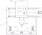
Fig. 1 is a schematic front view of the present invention;
fig. 2 is a schematic front view of the cross-sectional structure of the present invention;
fig. 3 is a schematic side view of the cross-sectional structure of the present invention;
fig. 4 is an enlarged schematic structural diagram of a in fig. 3 according to the present invention.
In the figure: 1. a control box; 2. a frame; 3. a support frame; 4. a clamping frame; 5. a handle; 6. a threaded sleeve; 7. a threaded rod; 8. a drive arm; 9. pressing into blocks; 10. lengthening a screw rod; 11. a screw rod sleeve; 12. a first rotary drive member; 13. a transmission frame; 14. a drive box; 15. a second rotary drive; 16. a limiting sleeve; 17. a threaded drive rod; 18. a threaded rack; 19. an adjusting bracket; 20. plasma cutting torch head.
Detailed Description
The technical solution in the embodiments of the present invention will be clearly and completely described below with reference to the accompanying drawings in the embodiments of the present invention. Based on the embodiments in the present invention, all other embodiments obtained by a person skilled in the art without creative work belong to the protection scope of the present invention.
Referring to fig. 1-4, the present invention provides an embodiment: a welding and cutting device based on hoisting and transporting equipment comprises a control box 1 and a rack 2, wherein the control box 1 is installed at the top end of the rack 2, a driving box 14 is installed on the outer wall of the control box 1, a supporting frame 3 is installed inside the rack 2 below the driving box 14, four groups of clamping frames 4 are installed at the top end of the supporting frame 3, transmission arms 8 are arranged inside the clamping frames 4, the transmission arms 8 are movably connected with the clamping frames 4, pressing blocks 9 are installed at the bottom ends of the transmission arms 8, the pressing blocks 9 are movably connected with the transmission arms 8, thread sleeves 6 are arranged at the top ends of the clamping frames 4 on one sides of the transmission arms 8, the thread sleeves 6 are movably connected with the clamping frames 4, threaded rods 7 are arranged inside the thread sleeves 6, the bottom ends of the threaded rods 7 are movably connected with the transmission arms 8, the threaded rods 7 are in threaded connection with the thread sleeves 6, and handles 5 are installed at the top ends of the threaded rods 7;
when the welding and cutting device is used, a steel plate of the hoisting and transporting equipment is placed on the surface of the support frame 3, the handle 5 is rotated, the handle 5 drives the threaded rod 7 to rotate under the support of the clamping frame 4, the threaded rod 7 drives the transmission arm 8 to rotate under the threaded fit of the threaded sleeve 6 and the threaded rod 7, the transmission arm 8 drives the pressing block 9 to move downwards, the steel plate of the hoisting and transporting equipment is clamped by the pressing block 9, the steel plate of the hoisting and transporting equipment is fixed under the clamping of the four groups of pressing blocks 9, the rapid clamping and fixing of the steel plate of the hoisting and transporting equipment by the welding and cutting device are realized, the clamping speed of the welding and cutting device is accelerated, and the working efficiency of the welding and cutting device is improved;
a lengthened lead screw 10 is arranged in the rack 2 below the support frame 3, a lead screw sleeve 11 is sleeved on the surface of the lengthened lead screw 10, the lead screw sleeve 11 is in threaded connection with the lengthened lead screw 10, a transmission frame 13 is arranged at the top end of the lead screw sleeve 11, the top end of the transmission frame 13 is connected with the support frame 3, a first rotary driving part 12 is arranged in the rack 2 on one side of the lead screw sleeve 11, the output end of the first rotary driving part 12 is connected with the lengthened lead screw 10, and the first rotary driving part 12 plays a role in power driving;
when the welding and cutting device is used, the first rotary driving piece 12 is opened, the first rotary driving piece 12 drives the lengthening screw rod 10 to rotate under the support of the rack 2, the lengthening screw rod 10 drives the screw rod sleeve 11 to move horizontally under the matching of the lengthening screw rod 10 and the screw rod sleeve 11, the screw rod sleeve 11 drives the transmission frame 13 to move horizontally, the transmission frame 13 drives the support frame 3 to move horizontally, so that the support frame 3 can be adjusted in the horizontal position, the welding and cutting device can conveniently cut and process a steel plate of the hoisting and transporting device, the welding and cutting device can conveniently drive and move a workpiece, and the convenience in use of the welding and cutting device is improved;
a threaded transmission rod 17 is arranged inside the driving box 14, a threaded frame 18 is arranged on the outer wall of the threaded transmission rod 17, an adjusting frame 19 is arranged on the inner wall of the threaded frame 18, a plasma cutting gun head 20 is arranged at the bottom end of the adjusting frame 19, four groups of limiting sleeves 16 are arranged inside the driving box 14 on one side of the adjusting frame 19, the limiting sleeves 16 are connected with the adjusting frame 19 in a sliding manner, a second rotary driving piece 15 is arranged inside the driving box 14 above the threaded transmission rod 17, and the output end of the second rotary driving piece 15 is connected with the threaded transmission rod 17;
during the use, through opening the second rotary driving part 15, the second rotary driving part 15 drives the screw thread transmission rod 17 to rotate, under the cooperation of the screw thread transmission rod 17 and the screw thread frame 18, the screw thread transmission rod 17 drives the screw thread frame 18 to move downwards, the screw thread frame 18 drives the adjusting frame 19 to move downwards, the limiting sleeve 16 carries out sliding support on the adjusting frame 19, the adjusting frame 19 drives the plasma cutting gun head 20 to move downwards, the height of the plasma cutting gun head 20 is adjusted, the height adjusting type processing of the welding cutting device is realized, and the rapid debugging and use of the welding cutting device are facilitated.
When the embodiment of the application is used: firstly, a steel plate of the hoisting and transporting equipment is placed on the surface of a support frame 3, a handle 5 is rotated, under the support of a clamping frame 4, the handle 5 drives a threaded rod 7 to rotate, under the thread matching of a threaded sleeve 6 and the threaded rod 7, the threaded rod 7 drives a transmission arm 8 to rotate, the transmission arm 8 drives a pressing block 9 to move downwards, the steel plate of the hoisting and transporting equipment is clamped by the pressing block 9, under the clamping of four groups of pressing blocks 9, the steel plate of the hoisting and transporting equipment is fixed, then, through opening a first rotary driving piece 12, under the support of a frame 2, the first rotary driving piece 12 drives an extension screw rod 10 to rotate, under the matching of the extension screw rod 10 and a screw rod sleeve 11, the extension screw rod 10 drives a screw rod sleeve 11 to move horizontally, the transmission frame 11 drives a transmission frame 13 to move horizontally, the support frame 3 is driven by the transmission frame 13 to move horizontally, so as to adjust the horizontal position of the support frame 3, make things convenient for welding cutting device to cut processing to the hoisting transportation equipment steel sheet, second rotary driving spare 15 is opened to the rethread, second rotary driving spare 15 drive screw thread transfer line 17 is rotatory, under the cooperation of screw thread transfer line 17 and screw thread frame 18, screw thread transfer line 17 drive screw thread frame 18 moves down, by screw thread frame 18 drive adjusting bracket 19 move down, stop collar 16 slides the support to adjusting bracket 19, drive plasma cutting rifle head 20 by adjusting bracket 19 and move down, come the height of plasma cutting rifle head 20 to adjust, accomplish welding cutting device's use work.
Claims (7)
1. The utility model provides a welding cutting device based on jack-up transportation equipment, includes control box (1) and frame (2), its characterized in that: control box (1) is installed on the top of frame (2), install drive box (14) on the outer wall of control box (1), frame (2) internally mounted of drive box (14) below has support frame (3), four group's holding frame (4) are installed on the top of support frame (3), the inside of holding frame (4) all is equipped with driving arm (8), briquetting (9) are all installed to the bottom of driving arm (8), holding frame (4) top of driving arm (8) one side all is equipped with thread bush (6), the inside of thread bush (6) all is equipped with threaded rod (7), and the bottom and driving arm (8) swing joint of threaded rod (7), handle (5) are all installed on the top of threaded rod (7).
2. The welding and cutting device based on the hoisting and transporting equipment as claimed in claim 1, wherein: the frame (2) internally mounted of support frame (3) below has extension lead screw (10), the surperficial cover of extension lead screw (10) is equipped with lead screw cover (11).
3. The welding and cutting device based on the hoisting and transporting equipment as claimed in claim 2, wherein: the top end of the screw rod sleeve (11) is provided with a transmission frame (13), and the top end of the transmission frame (13) is connected with the support frame (3).
4. The welding and cutting device based on the hoisting and transporting equipment as claimed in claim 2, wherein: a first rotary driving piece (12) is installed inside the rack (2) on one side of the screw rod sleeve (11), and the output end of the first rotary driving piece (12) is connected with the lengthened screw rod (10).
5. The welding and cutting device based on the hoisting and transporting equipment as claimed in claim 1, wherein: the plasma cutting torch is characterized in that a threaded transmission rod (17) is arranged inside the driving box (14), a threaded frame (18) is arranged on the outer wall of the threaded transmission rod (17), an adjusting frame (19) is installed on the inner wall of the threaded frame (18), and a plasma cutting torch head (20) is installed at the bottom end of the adjusting frame (19).
6. The welding and cutting device based on the hoisting and transporting equipment as claimed in claim 5, wherein: four groups of limiting sleeves (16) are arranged inside the driving box (14) on one side of the adjusting frame (19), and the limiting sleeves (16) are connected with the adjusting frame (19) in a sliding mode.
7. Welding and cutting device based on hoisting and transporting equipment according to claim 6, characterized in that: and a second rotary driving piece (15) is arranged in the driving box (14) above the threaded transmission rod (17).
Priority Applications (1)
| Application Number | Priority Date | Filing Date | Title |
|---|---|---|---|
| CN202221269213.0U CN217412776U (en) | 2022-05-25 | 2022-05-25 | Welding cutting device based on hoisting and transporting equipment |
Applications Claiming Priority (1)
| Application Number | Priority Date | Filing Date | Title |
|---|---|---|---|
| CN202221269213.0U CN217412776U (en) | 2022-05-25 | 2022-05-25 | Welding cutting device based on hoisting and transporting equipment |
Publications (1)
| Publication Number | Publication Date |
|---|---|
| CN217412776U true CN217412776U (en) | 2022-09-13 |
Family
ID=83189902
Family Applications (1)
| Application Number | Title | Priority Date | Filing Date |
|---|---|---|---|
| CN202221269213.0U Active CN217412776U (en) | 2022-05-25 | 2022-05-25 | Welding cutting device based on hoisting and transporting equipment |
Country Status (1)
| Country | Link |
|---|---|
| CN (1) | CN217412776U (en) |
-
2022
- 2022-05-25 CN CN202221269213.0U patent/CN217412776U/en active Active
Similar Documents
| Publication | Publication Date | Title |
|---|---|---|
| CN211540218U (en) | Front-end online machining mechanism for friction welding machine | |
| CN213105647U (en) | Boring and milling machining center for machining high-pressure pump body | |
| CN218311745U (en) | Dual-purpose laser cutting machine anchor clamps of board pipe | |
| CN217412776U (en) | Welding cutting device based on hoisting and transporting equipment | |
| CN211278124U (en) | Positioning fixture of automatic turn-over for machining | |
| CN217316538U (en) | Electric welding support for mechanical welding | |
| CN215787476U (en) | Low-power laser-induced CO2 electric arc hybrid welding equipment | |
| CN214921277U (en) | Welding device for thick steel plate of wind power tower | |
| CN210388890U (en) | Vertical fixed miniature bench vice | |
| CN114101844A (en) | Welding test panel groove cutting device | |
| CN213827454U (en) | Supporting and positioning device of plasma cutting machine | |
| CN219484624U (en) | Double-gun welding machine | |
| CN219599468U (en) | Automobile part machining tool table | |
| CN215146208U (en) | Welding device for metal product processing | |
| CN217096396U (en) | Welding fixing device for automatic welding machine | |
| CN211489857U (en) | Rectangular coordinate is cutting frock for manipulator | |
| CN114536246B (en) | Quick clamping device for mechanical manufacturing | |
| CN212217751U (en) | Drilling device for welding machine machining | |
| CN216858775U (en) | Novel sheet metal part welding clamp | |
| CN220660606U (en) | Circular workpiece clamping tool | |
| CN218692981U (en) | Clamping and feeding device of double-head edge rotating machine | |
| CN220761398U (en) | Large-table-board numerical control laser cutting machine support | |
| CN220372320U (en) | Angle steel cutting equipment convenient to adjust | |
| CN220838374U (en) | Butt-joint machine | |
| CN210817731U (en) | Metal band sawing machine with clamping device |
Legal Events
| Date | Code | Title | Description |
|---|---|---|---|
| GR01 | Patent grant | ||
| GR01 | Patent grant |