CN217399991U - External hanging connection structure of composite wall board - Google Patents
External hanging connection structure of composite wall board Download PDFInfo
- Publication number
- CN217399991U CN217399991U CN202221379707.4U CN202221379707U CN217399991U CN 217399991 U CN217399991 U CN 217399991U CN 202221379707 U CN202221379707 U CN 202221379707U CN 217399991 U CN217399991 U CN 217399991U
- Authority
- CN
- China
- Prior art keywords
- hanging
- welding screw
- assembly
- wall panel
- connecting piece
- Prior art date
- Legal status (The legal status is an assumption and is not a legal conclusion. Google has not performed a legal analysis and makes no representation as to the accuracy of the status listed.)
- Active
Links
Images


Classifications
-
- Y—GENERAL TAGGING OF NEW TECHNOLOGICAL DEVELOPMENTS; GENERAL TAGGING OF CROSS-SECTIONAL TECHNOLOGIES SPANNING OVER SEVERAL SECTIONS OF THE IPC; TECHNICAL SUBJECTS COVERED BY FORMER USPC CROSS-REFERENCE ART COLLECTIONS [XRACs] AND DIGESTS
- Y02—TECHNOLOGIES OR APPLICATIONS FOR MITIGATION OR ADAPTATION AGAINST CLIMATE CHANGE
- Y02A—TECHNOLOGIES FOR ADAPTATION TO CLIMATE CHANGE
- Y02A30/00—Adapting or protecting infrastructure or their operation
- Y02A30/24—Structural elements or technologies for improving thermal insulation
- Y02A30/244—Structural elements or technologies for improving thermal insulation using natural or recycled building materials, e.g. straw, wool, clay or used tires
Abstract
The utility model discloses a composite wallboard external hanging connection structure, which comprises a wallboard, a structural beam and a hanging component; the wall board is provided with a vertical keel; the structural beam comprises a first steel beam and a second steel beam which are vertically arranged at intervals; the wall plate is connected with the structural beam through the hanging assembly, and the position of the wall plate in the length direction, the width direction and/or the height direction of the structural beam can be adjusted; the hanging component comprises a first hanging component and a second hanging component; one end of the first hanging component is fixedly connected with the upper end of the vertical keel, and the other end of the first hanging component is fixedly connected with the lower flange of the first steel beam; the one end that the second articulates the subassembly is connected fixedly with the lower extreme of vertical fossil fragments, and the other end that the first subassembly that articulates is connected fixedly with the last flange of second girder steel. The utility model discloses improved composite wall panel's mounting structure, improved the external convenience of composite wall panel, the atress is reliable, has promoted the efficiency of construction.
Description
Technical Field
The utility model relates to an assembly type structure technical field especially relates to an external connection structure of composite wall panel.
Background
The construction industry is the prop industry of China, and the development of the construction industry of China in recent years has the problems of high resource consumption, generation of a large amount of construction waste, noise pollution, difficulty in control of construction quality and the like, and meanwhile, along with the improvement of national education degree, the labor cost gradually rises, and the problem of serious 'barren civil engineering' can be met in the later period. Therefore, the green assembled steel structure building is vigorously developed, and the important influence on improving the building quality in China and optimizing the production industry of the building industry is achieved. Relevant construction, design, construction units are suggested, when the construction strength of self enterprises is improved, the research on steel structure building products is enhanced, the quality of the steel structure products is optimized by enhancing the self construction technology, so that the self construction can be ensured to be capable of following the development and progress of the construction industry era, and the sustainable development of each item of construction economic activity is promoted. While the globalization of resources is emphasized, the green assembly type steel structure building system grasps the characteristics of environmental protection construction and green industry, and the structure industry is widely utilized by virtue of the advantages of energy conservation, environmental protection, durability, practicability and the like.
At present, composite wall panels are commonly used in steel structure residential systems. The light steel keel externally hung composite wallboard is a novel composite wallboard externally hung on a steel frame, and is formed by taking cold-formed thin-wall steel as a framework, taking keels as boards such as paper-covered gypsum boards or fiber cement pressure plates and the like, and filling heat-preservation and heat-insulation materials such as rock wool or glass fiber cotton and the like. The externally-hung composite wallboard has the advantages of light dead weight, factory manufacturing of components, dry construction, environmental protection, energy conservation, cold bridge prevention and the like.
The existing wall panel external connection structure comprises an external wall panel unit, a bottom mounting piece and a top mounting piece, wherein the external wall panel unit is hung on a building main body; the bottom mounting piece is arranged on a floor slab of the same floor, supports the external wallboard unit and clamps and fixes the external wallboard unit; the top installed part is installed on the structural beam of the roof slab department of same floor, and the top installed part presss from both sides to establish and is fixed in the externally-hung wallboard unit. However, during construction, the hanging positions of the external wall panel unit and the building main body are relatively fixed, and due to machining errors of all parts, the mounting positions of the wall panels cannot be adjusted during assembly, alignment is difficult, and construction efficiency is reduced.
SUMMERY OF THE UTILITY MODEL
The utility model discloses a main aim at provides an external connection structure of composite wall panel aims at improving the external convenience of composite wall panel to improve the efficiency of construction.
In order to achieve the above object, the utility model provides an external connection structure of composite wall panel, include:
a wall panel having vertical keels;
the structural beam comprises a first steel beam and a second steel beam which are vertically arranged at intervals; and
the hanging assembly is used for connecting the wall plate with the structural beam, and the position of the wall plate in the length direction, the width direction and the height direction of the structural beam can be adjusted;
the hanging assembly comprises a first hanging assembly and a second hanging assembly; one end of the first hanging component is fixedly connected with the upper end of the vertical keel, and the other end of the first hanging component is fixedly connected with the lower flange of the first steel beam; the one end that the second articulated the subassembly with the lower extreme of vertical keel is connected fixedly, the first other end that articulates the subassembly with the last flange of second girder steel is connected fixedly.
Optionally, the first hooking assembly comprises a first connecting plate, a first connecting piece, a first adjusting and fastening assembly and a first locking assembly; one side of the first connecting plate is fixed with the upper end of the vertical keel, the other side of the first connecting plate is connected with the first connecting piece in a position-adjustable mode through the first adjusting and fastening assembly, and the first connecting piece is fixedly locked with the lower flange of the first steel beam through the first locking assembly.
Optionally, a first waist-shaped hole extending along the length direction of the first steel beam is formed in the first connecting piece;
first adjustment fastener includes first welding screw and first adjustment fastening nut group, first welding screw's one end with first connecting plate welded fastening, first welding screw's the other end is worn to establish first waist shape hole and is passed through first adjustment fastening nut group with first connecting piece locking is fixed, so that first connecting plate is in the adjustable setting in position on the length direction of first girder steel.
Optionally, a first through hole is formed in the first connecting piece;
the first locking assembly comprises a second welding screw and a second adjusting and fastening nut group, one end of the second welding screw is fixedly welded to the lower flange of the first steel beam, and the other end of the first welding screw penetrates through the first through hole and is fixedly locked to the first connecting piece through the second adjusting and fastening nut group.
Optionally, the second hooking assembly comprises a second connecting plate, a second connecting piece, a second adjusting and fastening assembly and a second locking assembly;
one side of the second connecting plate is fixed with the lower end of the vertical keel, the other side of the second connecting plate is connected with the second connecting piece in a position-adjustable mode through the second adjusting and fastening assembly, and the second connecting piece is fixed with the upper flange of the second steel beam in a locking mode through the second locking assembly.
Optionally, a second waist-shaped hole extending along the length direction of the second steel beam is formed in the second connecting piece;
the second adjustment fastener includes third welding screw and third adjustment fastening nut group, the one end of third welding screw with second connecting plate welded fastening, the other end of third welding screw is worn to establish second waist shape hole and is passed through third adjustment fastening nut group with second connecting piece locking is fixed, so that the second connecting plate is in the adjustable setting of position on the length direction of second girder steel.
Optionally, a second through hole is formed in the second connecting piece;
the second locking assembly comprises a fourth welding screw and a fourth adjusting fastening nut group, one end of the fourth welding screw is fixedly welded to the upper flange of the second steel beam, and the other end of the fourth welding screw penetrates through the second through hole and passes through the fourth adjusting fastening nut group and the second connecting piece to be locked and fixed.
Optionally, the first connecting plate and the second connecting plate are both arranged in a T shape; and/or
The first connecting piece and the second connecting piece are arranged in a triangular mode.
Optionally, the lengths of the first waist-shaped hole and the second waist-shaped hole are both 30-35 mm.
Optionally, the first connecting piece and the second connecting piece are both provided with stiffening ribs.
In the technical scheme of the utility model, the external hanging connection structure of the composite wallboard comprises a wallboard, a structural beam and a hanging component; the wall board is provided with a vertical keel; the structural beam comprises a first steel beam and a second steel beam which are vertically arranged at intervals; the wall plate is connected with the structural beam through the hanging connection assembly, and the position of the wall plate in the length direction, the width direction and the height direction of the structural beam can be adjusted; the hanging component comprises a first hanging component and a second hanging component; one end of the first hanging component is fixedly connected with the upper end of the vertical keel, and the other end of the first hanging component is fixedly connected with the lower flange of the first steel beam; the one end that the second articulates the subassembly is connected fixedly with the lower extreme of vertical fossil fragments, and the other end that the first subassembly that articulates is connected fixedly with the last flange of second girder steel. So, when the construction, the accessible articulates the subassembly and finely tunes the mounted position of wallboard on length direction and/or width direction and/or direction of height, is convenient for counterpoint, under the reliable prerequisite of guaranteeing the atress, has greatly improved the external convenience of composite wall panel, has promoted the efficiency of construction.
Drawings
In order to more clearly illustrate the embodiments of the present invention or the technical solutions in the prior art, the drawings needed to be used in the description of the embodiments or the prior art will be briefly described below, it is obvious that the drawings in the following description are only some embodiments of the present invention, and for those skilled in the art, other drawings can be obtained according to the structures shown in the drawings without creative efforts.
FIG. 1 is a schematic structural view of an embodiment of the composite wall panel external connection structure of the present invention;
fig. 2 is a schematic structural view illustrating the installation of the first connecting plate and the first adjusting and fastening assembly in an embodiment of the external connection structure of the composite wall panel of the present invention;
fig. 3 is a schematic structural view illustrating the installation of a second connecting plate and a second adjusting and fastening component in an embodiment of the external connecting structure of composite wall panels according to the present invention;
FIG. 4 is a first cross-sectional view of a first connector in an embodiment of the present invention;
FIG. 5 is a second cross-sectional view of the first connector in an embodiment of the composite wall panel external connection structure of the present invention;
FIG. 6 is a third cross-sectional view of the first connector in an embodiment of the composite wall panel external connection structure of the present invention;
fig. 7 is a first cross-sectional view of a second connecting member in an embodiment of the composite wall panel external connection structure of the present invention;
fig. 8 is a second cross-sectional view of a second connecting member in an embodiment of the composite wall panel external connection structure of the present invention;
fig. 9 is a third cross-sectional view of the second connecting member in an embodiment of the external connection structure of composite wall panel according to the present invention.
The reference numbers illustrate:
10. a wallboard; 20. a structural beam; 30. a hooking component; 101. a vertical keel; 31. a first hooking component; 32. a second hooking component; 311. a first connecting plate; 312. a first connecting member; 313. a first adjustment fastening assembly; 314. a first locking assembly; 312a, a first waist-shaped aperture; 312b, a first via hole; 321. a second connecting plate; 322. a second connecting member; 323. a second adjustment fastening assembly; 324. a second locking assembly; 322a, a second waist-shaped hole; 322b, a second through hole; 315. a stiffening rib; 40. overlapping the floor slabs; 50. a floor layer.
The realization, the functional characteristics and the advantages of the utility model are further explained by combining the embodiment and referring to the attached drawings.
Detailed Description
The technical solutions in the embodiments of the present invention will be described clearly and completely with reference to the accompanying drawings in the embodiments of the present invention, and it is obvious that the described embodiments are only some embodiments of the present invention, not all embodiments. Based on the embodiments in the present invention, all other embodiments obtained by a person skilled in the art without creative efforts belong to the protection scope of the present invention.
It should be noted that, if directional indications (such as upper, lower, left, right, front and rear … …) are involved in the embodiment of the present invention, the directional indications are only used to explain the relative position relationship between the components, the motion situation, etc. in a specific posture (as shown in the drawings), and if the specific posture is changed, the directional indications are changed accordingly.
In addition, if there is a description relating to "first", "second", etc. in the embodiments of the present invention, the description of "first", "second", etc. is for descriptive purposes only and is not to be construed as indicating or implying relative importance or implicitly indicating the number of technical features indicated. Thus, a feature defined as "first" or "second" may explicitly or implicitly include at least one such feature. In addition, if appearing throughout the text, "and/or" is meant to include three juxtaposed aspects, taking "A and/or B" as an example, including either the A aspect, or the B aspect, or both A and B satisfied aspects. In addition, the technical solutions in the embodiments may be combined with each other, but it must be based on the realization of those skilled in the art, and when the technical solutions are contradictory or cannot be realized, the combination of the technical solutions should not be considered to exist, and is not within the protection scope of the present invention.
The utility model provides a composite wall panel joins externally the joint construction, especially the joint construction of the compound externally-hung wallboard of light gauge steel, here is unlimited.
Referring to fig. 1 to 3, in an embodiment of the present invention, the external hanging connection structure of composite wall panel comprises a wall panel 10, a structural beam 20 and a hanging assembly 30; the wall panel 10 has vertical keels 101; the structural beam 20 comprises a first steel beam and a second steel beam which are vertically arranged at intervals; the wall plate 10 is connected with the structural beam 20 through the hitching assembly 30, and the position of the wall plate 10 in the length direction and/or width direction and/or height direction of the structural beam 20 can be adjusted; the hitch assembly 30 includes a first hitch assembly 31 and a second hitch assembly 32; one end of the first hanging component 31 is fixedly connected with the upper end of the vertical keel 101, and the other end of the first hanging component 31 is fixedly connected with the lower flange of the first steel beam; one end of the second hanging component 32 is fixedly connected with the lower end of the vertical keel 101, and the other end of the first hanging component 31 is fixedly connected with the upper flange of the second steel beam.
Wherein, first girder steel is located the upper strata of building, and the second girder steel is located the lower floor of building. It should be noted that after the composite floor slab 40 of the building and the external connecting structure of the composite wall panel are integrally assembled, the cast-in-place floor slab 50 can be cast and molded above the composite floor slab.
In this embodiment, each of the first and second hooking assemblies 31 and 32 may include a connecting plate, a supporting plate, a connecting member, a locking member, and the like, which are not limited herein. The installation position can be adjusted by arranging strip-shaped through holes or strip-shaped grooves on the parts of the hooking assembly 30 and sliding the parts by matching with locking parts such as bolts or screws, and the extension directions of the strip-shaped through holes and the strip-shaped grooves can be the length direction, the width direction or the height direction of the structural beam 20, so that the installation position of the wallboard 10 can be adjusted in the length direction, the width direction and/or the height direction of the structural beam 20.
It can be understood that, during construction, the installation position of the wall board 10 in the length direction and/or the width direction and/or the height direction can be finely adjusted through the hanging component 30, so that alignment is facilitated, the convenience of the external hanging of the composite wall board 10 is greatly improved on the premise of ensuring reliable stress, and the construction efficiency is improved.
Referring to fig. 1, in an embodiment, the first hooking component 31 may include a first connecting plate 311, a first connecting member 312, a first adjusting fastening component 313 and a first locking component 314; one side of the first connecting plate 311 is fixed to the upper end of the vertical keel 101, the other side of the first connecting plate 311 is connected to the first connecting member 312 in an adjustable manner through a first adjusting and fastening assembly 313, and the first connecting member 312 is fixed to the lower flange of the first steel beam in a locked manner through a first locking assembly 314.
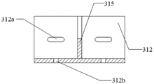
Referring to fig. 4 to 6, in the present embodiment, the first connecting member 312 is provided with a first kidney-shaped hole 312a extending along the length direction of the first steel beam; the first adjusting fastener may include a first welding screw and a first adjusting fastening nut set, one end of the first welding screw is welded and fixed to the first connecting plate 311, and the other end of the first welding screw penetrates through the first waist-shaped hole 312a and is locked and fixed to the first connecting member 312 through the first adjusting fastening nut set, so that the position of the first connecting plate 311 in the length direction of the first steel beam is adjustable.
Further, a first through hole 312b is formed on the first connecting member 312; the first locking component 314 may include a second welding screw and a second adjusting fastening nut set, one end of the second welding screw is welded and fixed to the lower flange of the first steel beam, and the other end of the first welding screw penetrates through the first through hole 312b and is locked and fixed to the first connecting component 312 through the second adjusting fastening nut set.
During construction, a first welding screw may be pre-installed, and as shown in fig. 2, welded to the first connection plate 311; a second welding screw can be pre-installed and welded on the lower flange of the first steel beam; referring to fig. 1, the first connection plate 311 is then connected to the vertical keel 101 of the light gauge steel composite wall panel 10, the second connection member 322 is connected to the first connection plate 311 by a first welding screw and fixed by a first adjusting fastening nut set, and the second connection member 322 is connected to the lower flange of the steel frame structural beam 20 by a second welding screw and fixed by a second fastening nut set.
Referring mainly to fig. 1, in an embodiment, the second hooking assembly 32 may include a second connecting plate 321, a second connecting member 322, a second adjusting fastener assembly 323, and a second locking assembly 324; one side of the second connecting plate 321 is fixed to the lower end of the vertical keel 101, the other side of the second connecting plate 321 is connected to the second connecting member 322 in an adjustable manner through a second adjusting and fastening assembly 323, and the second connecting member 322 is fixed to the upper flange of the second steel beam through a second locking assembly 324 in a locked manner.
Referring to fig. 7 to 9, in the present embodiment, the second connecting member 322 is provided with a second kidney-shaped hole 322a extending along the length direction of the second steel beam; the second adjustment fastener comprises a third welding screw and a third adjustment fastening nut group, one end of the third welding screw is fixedly welded with the second connecting plate 321, and the other end of the third welding screw penetrates through the second waist-shaped hole 322a and is fixedly locked with the second connecting piece 322 through the third adjustment fastening nut group, so that the second connecting plate 321 can be adjustably arranged in the length direction of the second steel beam.
Further, a second through hole 322b is provided on the second connecting member 322; the second locking assembly 324 may include a fourth welding screw and a fourth adjusting fastening nut set, one end of the fourth welding screw is welded and fixed to the upper flange of the second steel beam, and the other end of the fourth welding screw penetrates the second through hole 322b and is locked and fixed to the second connecting member 322 through the fourth adjusting fastening nut set.
During construction, a third welding screw may be pre-installed, and as shown in fig. 3, welded to the second connection plate 321; a fourth welding screw can be pre-installed and welded on the upper flange of the second steel beam; referring to fig. 1, the second connecting plate 321 is then connected to the vertical keel 101 of the composite wall panel 10, the second connecting member 322 is disposed below the end of the second connecting plate 321, connected to the second connecting plate 321 through a third welding screw, and fixed through a third adjusting fastening nut set, and the second connecting member 322 is connected to the upper flange of the steel frame structural beam 20 through a fourth welding screw, and fixed through a fourth fastening nut set.
In this embodiment, the first connecting plate 311 and the second connecting plate 321 may be welded to the vertical keel 101 in advance, the positions are determined by the positions of the vertical keels, the number of the connecting nodes may be determined according to the size of the wall panel 10, and the adjustable installation of the wall panel 10 is realized by the first connecting member 312 and the second connecting member 322. For example: when the width of the wall panel 10 is 4200mm, the vertical joists 101 may be arranged every 600mm, and the connectors may be welded to the second and seventh vertical joists 101, and then the horizontal spacing of the connectors may be 3000 m. For another example: when the width of wallboard 10 is 6000mm, vertical keel 101 can be arranged according to per 600mm, and the connecting piece can be welded on second way, sixth way and tenth way vertical keel 101, then the horizontal interval of connecting piece is 2400 m.
Referring to fig. 5 and 8, in the present embodiment, the first waist-shaped hole 312a and the second waist-shaped hole 322a each have a length of 30 to 35 mm. So, can satisfy connecting piece joint strength while, minimize the material quantity to it is adjustable to realize wallboard 10 mounted position.
The number of the first through holes 312b and the second through holes 322b may be four, which is not limited herein.
It should be noted that, the above embodiment details how to implement the adjustable installation of the wall panel 10 in the length direction of the structural beam 20, and as to how to implement the adjustable installation of the wall panel 10 in the width direction and the height direction of the structural beam 20, the specific adjustable installation structure thereof may refer to the above contents, and the adjustment principle is the same as the principle of the above technical solution, and therefore, the details are not described here.
Further, referring to fig. 2 and 3, in an embodiment, the first connecting plate 311 and the second connecting plate 321 may each be disposed in a T shape; referring to fig. 4 and 7, the first and second connectors 312 and 322 may each be triangularly shaped. Thus, the external wall panel 10 can be conveniently hung, and the integral stress requirement can be met.
Referring to fig. 4 and 7, the first connecting member 312 and the second connecting member 322 may be respectively provided with a stiffening rib 315, and the stiffening rib 315 may be disposed obliquely to improve the supporting strength of the connecting members, so as to further improve the stability of the external connection structure of the composite wall panel.
The above is only the optional embodiment of the present invention, and not the scope of the present invention is limited thereby, all the equivalent structure changes made by the contents of the specification and the drawings are utilized under the inventive concept of the present invention, or the direct/indirect application in other related technical fields is included in the patent protection scope of the present invention.
Claims (10)
1. A composite wall panel joins externally constructs characterized in that includes:
a wall panel having vertical keels;
the structural beam comprises a first steel beam and a second steel beam which are vertically arranged at intervals; and
the hanging assembly is used for connecting the wall plate with the structural beam, and the position of the wall plate in the length direction, the width direction and the height direction of the structural beam can be adjusted;
the hanging assembly comprises a first hanging assembly and a second hanging assembly; one end of the first hanging component is fixedly connected with the upper end of the vertical keel, and the other end of the first hanging component is fixedly connected with the lower flange of the first steel beam; the one end that the second articulated the subassembly with the lower extreme of vertical keel is connected fixedly, the first other end that articulates the subassembly with the last flange of second girder steel is connected fixedly.
2. The composite wallboard externally-hung connection configuration of claim 1, wherein said first hooking assembly comprises a first connection plate, a first connector, a first adjustment fastening assembly and a first locking assembly; one side of the first connecting plate is fixed with the upper end of the vertical keel, the other side of the first connecting plate is connected with the first connecting piece in a position-adjustable mode through the first adjusting and fastening assembly, and the first connecting piece is fixedly locked with the lower flange of the first steel beam through the first locking assembly.
3. The composite wallboard external hanging connection structure of claim 2, wherein the first connection piece is provided with a first waist-shaped hole extending along the length direction of the first steel beam;
first adjustment fastener includes first welding screw and first adjustment fastening nut group, first welding screw's one end with first connecting plate welded fastening, first welding screw's the other end is worn to establish first waist shape hole and is passed through first adjustment fastening nut group with first connecting piece locking is fixed, so that first connecting plate is in the adjustable setting in position on the length direction of first girder steel.
4. The composite wall panel external hanging connection structure of claim 3, wherein the first connecting member is provided with a first through hole;
the first locking assembly comprises a second welding screw and a second adjusting and fastening nut group, one end of the second welding screw is fixedly welded to the lower flange of the first steel beam, and the other end of the first welding screw penetrates through the first through hole and passes through the second adjusting and fastening nut group and the first connecting piece to be locked and fixed.
5. The composite wall panel external hanging connection structure of claim 4, wherein the second hanging assembly comprises a second connecting plate, a second connecting piece, a second adjusting fastening assembly and a second locking assembly;
one side of the second connecting plate is fixed with the lower end of the vertical keel, the other side of the second connecting plate is connected with the second connecting piece in a position-adjustable mode through the second adjusting and fastening assembly, and the second connecting piece is fixed with the upper flange of the second steel beam in a locking mode through the second locking assembly.
6. The composite wall panel external hanging connection structure of claim 5, wherein the second connecting piece is provided with a second kidney-shaped hole extending along the length direction of the second steel beam;
the second adjustment fastener includes third welding screw and third adjustment fastening nut group, the one end of third welding screw with second connecting plate welded fastening, the other end of third welding screw is worn to establish second waist shape hole and is passed through third adjustment fastening nut group with second connecting piece locking is fixed, so that the second connecting plate is in the adjustable setting of position on the length direction of second girder steel.
7. The composite wall panel exterior hanging connection structure of claim 6, wherein said second connector is provided with a second through hole;
the second locking assembly comprises a fourth welding screw and a fourth adjusting fastening nut group, one end of the fourth welding screw is fixedly welded to the upper flange of the second steel beam, and the other end of the fourth welding screw penetrates through the second through hole and passes through the fourth adjusting fastening nut group and the second connecting piece to be locked and fixed.
8. The composite wall panel external connection structure of claim 6, wherein the first connection plate and the second connection plate are both T-shaped; and/or
The first connecting piece and the second connecting piece are arranged in a triangular mode.
9. The composite wall panel external hanging connection structure of claim 6, wherein the length of the first waist-shaped hole and the length of the second waist-shaped hole are both 30-35 mm.
10. The composite wallboard externally hung connecting structure of claim 6, wherein each of said first connecting member and said second connecting member is provided with a stiffening rib.
Priority Applications (1)
| Application Number | Priority Date | Filing Date | Title |
|---|---|---|---|
| CN202221379707.4U CN217399991U (en) | 2022-06-01 | 2022-06-01 | External hanging connection structure of composite wall board |
Applications Claiming Priority (1)
| Application Number | Priority Date | Filing Date | Title |
|---|---|---|---|
| CN202221379707.4U CN217399991U (en) | 2022-06-01 | 2022-06-01 | External hanging connection structure of composite wall board |
Publications (1)
| Publication Number | Publication Date |
|---|---|
| CN217399991U true CN217399991U (en) | 2022-09-09 |
Family
ID=83145577
Family Applications (1)
| Application Number | Title | Priority Date | Filing Date |
|---|---|---|---|
| CN202221379707.4U Active CN217399991U (en) | 2022-06-01 | 2022-06-01 | External hanging connection structure of composite wall board |
Country Status (1)
| Country | Link |
|---|---|
| CN (1) | CN217399991U (en) |
-
2022
- 2022-06-01 CN CN202221379707.4U patent/CN217399991U/en active Active
Similar Documents
| Publication | Publication Date | Title |
|---|---|---|
| CN217399991U (en) | External hanging connection structure of composite wall board | |
| CN212317230U (en) | Wall body mounting structure of prefabricated building | |
| CN112282047A (en) | Connecting structure and connecting method for assembled composite floor slab and composite wallboard | |
| CN114856029A (en) | External hanging connection structure of composite wall board | |
| CN108755933B (en) | Prefabricated balcony convenient to installation is fixed | |
| CN212376010U (en) | Assembled concrete house structure | |
| CN213087281U (en) | Unit type heat-preservation and decoration integrated plate outer wall system of metal panel | |
| CN209308459U (en) | A kind of structure increasing partition wall newly on existing building floor | |
| CN210002670U (en) | assembled ceiling structure | |
| CN210369983U (en) | High-rise building segmentation construction protection canopy | |
| CN112127515A (en) | Connecting device for precast concrete external wall panels | |
| CN215759888U (en) | Autoclaved aerated concrete floor structure | |
| CN214117185U (en) | Add furred ceiling mounting structure after | |
| CN212897036U (en) | Assembled curtain wall used between window wall system layers | |
| CN219033627U (en) | Closed connection structure for side wall boards of I-beam of steel structure building | |
| CN217759582U (en) | Hidden sliding structure for steel beam | |
| JPH0339529Y2 (en) | ||
| CN216196651U (en) | Building templates is reentrant corner connecting piece for reinforcerment system | |
| CN216340192U (en) | Composite heat-insulation board with supporting and reinforcing bone structure | |
| CN215802471U (en) | Prefabricated partition wall connection structure convenient to installation | |
| CN218323860U (en) | U-shaped template profile combining aluminum mold and wood mold | |
| CN211775782U (en) | Frame body for frame or beam of building formwork | |
| CN214272508U (en) | T-shaped wallboard connecting node | |
| CN217205296U (en) | Concrete beam plastic formwork for building construction | |
| RU120667U1 (en) | CONNECTING ELEMENT INSTALLED BETWEEN THE FACING FACADE FACING ELEMENT AND THE BUILDING WALL |
Legal Events
| Date | Code | Title | Description |
|---|---|---|---|
| GR01 | Patent grant | ||
| GR01 | Patent grant |