CN217398700U - Industrial sewage treatment pond - Google Patents
Industrial sewage treatment pond Download PDFInfo
- Publication number
- CN217398700U CN217398700U CN202220858106.5U CN202220858106U CN217398700U CN 217398700 U CN217398700 U CN 217398700U CN 202220858106 U CN202220858106 U CN 202220858106U CN 217398700 U CN217398700 U CN 217398700U
- Authority
- CN
- China
- Prior art keywords
- tank
- water
- sludge
- pond
- sewage treatment
- Prior art date
- Legal status (The legal status is an assumption and is not a legal conclusion. Google has not performed a legal analysis and makes no representation as to the accuracy of the status listed.)
- Active
Links
Images


Classifications
-
- Y—GENERAL TAGGING OF NEW TECHNOLOGICAL DEVELOPMENTS; GENERAL TAGGING OF CROSS-SECTIONAL TECHNOLOGIES SPANNING OVER SEVERAL SECTIONS OF THE IPC; TECHNICAL SUBJECTS COVERED BY FORMER USPC CROSS-REFERENCE ART COLLECTIONS [XRACs] AND DIGESTS
- Y02—TECHNOLOGIES OR APPLICATIONS FOR MITIGATION OR ADAPTATION AGAINST CLIMATE CHANGE
- Y02E—REDUCTION OF GREENHOUSE GAS [GHG] EMISSIONS, RELATED TO ENERGY GENERATION, TRANSMISSION OR DISTRIBUTION
- Y02E50/00—Technologies for the production of fuel of non-fossil origin
- Y02E50/30—Fuel from waste, e.g. synthetic alcohol or diesel
Abstract
The utility model discloses an industrial sewage treatment tank, which comprises an anaerobic tank and a buffer tank which are combined and arranged adjacently, wherein the bottom of the anaerobic tank is provided with a conical reactor, one side of the bottom of the anaerobic tank is provided with a sludge collecting pit, the anaerobic tank is also internally provided with a low-speed plug flow device, and a water distributor is arranged above the anaerobic tank; the anaerobic tank is characterized in that a three-phase separator is arranged in the buffer tank, a gas-phase separation port and a liquid-phase separation port which correspond to the three-phase separator in the buffer tank are respectively provided with a gas-guide tube and a water-collecting tank, and the bottom of the buffer tank is provided with a sludge return port communicated with the anaerobic tank. The utility model discloses a sewage treatment structure that anaerobism pond and buffering pond combined together to set up the low-speed impeller in order to improve the stirring effect in the pond in the anaerobism pond, simultaneously, set up the triphase separator in the buffering pond, can reduce the degree that mud runs off in the anaerobism pond, in addition, through to the partial water recycling after handling, can prevent sludge reflux mouth and low-speed impeller department the condition that the long-pending mud blockked up from appearing.
Description
Technical Field
The utility model relates to a sewage treatment technical field especially relates to an industrial sewage treatment pond.
Background
The industrial sewage contains a large amount of organic pollutants, the direct discharge can cause serious pollution to the environment, the anaerobic bacteria fermentation treatment is needed to convert the organic pollutants into biogas, and the biogas is discharged and collected, and meanwhile, the separated sludge and water are discharged and collected. Traditional sewage treatment pond, stirring effect in its pond is relatively poor, and reaction efficiency is lower, and packs fewly, and a large amount of residues of easy deposit of bottom of the pool, moreover, when the clear water of discharge upper strata, cause the mud in the treatment pond to run off easily.
SUMMERY OF THE UTILITY MODEL
In order to solve the problems, the utility model provides an industrial sewage treatment pond adopts the sewage treatment structure that anaerobism pond and buffering pond combined together to set up the stirring effect of low-speed impeller in order to improve the pond in the anaerobism pond, simultaneously, set up the triphase separator in the buffering pond, can reduce the degree that mud runs off in the anaerobism pond, in addition, through to the part water recycling after handling, can prevent mud backward flow mouth and low-speed impeller department the condition that long-pending mud blockked up from appearing.
The technical scheme of the utility model as follows:
an industrial sewage treatment tank comprises an anaerobic tank and a buffer tank which are combined and arranged adjacently, wherein a conical reactor is arranged at the bottom of the anaerobic tank, a sludge collecting pit is arranged at one side of the bottom of the anaerobic tank, a low-speed impeller is also arranged in the anaerobic tank, and a water distributor is arranged above the anaerobic tank; the anaerobic tank is characterized in that a three-phase separator is arranged in the buffer tank, a gas-phase separation port and a liquid-phase separation port which correspond to the three-phase separator in the buffer tank are respectively provided with a gas-guide tube and a water-collecting tank, and the bottom of the buffer tank is provided with a sludge return port communicated with the anaerobic tank.
The working principle of the technical scheme is as follows:
the utility model discloses a sewage treatment structure that anaerobism pond and buffer pool combined together sets up the low-speed impeller in the anaerobism pond, promote the sewage in the anaerobism pond through the low-speed impeller and carry out slow flow, form the turbulent flow, can effectively improve the stirring effect in the pond, strengthen reaction efficiency, in addition, still set up the three-phase separator in the buffer pool, the marsh gas and the water that will separate out are collected respectively, the mud separation that carries the aquatic simultaneously blocks down, flow back to the anaerobism pond through the mud backward flow mouth in, can reduce the degree that mud runs off in the anaerobism pond.
In a further technical scheme, the water distributor is a siphon type pulse water distributor, a water distribution pipe of the water distributor extends to the bottom of the anaerobic tank and is located right above the reactor, the water distributor is simple and convenient to operate and has the functions of hydraulic stirring and water distribution uniformity, the pipe diameter can be determined according to the specific design flow, high efficiency, energy conservation, rapid water distribution and convenient maintenance can be realized, water distribution is performed at the bottom of the anaerobic tank, the sludge concentration and muddy water mixing effect are ensured, the generation of inflammable and malodorous gases is controlled, so that under a better treatment effect, the retention time is shortened, the tank capacity is reduced, and the investment cost is reduced.
In a further technical scheme, the end part of a water distribution pipe of the water distributor is in a horn shape.
In a further technical scheme, the three-phase separator comprises a plurality of reflecting plates which are arranged in a zigzag manner, two adjacent reflecting plates are connected at wave crests, openings are formed at wave troughs, air chambers are formed between the two adjacent reflecting plates at the wave crests, and first air guide pipes communicated with the air chambers are arranged in the buffer tank; the top of reflecting plate is equipped with water collection platform, be equipped with the overflow mouth between water collection platform's the side and the inner wall of buffer pool, water collection platform's top is equipped with the water catch bowl that extends to the buffer pool outside.
Sewage to be treated flows into the anaerobic tank from the bottom of the anaerobic tank to be mixed and contacted with sludge in a sludge layer, microorganisms in the sludge decompose organic matters in the sewage to convert the organic matters into methane, the methane is continuously discharged in the form of micro bubbles, the micro bubbles are continuously combined in the ascending process to gradually form larger bubbles, sludge liquid with thinner sludge concentration is formed at the upper part of a sludge bed due to the stirring of the methane, the sludge liquid and water rise into a three-phase separator, when the methane touches a reflecting plate at the lower part of the three-phase separator, the methane is folded to the periphery of the reflecting plate and then passes through a water layer to enter a gas chamber, the methane concentrated in the gas chamber is guided out by a first guide pipe, solid-liquid mixed liquid is reflected to enter a settling zone of the three-phase separator, namely a zone between the reflecting plate and a water collecting platform, the sludge in the sewage is flocculated, particles are gradually increased, and are settled under the action of gravity and slide back into the anaerobic tank through a sludge return port, a large amount of sludge is accumulated in the reaction zone of the anaerobic tank, and treated effluent separated from the sludge overflows from an overflow gap of the settling zone and is discharged through a water collecting tank.
In a further technical scheme, a circulating pump is arranged above the water collecting platform in the buffer pool, a water outlet of the circulating pump is connected with a circulating pipe, a water inlet connected with the circulating pipe is formed in the water distributor, partial treated water is utilized by additionally arranging the circulating pump, sewage is diluted, and the condition that sludge is accumulated and blocked at a sludge backflow port and a low-speed impeller can be prevented.
In a further technical scheme, the height of the top surface of the water collecting platform is gradually reduced from the middle part to the periphery, so that sludge particles fall back and are collected conveniently, and sludge loss is reduced.
In a further technical scheme, a second air duct is arranged in the anaerobic tank, and the second air duct and the first air duct converge and then extend to the outside of the buffer tank.
In a further technical scheme, the bottom of the buffer tank is provided with an inclined wall corresponding to the solid phase separation port of the three-phase separator, and the slope of the inclined wall faces the sludge return port, so that sludge separated by the three-phase separator conveniently flows back to the anaerobic tank.
In a further technical scheme, the bottom of the anaerobic tank is provided with a 0.5% slope, and the slope faces to the sludge collection pit, so that the excess sludge can flow into the sludge collection pit for treatment.
In a further technical scheme, be equipped with the sludge pipe in the collection mud hole, the one end of sludge pipe is in the bottom in collection mud hole, and the other end extends to outside the anaerobism pond and is connected with the sludge pump, conveniently discharges the mud in the collection mud hole, or carries out towards mud operation to collection mud hole.
The utility model has the advantages that:
1. the utility model adopts a sewage treatment structure combining an anaerobic tank and a buffer tank, a low-speed impeller is arranged in the anaerobic tank, and the sewage in the anaerobic tank is pushed to slowly flow through the low-speed impeller to form turbulent flow, so that the stirring effect in the tank can be effectively improved, and the reaction efficiency is enhanced;
2. a three-phase separator is arranged in the buffer tank, the separated biogas and water are respectively collected, simultaneously, sludge carried in the water is separated and blocked, and the separated biogas and water flow returns to the anaerobic tank through a sludge return port, so that the sludge loss degree in the anaerobic tank can be reduced;
3. the siphon type pulse water distributor is adopted to distribute water at the bottom of the anaerobic tank, so that the sludge concentration and the sludge-water mixing effect are ensured, the generation of inflammable and malodorous gases is controlled, the retention time is shortened, the tank capacity is reduced and the investment cost is reduced under a better treatment effect;
4. a circulating pump is additionally arranged to utilize part of the treated water to dilute the sewage, so that the condition of sludge accumulation and blockage at a sludge return port and a low-speed impeller can be prevented;
5. the bottom of the anaerobic tank is provided with a 0.5% slope, and the slope is towards the sludge collecting pit, so that the excess sludge can flow into the sludge collecting pit for treatment.
Drawings
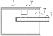
FIG. 1 is a schematic structural diagram of an industrial sewage treatment tank according to an embodiment of the present invention;
FIG. 2 is a schematic structural diagram of a three-phase separator according to an embodiment of the present invention;
fig. 3 is a top view of the buffer pool according to the embodiment of the present invention.
Description of reference numerals:
10. an anaerobic tank; 11. a reactor; 12. a low speed impeller; 13. a mud collecting pit; 14. a sludge return port; 20. a buffer pool; 21. a sloped wall; 22. a three-phase separator; 221. a reflective plate; 222. an air chamber; 223. a water collection platform; 23. a circulation pipe; 24. a circulation pump; 25. a water collection tank; 26. a first air duct; 27. an overflow port; 30. a water distributor; 31. a water distribution pipe; 40. a sludge pump.
Detailed Description
The embodiments of the present invention will be further explained with reference to the drawings.
Example (b):
as shown in fig. 1, an industrial sewage treatment tank comprises an anaerobic tank 10 and a buffer tank 20 which are combined and adjacently arranged, wherein a conical reactor 11 is arranged at the bottom of the anaerobic tank 10, a sludge collection pit 13 is arranged at the left side of the bottom of the anaerobic tank 10, a low-speed impeller 12 is also arranged in the anaerobic tank 10, the low-speed impeller 12 is arranged at the right side of the bottom of the anaerobic tank 10, the impeller direction is parallel to the right side wall of the anaerobic tank 10, and a water distributor 30 is arranged above the anaerobic tank 10; a three-phase separator 22 is arranged in the buffer tank 20, a gas-phase separation port and a liquid-phase separation port which correspond to the three-phase separator 22 in the buffer tank 20 are respectively provided with a gas-guide tube and a water-collecting tank 25, and the bottom of the buffer tank 20 is provided with a sludge return port 14 communicated with the anaerobic tank 10.
In this embodiment, the water distributor 30 is a siphon pulse water distributor, as shown in fig. 1, the water distributor 31 of the water distributor 30 extends to the bottom of the anaerobic tank 10 and is located right above the reactor 11, the end of the water distributor 31 of the water distributor 30 is in a trumpet shape, the water distributor 30 is simple and convenient to operate and has the functions of hydraulic stirring and water distribution uniformity, the pipe diameter can be determined according to the specific design flow, high efficiency, energy saving, rapid water distribution and convenient maintenance can be realized, the sludge concentration and muddy water mixing effect are ensured by distributing water at the bottom of the anaerobic tank 10, the generation of inflammable and malodorous gases is controlled, so that under a better treatment effect, the retention time is shortened, the tank capacity is reduced, and the investment cost is reduced.
In this embodiment, as shown in fig. 2, the three-phase separator 22 includes a plurality of reflection plates 221 arranged in a zigzag manner, two adjacent reflection plates 221 are connected at a wave crest, an opening is formed at a wave trough, an air chamber 222 is formed between two adjacent reflection plates 221 at the wave crest, and a first air duct 26 communicated with the air chamber 222 is arranged in the buffer tank 20; as shown in fig. 2 and 3, a water collecting platform 223 is arranged above the reflection plate 221, an overflow port is arranged between the side edge of the water collecting platform 223 and the inner wall of the buffer pool 20, a water collecting tank 25 extending to the outside of the buffer pool 20 is arranged at the top of the water collecting platform 223, and the height of the top surface of the water collecting platform 223 gradually decreases from the middle to the periphery, so that sludge particles fall back and are collected conveniently, and sludge loss is reduced.
The sewage to be treated flows into the anaerobic tank 10 from the bottom and is mixed and contacted with the sludge in the sludge layer, the microorganisms in the sludge decompose the organic matters in the sewage and convert the organic matters into methane, the methane is continuously discharged in the form of micro bubbles, the micro bubbles are continuously merged in the ascending process to gradually form larger bubbles, sludge liquid with thinner sludge concentration is formed at the upper part of the sludge bed due to the stirring of the methane, the sludge liquid and water ascend and enter the three-phase separator 22, when the methane touches the reflecting plate 221 at the lower part of the three-phase separator 22, the methane is folded around the reflecting plate 221 and then passes through the water layer to enter the gas chamber 222, the methane concentrated in the gas chamber 222 is guided out by a first conduit, solid and liquid are reflected to enter the settling zone of the three-phase separator 22, namely the zone between the reflecting plate 221 and the water collecting platform 223, the sludge in the sewage is flocculated, the particles are gradually increased and are settled under the action of gravity, and slides back into the anaerobic tank 10 through the sludge return port 14, so that a large amount of sludge is accumulated in the reaction zone of the anaerobic tank 10, and treated effluent separated from the sludge overflows from an overflow port 27 of the settling zone and is discharged through a water collecting tank 25.
The utility model discloses a sewage treatment structure that anaerobism pond 10 and buffer pool 20 combined together, set up low-speed impeller 12 in anaerobism pond 10, sewage in promoting anaerobism pond 10 through low-speed impeller 12 carries out slow flow, form the sinuous flow, can effectively improve the stirring effect in the pond, strengthen reaction efficiency, furthermore, still set up three-phase separator 22 in buffer pool 20, the marsh gas and the water that will separate out are collected respectively, the mud separation that carries the aquatic simultaneously blocks down, flow back to in the anaerobism pond 10 through mud backward flow mouth 14, can reduce the degree that mud runs off in the anaerobism pond 10.
In another embodiment, as shown in fig. 1, a circulation pump 24 is disposed above the water collecting platform 223 in the buffer tank 20, a water outlet of the circulation pump 24 is connected to a circulation pipe 23, a water inlet connected to the circulation pipe 23 is disposed on the water distributor 30, and partial treated water is utilized by adding the circulation pump 24 to dilute the sewage, so as to prevent the sludge from blocking the sludge return port 14 and the low-speed impeller 12.
In another embodiment, as shown in fig. 1, a second air duct is provided in the anaerobic tank 10, and the second air duct and the first air duct 26 converge and extend to the outside of the buffer tank 20.
In another embodiment, as shown in fig. 1, the bottom of the buffer tank 20 is provided with an inclined wall 21 corresponding to the solid phase separation port of the three-phase separator 22, and the inclined wall 21 is inclined toward the sludge return port 14, so that the sludge separated by the three-phase separator 22 can flow back to the anaerobic tank 10.
In another embodiment, as shown in fig. 1, the bottom of the anaerobic tank 10 is provided with a slope of 0.5%, and the slope is towards the sludge collecting pit 13, so that the excess sludge can flow into the sludge collecting pit 13 for treatment.
In another embodiment, as shown in fig. 1, a sludge pipe is arranged in the sludge collection pit 13, one end of the sludge pipe is positioned at the bottom of the sludge collection pit 13, and the other end of the sludge pipe extends out of the anaerobic tank 10 and is connected with a sludge pump 40, so that the sludge in the sludge collection pit 13 can be conveniently discharged, or the sludge collection pit 13 can be conveniently flushed.
The above-mentioned embodiments only express the specific embodiments of the present invention, and the description thereof is specific and detailed, but not construed as limiting the scope of the present invention. It should be noted that, for those skilled in the art, without departing from the spirit of the present invention, several variations and modifications can be made, which are within the scope of the present invention.
Claims (10)
1. The industrial sewage treatment tank is characterized by comprising an anaerobic tank and a buffer tank which are combined and arranged adjacently, wherein a conical reactor is arranged at the bottom of the anaerobic tank, a sludge collecting pit is arranged at one side of the bottom of the anaerobic tank, a low-speed impeller is also arranged in the anaerobic tank, and a water distributor is arranged above the anaerobic tank; the anaerobic tank is characterized in that a three-phase separator is arranged in the buffer tank, a gas-phase separation port and a liquid-phase separation port which correspond to the three-phase separator in the buffer tank are respectively provided with a gas-guide tube and a water-collecting tank, and the bottom of the buffer tank is provided with a sludge return port communicated with the anaerobic tank.
2. The industrial sewage treatment pond according to claim 1, wherein the water distributor is a siphon pulse water distributor, and the water distribution pipe of the water distributor extends to the bottom of the anaerobic pond and is positioned right above the reactor.
3. The industrial wastewater treatment tank of claim 2, wherein the ends of the water distribution pipes of the water distributor are trumpet-shaped.
4. The industrial sewage treatment tank according to claim 1, wherein the three-phase separator comprises a plurality of reflection plates arranged in a zigzag manner, two adjacent reflection plates are connected at a wave crest, an opening is formed at a wave trough, an air chamber is formed between the two adjacent reflection plates at the wave crest, and a first air duct communicated with the air chamber is arranged in the buffer tank; the top of reflecting plate is equipped with water collection platform, be equipped with the overflow mouth between water collection platform's the side and the inner wall of buffer pool, water collection platform's top is equipped with the water catch bowl that extends to the buffer pool outside.
5. The industrial sewage treatment pond according to claim 4, wherein a circulating pump is arranged above the water collecting platform in the buffer pond, a water outlet of the circulating pump is connected with a circulating pipe, and a water inlet connected with the circulating pipe is arranged on the water distributor.
6. The industrial sewage treatment pond according to claim 4, wherein the height of the top surface of the water collection platform is gradually reduced from the middle to the periphery.
7. The industrial sewage treatment pond according to claim 4, wherein a second air duct is arranged in the anaerobic pond, and the second air duct and the first air duct are converged and then extend to the outside of the buffer pond.
8. The industrial sewage treatment tank as claimed in claim 1, wherein the bottom of the buffer tank is provided with an inclined wall corresponding to the solid phase separation port of the three-phase separator, and the inclined wall is inclined towards the sludge return port.
9. The industrial sewage treatment pond according to claim 1, wherein the bottom of the anaerobic pond is provided with a slope of 0.5% and the slope is towards the mud collection pit.
10. The industrial sewage treatment pond according to claim 1, wherein a sludge pipe is arranged in the sludge collection pit, one end of the sludge pipe is positioned at the bottom of the sludge collection pit, and the other end of the sludge pipe extends out of the anaerobic pond and is connected with a sludge pump.
Priority Applications (1)
| Application Number | Priority Date | Filing Date | Title |
|---|---|---|---|
| CN202220858106.5U CN217398700U (en) | 2022-04-14 | 2022-04-14 | Industrial sewage treatment pond |
Applications Claiming Priority (1)
| Application Number | Priority Date | Filing Date | Title |
|---|---|---|---|
| CN202220858106.5U CN217398700U (en) | 2022-04-14 | 2022-04-14 | Industrial sewage treatment pond |
Publications (1)
| Publication Number | Publication Date |
|---|---|
| CN217398700U true CN217398700U (en) | 2022-09-09 |
Family
ID=83140794
Family Applications (1)
| Application Number | Title | Priority Date | Filing Date |
|---|---|---|---|
| CN202220858106.5U Active CN217398700U (en) | 2022-04-14 | 2022-04-14 | Industrial sewage treatment pond |
Country Status (1)
| Country | Link |
|---|---|
| CN (1) | CN217398700U (en) |
-
2022
- 2022-04-14 CN CN202220858106.5U patent/CN217398700U/en active Active
Similar Documents
| Publication | Publication Date | Title |
|---|---|---|
| CN102659227B (en) | Middle-set type high density sediment water purification tank and purification technology thereof | |
| KR100398774B1 (en) | Method and device for anaerobic purification of waste water using the UASB method | |
| CN103011404B (en) | Internal-mixing anaerobic reaction tank | |
| CN209522646U (en) | A kind of bio-contact oxidation High-rate sedimentation integration facility | |
| CN103011402A (en) | Double-circulation anaerobic reactor | |
| CN102491511B (en) | Efficient anaerobic bioreactor | |
| CN109231454A (en) | A kind of deflector type domestic sewage processing system and application | |
| CN201132800Y (en) | Highly effective mixing upwash reactor for anaerobic solid | |
| CN203007035U (en) | Dual-circulation anaerobic reactor | |
| CN219907230U (en) | IC anaerobic reactor for high concentration waste water treatment | |
| CN202625908U (en) | Central-positioned high-density precipitating water purifying pond | |
| CN217398700U (en) | Industrial sewage treatment pond | |
| CN218262148U (en) | Anaerobic reactor | |
| CN215559287U (en) | Three-phase separation device applied to efficient anaerobic reactor | |
| CN207418381U (en) | A kind of Aerobic three-phase separator | |
| CN203007037U (en) | Internal mixing anaerobic reactor | |
| CN202337712U (en) | Efficient anaerobic bioreactor | |
| CN202499757U (en) | Novel high-concentration wastewater anaerobic fermentation device | |
| CN105152324A (en) | Anaerobic ammonia oxidation reactor capable of classifying sludge through cyclone | |
| CN114956447A (en) | Industrial sewage treatment pond | |
| CN205687912U (en) | A kind of from air supporting efficient anaerobe reactor | |
| CN201634671U (en) | Four-phase separator of anaerobic fermentation apparatus | |
| CN204939083U (en) | A kind of eddy flow sludge classification anaerobic ammonia oxidation reactor | |
| CN114275890A (en) | High-efficiency skid-mounted three-phase separator in high-load anaerobic system | |
| CN202499758U (en) | Efficient precipitation/return anaerobic fermentation reactor |
Legal Events
| Date | Code | Title | Description |
|---|---|---|---|
| GR01 | Patent grant | ||
| GR01 | Patent grant |