CN217393907U - Cutting device for preventing color steel plate from deforming - Google Patents
Cutting device for preventing color steel plate from deforming Download PDFInfo
- Publication number
- CN217393907U CN217393907U CN202221598647.5U CN202221598647U CN217393907U CN 217393907 U CN217393907 U CN 217393907U CN 202221598647 U CN202221598647 U CN 202221598647U CN 217393907 U CN217393907 U CN 217393907U
- Authority
- CN
- China
- Prior art keywords
- sets
- groups
- color steel
- base
- cutting
- Prior art date
- Legal status (The legal status is an assumption and is not a legal conclusion. Google has not performed a legal analysis and makes no representation as to the accuracy of the status listed.)
- Active
Links
Images


Classifications
-
- Y—GENERAL TAGGING OF NEW TECHNOLOGICAL DEVELOPMENTS; GENERAL TAGGING OF CROSS-SECTIONAL TECHNOLOGIES SPANNING OVER SEVERAL SECTIONS OF THE IPC; TECHNICAL SUBJECTS COVERED BY FORMER USPC CROSS-REFERENCE ART COLLECTIONS [XRACs] AND DIGESTS
- Y02—TECHNOLOGIES OR APPLICATIONS FOR MITIGATION OR ADAPTATION AGAINST CLIMATE CHANGE
- Y02P—CLIMATE CHANGE MITIGATION TECHNOLOGIES IN THE PRODUCTION OR PROCESSING OF GOODS
- Y02P70/00—Climate change mitigation technologies in the production process for final industrial or consumer products
- Y02P70/10—Greenhouse gas [GHG] capture, material saving, heat recovery or other energy efficient measures, e.g. motor control, characterised by manufacturing processes, e.g. for rolling metal or metal working
Landscapes
- Accessories And Tools For Shearing Machines (AREA)
Abstract
The utility model relates to the technical field of cutting devices, in particular to a cutting device for preventing color steel plates from deforming, which improves the convenience of fixing the positions of the color steel plates and reduces the deformation of the color steel plates in the cutting process by pressing and shaping the color steel plates; the on-line screen storage device comprises a base, conveyor, cutting mechanism, two sets of bed dies, the multiunit guide post, the roof, a supporting plate, first pneumatic cylinder, the multiunit support column, two sets of mould and multiunit spring of going up, the base top is provided with conveyor, be provided with cutting mechanism in the base, cutting mechanism is used for cutting various steel sheet, two sets of bed dies are all installed on the base top, and be provided with the clearance between two sets of bed dies, the multiunit guide post bottom all is connected with the base top, the roof bottom is connected with multiunit guide post top, slip suit is on the multiunit guide post lateral wall about the backup pad, the stiff end of first pneumatic cylinder is installed on the roof top, the removal end and the backup pad top of first pneumatic cylinder are connected.
Description
Technical Field
The utility model relates to a cutting device's technical field especially relates to a prevent cutting device of various steel sheet deformation.
Background
The color steel is a color coated steel plate which is a steel plate with an organic coating and has the characteristics of good corrosion resistance, bright color, beautiful appearance, convenient processing and forming, original strength of the steel plate, lower cost and the like, since the color steel plate is generally designed to be polygonal, in the current prior art CN202021161028.0, the equipment control module respectively controls the working states of the first motor and the second motor, the conveying roller is driven by the first motor, the plate material which is matched with the rotating roller and is oppositely arranged on the conveying platform is conveyed to the position right below the fixed plate, the second motor drives the cam to rotate, the cam drives the connecting rod to drive the cutter to move downwards until the cutter cuts the plate material, the structure is simple and practical, but the device is inconvenient for shaping the color steel plate, so that the color steel plate is easy to deform in the cutting process, therefore, the cutting device is convenient for shaping the color steel plate and reducing the cutting deformation of the color steel plate.
SUMMERY OF THE UTILITY MODEL
In order to solve the technical problem, the utility model provides an improve the rigidity convenience of various steel sheet, through pressing the design with various steel sheet to reduce the cutting device that prevents various steel sheet deformation of the condition of deformation in the various steel sheet cutting process.
The utility model discloses a cutting device for preventing color steel plate deformation, which comprises a base, a conveying device, a cutting mechanism, two groups of lower dies, a plurality of groups of guide posts, a top plate, a supporting plate, a first hydraulic cylinder, a plurality of groups of support posts, two groups of upper dies and a plurality of groups of springs, wherein the top end of the base is provided with the conveying device, the base is internally provided with the cutting mechanism, the cutting mechanism is used for cutting color steel plates, the two groups of lower dies are both arranged at the top end of the base, a gap is arranged between the two groups of lower dies, the bottom ends of the plurality of groups of guide posts are both connected with the top end of the base, the bottom end of the top plate is connected with the top ends of the plurality of groups of guide posts, the supporting plate is sleeved on the outer side wall of the plurality of groups of guide posts in a sliding manner up and down, the fixed end of the first hydraulic cylinder is arranged at the top end of the top plate, the plurality of groups of support posts are respectively provided with a limiting plate, the top ends of the two groups of upper dies are respectively connected with the bottom ends of the plurality of groups of supporting columns, the two groups of upper dies are respectively arranged corresponding to the two groups of lower dies in position, and the plurality of groups of springs are respectively matched and sleeved on the outer side walls of the plurality of groups of supporting columns; at first carry various steel sheet through conveyor from a left side to the right side, make various steel sheet remove to two sets of bed die tops, later remove the end through first pneumatic cylinder and promote the backup pad and slide down, make the backup pad drive two sets of mould downstream on through the multiunit support column, thereby make two sets of mould downstream on back and two sets of bed die cooperation press the design with various steel sheet, later through cutting mechanism to various steel sheet cutting process, provide decurrent motive force to two sets of bed dies through setting up the multiunit spring, improve two sets of elasticity of pressing of mould to various steel sheet on, improve the rigidity convenience of various steel sheet, through pressing the design with various steel sheet, thereby reduce the circumstances of deformation in the various steel sheet cutting process.
Preferably, the cutting mechanism comprises a first shell, a first slider, a plurality of groups of second hydraulic cylinders, a second shell, a circular saw blade, a screw rod and a first motor, the first shell is arranged at the bottom of the inner side wall of the base, the first slider is arranged on the first shell in a front-back sliding manner, the fixed ends of the plurality of groups of second hydraulic cylinders are all arranged at the top end of the first slider, the moving ends of the plurality of groups of second hydraulic cylinders are all connected with the bottom end of the second shell, a driving motor is arranged in the second shell, the circular saw blade is rotatably arranged on the outer side wall of the second shell through a rotating shaft, a through groove is arranged at the top end of the base and is positioned between the two groups of lower dies, the upper part of the circular saw blade extends into the through groove, the driving motor drives the circular saw blade to rotate, the front end and the back end of the screw rod are respectively rotatably arranged on the inner side wall of the first shell through bearings, and the first slider is matched and screwed on the outer side wall of the screw rod, the first motor is arranged at the front end of the first shell, and the output end of the first motor is concentrically connected with the front end of the screw rod; remove the end through control multiunit second pneumatic cylinder and promote the second casing rebound, make the second casing drive circular saw blade rebound, the circular saw blade top passes the logical groove and the contact of various steel sheet bottom of base, later driving motor drives circular saw blade rotatory, make circular saw blade rotatory back with the cutting of various steel sheet, it is rotatory through opening first motor drive lead screw, it is forward or backward to drive first slider after the lead screw is rotatory, make first slider drive the circular saw blade back-and-forth movement through multiunit second pneumatic cylinder, and then make circular saw blade to the whole cutting of various steel sheet, improve the convenience of cutting device to the cutting of various steel sheet.
Preferably, the conveying device comprises a gantry support, a transmission roller, two groups of second sliding blocks and a conveying roller, the bottom end of the gantry support is connected with the top end of the base, the front end and the rear end of the transmission roller are respectively rotatably mounted on the inner side wall of the gantry support, sliding grooves are respectively formed in the front side and the rear side of the gantry support, the two groups of second sliding blocks are respectively arranged on the sliding grooves in the two sides of the gantry support in a vertically sliding manner, the front end and the rear end of the conveying roller are respectively rotatably mounted on the outer side walls of the two groups of second sliding blocks, and grooves matched with the color steel plates are formed in the outer side walls of the transmission roller and the conveying roller; at first place the driving roller top with various steel sheet, through with two sets of second sliders downstream, make two sets of second sliders drive the conveying roller downstream to make driving roller and conveying roller with various steel sheet centre gripping, later through rotatory with the driving roller, make rotatory back of driving roller and conveying roller cooperation carry various steel sheet right, improve the operation convenience of various steel sheet automatic conveying cutting, improve the cutting efficiency of device to various steel sheet.
Preferably, the gantry crane further comprises two groups of fixing pieces and two groups of third hydraulic cylinders, wherein the two groups of fixing pieces are respectively arranged on the outer side walls of the front side and the rear side of the gantry support, the fixed ends of the two groups of third hydraulic cylinders are respectively arranged at the top ends of the two groups of fixing pieces, and the moving ends of the two groups of third hydraulic cylinders are respectively connected with the top ends of the two groups of second sliding blocks; through controlling the flexible length of two sets of third pneumatic cylinders removal end, make two sets of third pneumatic cylinders drive two sets of second sliders synchronous lifting movement to make two sets of second sliders drive the conveying roller and reciprocate, improve the convenience that the device carried various steel sheet.
Preferably, the automatic feeding device also comprises a reduction gearbox and a second motor, wherein the reduction gearbox is arranged on the front side wall of the gantry support, the output end of the reduction gearbox is concentrically connected with the front end of the transmission roller, the second motor is arranged on the outer side of the reduction gearbox, and the output end of the second motor is connected with the input end of the reduction gearbox; the second motor is started to drive the transmission roller to rotate through the reduction gearbox, so that the convenience of automatic conveying of the device in the cutting process of the color steel plate is improved, and the labor intensity of manual conveying is reduced.
Preferably, the device also comprises a plurality of groups of limiting rods, wherein the plurality of groups of limiting rods are respectively arranged at the top ends of the two groups of upper dies; through setting up the multiunit gag lever post, at first promote the mould downstream through two sets of springs after the backup pad downstream, the backup pad continues downstream after two sets of last mould bottoms and various steel sheet contact, later makes multiunit gag lever post top and backup pad bottom contact to multiunit gag lever post is fixed spacingly to two sets of last moulds, improves the stability of pressing down of two sets of last moulds to various steel sheet.
Preferably, the two groups of lower dies and the two groups of upper dies are respectively provided with a groove matched with the color steel plate; through being provided with the recess that matches with various steel sheet on will two sets of bed dies and two sets of upper dies respectively, improve the bed die and go up the mould to the design effect of various steel sheet, reduce the deformation condition of various steel sheet cutting.
Compared with the prior art, the beneficial effects of the utility model are that: at first carry various steel sheet through conveyor from a left side to the right side, make various steel sheet remove to two sets of bed die tops, later remove the end through first pneumatic cylinder and promote the backup pad and slide down, make the backup pad drive two sets of mould downstream on through the multiunit support column, thereby make two sets of mould downstream on back and two sets of bed die cooperation press the design with various steel sheet, later through cutting mechanism to various steel sheet cutting process, provide decurrent motive force to two sets of bed dies through setting up the multiunit spring, improve two sets of elasticity of pressing of mould to various steel sheet on, improve the rigidity convenience of various steel sheet, through pressing the design with various steel sheet, thereby reduce the circumstances of deformation in the various steel sheet cutting process.
Drawings
Fig. 1 is a schematic structural diagram of the present invention;
FIG. 2 is a partial schematic view showing the connection of a guide post to a top plate or the like;
FIG. 3 is a side view of the first housing in partial structural view, connected to a lead screw or the like;
FIG. 4 is a side view of a part of the structure of the second slider connected to a feed roller;
FIG. 5 is a schematic view of a partial axial structure of a support column connected to a limiting plate;
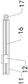
in the drawings, the reference numbers: 1. a base; 2. a lower die; 3. a guide post; 4. a top plate; 5. a support plate; 6. a first hydraulic cylinder; 7. a support pillar; 8. a limiting plate; 9. an upper die; 10. a spring; 11. a first housing; 12. a first slider; 13. a second hydraulic cylinder; 14. a second housing; 15. a circular saw blade; 16. a lead screw; 17. a first motor; 18. a gantry support; 19. a driving roller; 20. a second slider; 21. a conveying roller; 22. a fixing member; 23. a third hydraulic cylinder; 24. a reduction gearbox; 25. a second motor; 26. a limiting rod.
Detailed Description
In order to facilitate understanding of the present invention, the present invention will be described more fully hereinafter with reference to the accompanying drawings. The invention may be embodied in many different forms and is not limited to the embodiments described herein. Rather, these embodiments are provided so that this disclosure will be thorough and complete.
Two groups of lower dies 2 are all arranged at the top end of a base 1, a gap is arranged between the two groups of lower dies 2, the bottom ends of a plurality of groups of guide posts 3 are all connected with the top end of the base 1, the bottom end of a top plate 4 is connected with the top ends of a plurality of groups of guide posts 3, a support plate 5 is sleeved on the outer side walls of the plurality of groups of guide posts 3 in an up-and-down sliding manner, the fixed end of a first hydraulic cylinder 6 is arranged at the top end of the top plate 4, the moving end of the first hydraulic cylinder 6 is connected with the top end of the support plate 5, a plurality of groups of support posts 7 are all arranged on the support plate 5 in an up-and-down sliding manner, the top ends of a plurality of groups of support posts 7 are respectively provided with a limiting plate 8, the top ends of two groups of upper dies 9 are respectively connected with the bottom ends of a plurality of groups of support posts 7, two groups of upper dies 9 are respectively arranged corresponding to the positions of the two groups of lower dies 2, a plurality of groups of springs 10 are respectively sleeved on the outer side walls of the plurality of groups of support posts 7 in a matching manner, a first shell 11 is arranged at the bottom of the inner side wall of the base 1, a first sliding block 12 in a front and back sliding manner, the fixed ends of a plurality of groups of second hydraulic cylinders 13 are all arranged at the top end of a first sliding block 12, the moving ends of the plurality of groups of second hydraulic cylinders 13 are all connected with the bottom end of a second shell 14, a driving motor is arranged in the second shell 14, a circular saw blade 15 is rotationally arranged on the outer side wall of the second shell 14 through a rotating shaft, a through groove is arranged at the top end of a base 1 and is positioned between two groups of lower dies 2, the upper part of the circular saw blade 15 extends into the through groove, the driving motor drives the circular saw blade 15 to rotate, the front end and the rear end of a screw 16 are respectively rotationally arranged on the inner side wall of a first shell 11 through bearings, the first sliding block 12 is matched with and screwed on the outer side wall of the screw 16, a first motor 17 is arranged at the front end of the first shell 11, the output end of the first motor 17 is concentrically connected with the front end of the screw 16, the bottom end of a gantry support 18 is connected with the top end of the base 1, the front end and the rear end of a driving roller 19 are respectively rotationally arranged on the inner side wall of the gantry support 18, the front side and the rear side of the gantry support 18 are respectively provided with a sliding groove, two groups of second sliding blocks 20 are respectively arranged on the sliding grooves on the two sides of the gantry support 18 in a vertical sliding manner, the front end and the rear end of a conveying roller 21 are respectively rotatably arranged on the outer side walls of the two groups of second sliding blocks 20, grooves matched with color steel plates are arranged on the outer side walls of a transmission roller 19 and the conveying roller 21, two groups of fixing parts 22 are respectively arranged on the outer side walls on the front side and the rear side of the gantry support 18, the fixed ends of two groups of third hydraulic cylinders 23 are respectively arranged on the top ends of the two groups of fixing parts 22, the moving ends of the two groups of third hydraulic cylinders 23 are respectively connected with the top ends of the two groups of second sliding blocks 20, a reduction box 24 is arranged on the front side wall of the gantry support 18, the output end of the reduction box 24 is concentrically connected with the front end of the transmission roller 19, a second motor 25 is arranged on the outer side of the reduction box 24, the output end of the second motor 25 is connected with the input end of the reduction box 24, a plurality of limiting rods 26 are respectively arranged on the top ends of the two groups of upper dies 9, grooves matched with the color steel plates are respectively arranged on the two groups of lower dies 2 and the two groups of upper dies 9; at first carry various steel sheet through conveyor from the left hand right side, make various steel sheet remove to 2 tops of two sets of bed dies, later remove the end through first pneumatic cylinder 6 and promote backup pad 5 lapse, make backup pad 5 drive two sets of mould 9 lapse on through multiunit support column 7, thereby make two sets of moulds 9 lapse after moving down with the cooperation of two sets of bed dies 2 with various steel sheet press down the design, later through cutting mechanism to various steel sheet cutting process, provide decurrent driving force to two sets of bed dies 9 through setting up multiunit spring 10, improve the elasticity of pressing down of two sets of bed dies 9 to various steel sheet, improve the rigidity convenience of various steel sheet, through pressing down the design with various steel sheet, thereby reduce the condition of deformation in the various steel sheet cutting process.
As shown in fig. 1 to 5, the utility model discloses a prevent cutting device of various steel sheet deformation, it is at the during operation, at first place the 19 tops of driving roller with various steel sheet, through with two sets of second sliders 20 downstream, make two sets of second sliders 20 drive conveying roller 21 downstream, thereby make driving roller 19 and conveying roller 21 with various steel sheet centre gripping, later through rotatory with driving roller 19, make behind the driving roller 19 rotatory with the conveying roller 21 cooperation with the various steel sheet carry right, later various steel sheet removes to 2 tops of two sets of bed dies, remove the end through first pneumatic cylinder 6 and promote backup pad 5 and slide down, make backup pad 5 drive two sets of top dies 9 downstream through multiunit support column 7, thereby make behind the two sets of top dies 9 downstream with the cooperation of 2 of two sets of bed dies press down the various steel sheet and stereotype, then through circular saw blade 15 to the whole cutting of various steel sheet.
The utility model discloses the main function who realizes does: at first carry various steel sheet through conveyor from the left hand right side, make various steel sheet remove to 2 tops of two sets of bed dies, later remove the end through first pneumatic cylinder 6 and promote backup pad 5 lapse, make backup pad 5 drive two sets of mould 9 lapse on through multiunit support column 7, thereby make two sets of moulds 9 lapse after moving down with the cooperation of two sets of bed dies 2 with various steel sheet press down the design, later through cutting mechanism to various steel sheet cutting process, provide decurrent driving force to two sets of bed dies 9 through setting up multiunit spring 10, improve the elasticity of pressing down of two sets of bed dies 9 to various steel sheet, improve the rigidity convenience of various steel sheet, through pressing down the design with various steel sheet, thereby reduce the condition of deformation in the various steel sheet cutting process.
The cutting device for preventing the color steel plate from deforming of the utility model has the advantages that the installation mode, the connection mode or the setting mode are common mechanical modes, and the cutting device can be implemented as long as the beneficial effects can be achieved; the utility model discloses a prevent cutting device's of various steel sheet deformation bed die 2, first pneumatic cylinder 6, go up mould 9, second pneumatic cylinder 13, circular saw blade 15, first motor 17, third pneumatic cylinder 23, reducing gear box 24 and second motor 25 for purchase on the market, this industry technical staff only need according to its subsidiary operating specification install and operate can, and need not the technical staff in the field and pay creative work.
All technical and scientific terms used herein have the same meaning as commonly understood by one of ordinary skill in the art to which this invention belongs. The terminology used in the description of the invention herein is for the purpose of describing particular embodiments only and is not intended to be limiting of the invention. As used herein, the term "and/or" includes any and all combinations of one or more of the associated listed items.
The foregoing is only a preferred embodiment of the present invention, and it should be noted that, for those skilled in the art, a plurality of modifications and variations can be made without departing from the technical principle of the present invention, and these modifications and variations should also be regarded as the protection scope of the present invention.
Claims (7)
1. A cutting device for preventing color steel plates from deforming is characterized by comprising a base (1), a conveying device, a cutting mechanism, two groups of lower dies (2), a plurality of groups of guide posts (3), a top plate (4), a supporting plate (5), a first hydraulic cylinder (6), a plurality of groups of supporting posts (7), two groups of upper dies (9) and a plurality of groups of springs (10), wherein the conveying device is arranged at the top end of the base (1), the cutting mechanism is arranged in the base (1) and used for cutting color steel plates, the two groups of lower dies (2) are both arranged at the top end of the base (1), a gap is arranged between the two groups of lower dies (2), the bottom ends of the plurality of groups of guide posts (3) are both connected with the top end of the base (1), the bottom end of the top plate (4) is connected with the top ends of the plurality of groups of guide posts (3), the supporting plate (5) is vertically sleeved on the outer side walls of the plurality of the groups of the guide posts (3) in a sliding manner, the fixed end of the first hydraulic cylinder (6) is arranged at the top end of the top plate (4), the removal end and the backup pad (5) top of first pneumatic cylinder (6) are connected, and multiunit support column (7) all slide from top to bottom and set up on backup pad (5), and multiunit support column (7) top is provided with limiting plate (8) respectively, and two sets of top mould (9) tops are connected with multiunit support column (7) bottom respectively to two sets of top mould (9) correspond the setting with two sets of bed die (2) positions respectively, and multiunit spring (10) cooperate the suit respectively on multiunit support column (7) lateral wall.
2. The cutting device for preventing the color steel plate from deforming as claimed in claim 1, wherein the cutting mechanism comprises a first housing (11), a first slider (12), a plurality of sets of second hydraulic cylinders (13), a second housing (14), a circular saw blade (15), a lead screw (16) and a first motor (17), the first housing (11) is installed at the bottom of the inner side wall of the base (1), the first slider (12) is slidably installed on the first housing (11) back and forth, the fixed ends of the plurality of sets of second hydraulic cylinders (13) are installed at the top end of the first slider (12), the moving ends of the plurality of sets of second hydraulic cylinders (13) are connected with the bottom end of the second housing (14), a driving motor is installed in the second housing (14), the circular saw blade (15) is rotatably installed on the outer side wall of the second housing (14) through a rotating shaft, and a through slot is formed at the top end of the base (1), the through slot is located between the two sets of lower molds (2), circular saw blade (15) upper portion stretches into logical inslot portion, and driving motor drives circular saw blade (15) rotation, and both ends are installed on first casing (11) inside wall through the bearing rotation respectively around lead screw (16), and first slider (12) cooperation spiral shell dress is on lead screw (16) lateral wall, and first motor (17) are installed at first casing (11) front end, and first motor (17) output and lead screw (16) front end are connected with one heart.
3. The cutting device for preventing the color steel plate from deforming as claimed in claim 1, wherein the conveying device comprises a gantry support (18), a transmission roller (19), two sets of second sliding blocks (20) and conveying rollers (21), the bottom end of the gantry support (18) is connected with the top end of the base (1), the front end and the rear end of the transmission roller (19) are respectively rotatably mounted on the inner side wall of the gantry support (18), the front side and the rear side of the gantry support (18) are respectively provided with a sliding groove, the two sets of second sliding blocks (20) are respectively slidably arranged on the sliding grooves on the two sides of the gantry support (18) up and down, the front end and the rear end of the conveying rollers (21) are respectively rotatably mounted on the outer side walls of the two sets of second sliding blocks (20), and grooves matched with the color steel plate are formed in the outer side walls of the transmission roller (19) and the conveying rollers (21).
4. The cutting device for preventing the color steel plate from being deformed according to claim 3, further comprising two sets of fixing members (22) and two sets of third hydraulic cylinders (23), wherein the two sets of fixing members (22) are respectively installed on the outer side walls of the front and rear sides of the gantry support (18), the fixed ends of the two sets of third hydraulic cylinders (23) are respectively installed at the top ends of the two sets of fixing members (22), and the moving ends of the two sets of third hydraulic cylinders (23) are respectively connected with the top ends of the two sets of second sliding blocks (20).
5. The cutting device for preventing the color steel plate from deforming as claimed in claim 3, further comprising a reduction gearbox (24) and a second motor (25), wherein the reduction gearbox (24) is installed on the front side wall of the gantry support (18), the output end of the reduction gearbox (24) is concentrically connected with the front end of the driving roller (19), the second motor (25) is installed on the outer side of the reduction gearbox (24), and the output end of the second motor (25) is connected with the input end of the reduction gearbox (24).
6. The cutting device for preventing the color steel plate from deforming as claimed in claim 1, further comprising a plurality of sets of limiting rods (26), wherein the plurality of sets of limiting rods (26) are respectively installed at the top ends of the two sets of upper dies (9).
7. The cutting device for preventing the color steel plate from deforming as claimed in claim 1, wherein the two sets of lower dies (2) and the two sets of upper dies (9) are respectively provided with a groove matched with the color steel plate.
Priority Applications (1)
| Application Number | Priority Date | Filing Date | Title |
|---|---|---|---|
| CN202221598647.5U CN217393907U (en) | 2022-06-25 | 2022-06-25 | Cutting device for preventing color steel plate from deforming |
Applications Claiming Priority (1)
| Application Number | Priority Date | Filing Date | Title |
|---|---|---|---|
| CN202221598647.5U CN217393907U (en) | 2022-06-25 | 2022-06-25 | Cutting device for preventing color steel plate from deforming |
Publications (1)
| Publication Number | Publication Date |
|---|---|
| CN217393907U true CN217393907U (en) | 2022-09-09 |
Family
ID=83147377
Family Applications (1)
| Application Number | Title | Priority Date | Filing Date |
|---|---|---|---|
| CN202221598647.5U Active CN217393907U (en) | 2022-06-25 | 2022-06-25 | Cutting device for preventing color steel plate from deforming |
Country Status (1)
| Country | Link |
|---|---|
| CN (1) | CN217393907U (en) |
Cited By (1)
| Publication number | Priority date | Publication date | Assignee | Title |
|---|---|---|---|---|
| CN116174791A (en) * | 2023-02-14 | 2023-05-30 | 浙江创格科技股份有限公司 | Two-step safety plate shearing machine |
-
2022
- 2022-06-25 CN CN202221598647.5U patent/CN217393907U/en active Active
Cited By (2)
| Publication number | Priority date | Publication date | Assignee | Title |
|---|---|---|---|---|
| CN116174791A (en) * | 2023-02-14 | 2023-05-30 | 浙江创格科技股份有限公司 | Two-step safety plate shearing machine |
| CN116174791B (en) * | 2023-02-14 | 2024-10-11 | 浙江创格科技股份有限公司 | Two-step safety plate shearing machine |
Similar Documents
| Publication | Publication Date | Title |
|---|---|---|
| CN102294843B (en) | Full-automatic bubble pressing machine for blank gift box | |
| CN110524255B (en) | Clock hairpin line ball processingequipment | |
| CN111872266B (en) | Arc-shaped fixing hoop punch forming device | |
| CN102069383A (en) | Shaping system for integrally cutting, crimping and pressing edge | |
| CN217393907U (en) | Cutting device for preventing color steel plate from deforming | |
| CN114618934B (en) | Synchronous push formula stamping device | |
| CN201565775U (en) | Integrated shaping machine for cutting edges, curling edges and pressing edges | |
| CN101664783A (en) | Barrel cover reshaping system of steel barrel | |
| CN219560992U (en) | Bending assembly with quick-change model | |
| CN112496102A (en) | Automatic change bilateral bender | |
| CN201333723Y (en) | Rolling type punching machine | |
| CN217395356U (en) | Cutting equipment is used in drain pipe production and processing | |
| CN215879348U (en) | Supporting platform device of formula five metals bender moves down | |
| CN213288390U (en) | Numerical control bidirectional bending machine | |
| CN215236953U (en) | Supporting platform device of up-moving type five metals bender | |
| CN214516966U (en) | Bending machine for machining sorting machine accessories | |
| CN115431143A (en) | Anti-fatigue polishing device for metal material | |
| CN211161529U (en) | Automobile sheet metal part die | |
| CN114346041A (en) | Stamping device and stamping method for plate processing | |
| CN2316116Y (en) | Multi-station asynchronous block press | |
| CN202242080U (en) | Machine for full-automatically removing bubbles of gift blank box | |
| CN216679689U (en) | Numerical control pipe bending machine for machining automobile parts | |
| CN219520099U (en) | Bending machine capable of preventing excessive bending | |
| CN221388295U (en) | Twisting mechanism of automobile connecting piece | |
| CN214976965U (en) | Small-size punching machine of efficient |
Legal Events
| Date | Code | Title | Description |
|---|---|---|---|
| GR01 | Patent grant | ||
| GR01 | Patent grant | ||
| CB03 | Change of inventor or designer information |
Inventor after: Cong Dejian Inventor after: Wang Liusha Inventor after: Yang Wei Inventor after: Wu Pengfei Inventor before: Cong Dejian Inventor before: Wang Liusha Inventor before: Yang Wei Inventor before: Wu Pengfei |
|
| CB03 | Change of inventor or designer information |